EP0369540B1 - Barreau magnétique pour racle cylindrique dans une machine à imprimer rotative au pochoir - Google Patents
Barreau magnétique pour racle cylindrique dans une machine à imprimer rotative au pochoir Download PDFInfo
- Publication number
- EP0369540B1 EP0369540B1 EP89202871A EP89202871A EP0369540B1 EP 0369540 B1 EP0369540 B1 EP 0369540B1 EP 89202871 A EP89202871 A EP 89202871A EP 89202871 A EP89202871 A EP 89202871A EP 0369540 B1 EP0369540 B1 EP 0369540B1
- Authority
- EP
- European Patent Office
- Prior art keywords
- magnetic bar
- permanent magnets
- bottom part
- elements
- roller squeegee
- Prior art date
- Legal status (The legal status is an assumption and is not a legal conclusion. Google has not performed a legal analysis and makes no representation as to the accuracy of the status listed.)
- Expired - Lifetime
Links
- 238000010022 rotary screen printing Methods 0.000 title claims abstract description 6
- 239000004020 conductor Substances 0.000 claims abstract description 8
- XEEYBQQBJWHFJM-UHFFFAOYSA-N Iron Chemical compound [Fe] XEEYBQQBJWHFJM-UHFFFAOYSA-N 0.000 description 6
- 229910052742 iron Inorganic materials 0.000 description 3
- 239000004809 Teflon Substances 0.000 description 2
- 229920006362 Teflon® Polymers 0.000 description 2
- 238000006073 displacement reaction Methods 0.000 description 2
- 239000004744 fabric Substances 0.000 description 2
- -1 for example Substances 0.000 description 2
- ZOXJGFHDIHLPTG-UHFFFAOYSA-N Boron Chemical compound [B] ZOXJGFHDIHLPTG-UHFFFAOYSA-N 0.000 description 1
- 229910052779 Neodymium Inorganic materials 0.000 description 1
- 229910052772 Samarium Inorganic materials 0.000 description 1
- 239000004411 aluminium Substances 0.000 description 1
- XAGFODPZIPBFFR-UHFFFAOYSA-N aluminium Chemical compound [Al] XAGFODPZIPBFFR-UHFFFAOYSA-N 0.000 description 1
- 229910052782 aluminium Inorganic materials 0.000 description 1
- 229910052796 boron Inorganic materials 0.000 description 1
- 239000010941 cobalt Substances 0.000 description 1
- 229910017052 cobalt Inorganic materials 0.000 description 1
- GUTLYIVDDKVIGB-UHFFFAOYSA-N cobalt atom Chemical compound [Co] GUTLYIVDDKVIGB-UHFFFAOYSA-N 0.000 description 1
- QEFYFXOXNSNQGX-UHFFFAOYSA-N neodymium atom Chemical compound [Nd] QEFYFXOXNSNQGX-UHFFFAOYSA-N 0.000 description 1
- 238000007639 printing Methods 0.000 description 1
- 238000005096 rolling process Methods 0.000 description 1
- KZUNJOHGWZRPMI-UHFFFAOYSA-N samarium atom Chemical compound [Sm] KZUNJOHGWZRPMI-UHFFFAOYSA-N 0.000 description 1
Images

Classifications
-
- B—PERFORMING OPERATIONS; TRANSPORTING
- B41—PRINTING; LINING MACHINES; TYPEWRITERS; STAMPS
- B41F—PRINTING MACHINES OR PRESSES
- B41F15/00—Screen printers
- B41F15/14—Details
- B41F15/40—Inking units
- B41F15/42—Inking units comprising squeegees or doctors
- B41F15/426—Inking units comprising squeegees or doctors the squeegees or doctors being magnetically attracted
Definitions
- the invention relates to a magnetic bar according to the preamble of claim 1.
- the bottom part is according to the invention displaceable in the vertical direction from the top part.
- the bottom part of the magnetic bar can carry out a rotation through 90° about a longitudinal axis thereof.
- GB-A-450 541 describes a magnetic device for holding articles wherein, for releasing said articles, the magnet or magnets can be rotated away from the pole shoes. Also this publication does not envisage or suggest a use in an application in which reduction of the magnetic force of attraction to an intermediate value as desired.
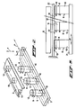
- the magnetic bar 1 comprises a top part 2 and a bottom part 3, the top surface of the top part 2 being provided with a teflon layer 4.
- a printing blanket 5 of the rotary screen printing device bearing a cloth 6 to be printed glides over this teflon layer, a cylindrical stencil 7 containing a roller squeegee 8 rolling over said cloth 6.
- the bottom part 3 of the magnetic bar is provided with a number of cylindrical rods 9 which are disposed next to each other with a space between them in the lengthwise direction of the bar, and which each comprise a bottom part 10 fixed to the part 3 of the magnetic bar, a permanent magnet 11, and a top part 12.
- the permanent magnets 11 are placed in such a way that the polarity of the permanent magnets of the adjacent rods 9 are always alternated. In other words, there is alternately a north pole and a south pole at the top side.
- the permanent magnets can be of the cobalt/samarium type, or of the neodymium/iron/boron type, which are the currently strongest available types of permanent magnets.
- the parts 10 and 12 of each of the cylindrical bars are, like the bottom part 3 of the magnetic bar, preferably made of iron.
- the top part 2 of the magnetic bar is plate-shaped and made of a non-magnetically conducting material such as, for example, aluminium.
- Disc-shaped elements 13, made of a magnetically conducting material such as, for example, iron are disposed herein at regular intervals from each other.
- the elements 13 are circular, with a diameter which corresponds to that of the cylindrical rods 9, and are placed in such a way relative to each other that each element can always be in line with a corresponding rod 9 of the bottom part 3 of the magnetic bar.
- the top surfaces of the elements 13 are flush with the top surface of the plate 2, while the elements 13 at the bottom side of the plate 2 project slightly beyond it, the bottom surfaces of the elements 13 thus being in contact with the top surfaces of the corresponding bars 9 of the bottom part 3 of the magnetic bar.
- the bottom part 3 bearing the permanent magnets can be moved away from the top part in the direction of the double arrow F in Fig. 2, following which said bottom part can be tilted through 90° about a longitudinal axis. If this tilting of the bottom part is carried out without moving this part away from the top part first, the roller squeegee will have a tendency, due to a residual field possibly present, to move sideways at the beginning of the tilting, which can cause damage to the stencil. In general, it is sufficient to move the bottom part approximately 20 mm away from the top part.
- This design of the magnetic bar has the advantage that permanent magnets can now be used while retaining the possibility of exerting a variable force of attraction on the roller squeegee. Through the absence of the coils, a considerable weight saving is obtained, on the one hand, while on the other, no heat is developed in the magnetic bar, something which gives rise to problems such as the buckling of the bar.
- the bottom part of the magnetic bar moves in the lengthwise direction. It is, however, also conceivable for the bottom part to move at right angles to the lengthwise direction of the magnetic bar. In this case the permanent magnets could be placed more closely together.
Landscapes
- Engineering & Computer Science (AREA)
- Mechanical Engineering (AREA)
- Screen Printers (AREA)
Claims (5)
- Barreau magnétique (1) pour un racle à rouleau (8) d'un dispositif rotatif d'impression au pochoir par sérigraphie, ledit barreau portant un certain nombre d'aimants permanents (11) disposés les uns à côté des autres dans la direction longitudinale, afin d'attirer la racle à rouleau (8), caractérisé en ce que- ledit barreau magnétique (1), afin de faire varier la force magnétique d'attraction s'exerçant sur le racle à rouleau (8) comprend deux parties qui peuvent être déplacées l'une par rapport à l'autre, à savoir une partie supérieure fixe (2) et une partie inférieure (3) qui est susceptible de glisser dans la direction longitudinale par rapport à la partie supérieure (2);- les aimants permanents (11) sont disposés dans la partie inférieure (3);- la partie supérieure (2) est une plaque en matériau non-magnétiquement conducteur muni localement d'éléments (13) en matériau magnétiquement conducteur s'étendant au moins sur toute l'épaisseur de la plaque, tandis que la positions des éléments (13) l'un par rapport à l'autre dans ladite plaque correspond à la position relative des aimants permanents (11) dans la partie inférieure du barreau magnétique (1), de telle sorte que les aimants permanents (11) puissent être disposés ensemble en relation de conduction avec des éléments appropriés de la partie supérieure (2); et- la distance entre les éléments (13) de la partie supérieure du barreau magnétique (1) est supérieure au diamètre des aimants permanents (11) de la partie inférieure (3).
- Barreau magnétique selon la revendication 1, caractérisé en la partie inférieure (3) est susceptible d'être déplacée dans la direction verticale en s'éloignant de la partie supérieure (2).
- Barreau magnétique selon la revendication 1 ou 2, caractérisé en ce que la partie inférieure (3) est susceptible de subir une rotation de 90° le long de l'un de ses axes longitudinaux.
- Barreau magnétique selon les revendications précédentes, caractérisé en ce que les aimants permanents (11) présentent une structure de barreaux verticaux (9) en matériau magnétiquement conducteur.
- Barreau magnétique selon les revendications précédentes, caractérisé en ce que les éléments en matériau magnétiquement conducteur sont légèrement en saillie en-dessous de la face inférieure de la plaque.
Priority Applications (1)
| Application Number | Priority Date | Filing Date | Title |
|---|---|---|---|
| AT89202871T ATE103240T1 (de) | 1988-11-14 | 1989-11-10 | Magnetbalken fuer einen rollrakel in einer rotationssiebdruckmaschine. |
Applications Claiming Priority (2)
| Application Number | Priority Date | Filing Date | Title |
|---|---|---|---|
| NL8802794A NL8802794A (nl) | 1988-11-14 | 1988-11-14 | Magneetbalk voor een rolrakel van een rotatiezeefdrukinrichting. |
| NL8802794 | 1988-11-14 |
Publications (2)
| Publication Number | Publication Date |
|---|---|
| EP0369540A1 EP0369540A1 (fr) | 1990-05-23 |
| EP0369540B1 true EP0369540B1 (fr) | 1994-03-23 |
Family
ID=19853217
Family Applications (1)
| Application Number | Title | Priority Date | Filing Date |
|---|---|---|---|
| EP89202871A Expired - Lifetime EP0369540B1 (fr) | 1988-11-14 | 1989-11-10 | Barreau magnétique pour racle cylindrique dans une machine à imprimer rotative au pochoir |
Country Status (4)
| Country | Link |
|---|---|
| EP (1) | EP0369540B1 (fr) |
| AT (1) | ATE103240T1 (fr) |
| DE (1) | DE68914098T2 (fr) |
| NL (1) | NL8802794A (fr) |
Cited By (2)
| Publication number | Priority date | Publication date | Assignee | Title |
|---|---|---|---|---|
| US6227108B1 (en) | 1998-06-12 | 2001-05-08 | Stork Brabank B.V. | Magnet bar |
| CN107244139A (zh) * | 2017-06-21 | 2017-10-13 | 福建浔兴拉链科技股份有限公司 | 一种全自动拉片丝印设备及其使用方法 |
Families Citing this family (4)
| Publication number | Priority date | Publication date | Assignee | Title |
|---|---|---|---|---|
| IT1268551B1 (it) * | 1993-07-06 | 1997-03-04 | Sgm Spa | Dispositivo di contro-partita a magneti permanenti di raclatura particolarmente per macchine da stampa a cilindri rotanti |
| CH689547A5 (de) * | 1995-03-14 | 1999-06-15 | Buser Drucktechnik Ag | Siebdruckanlage. |
| NL1004199C2 (nl) * | 1996-10-04 | 1998-04-07 | Stork Brabant Bv | Magneetbalk voor een rolrakel van een rotatiezeefdrukmachine. |
| FR2775445B1 (fr) * | 1998-03-02 | 2000-04-21 | Braillon Magnetique Sa | Reglette magnetique a aimants permanents pour dispositif d'impression serigraphique |
Citations (2)
| Publication number | Priority date | Publication date | Assignee | Title |
|---|---|---|---|---|
| GB429199A (en) * | 1933-12-12 | 1935-05-27 | Neill James & Co Sheffield Ltd | Improvements in magnetic work holders |
| GB450541A (en) * | 1935-01-15 | 1936-07-15 | Frederick William Windley | Improvements in magnetic chucks, magnetic-separators and magnetic clutches |
Family Cites Families (2)
| Publication number | Priority date | Publication date | Assignee | Title |
|---|---|---|---|---|
| NL71981C (fr) * | 1900-01-01 | |||
| CH426711A (de) * | 1965-07-16 | 1966-12-31 | Aston Martin Co | Siebdruckmaschine mit Rundschablone |
-
1988
- 1988-11-14 NL NL8802794A patent/NL8802794A/nl not_active Application Discontinuation
-
1989
- 1989-11-10 EP EP89202871A patent/EP0369540B1/fr not_active Expired - Lifetime
- 1989-11-10 DE DE68914098T patent/DE68914098T2/de not_active Expired - Fee Related
- 1989-11-10 AT AT89202871T patent/ATE103240T1/de not_active IP Right Cessation
Patent Citations (2)
| Publication number | Priority date | Publication date | Assignee | Title |
|---|---|---|---|---|
| GB429199A (en) * | 1933-12-12 | 1935-05-27 | Neill James & Co Sheffield Ltd | Improvements in magnetic work holders |
| GB450541A (en) * | 1935-01-15 | 1936-07-15 | Frederick William Windley | Improvements in magnetic chucks, magnetic-separators and magnetic clutches |
Non-Patent Citations (1)
| Title |
|---|
| Kunststoff-Lexikon, Carl Hanser Verlag München Wien 1981, page 399, "Polytetrafluorethylen" * |
Cited By (2)
| Publication number | Priority date | Publication date | Assignee | Title |
|---|---|---|---|---|
| US6227108B1 (en) | 1998-06-12 | 2001-05-08 | Stork Brabank B.V. | Magnet bar |
| CN107244139A (zh) * | 2017-06-21 | 2017-10-13 | 福建浔兴拉链科技股份有限公司 | 一种全自动拉片丝印设备及其使用方法 |
Also Published As
| Publication number | Publication date |
|---|---|
| DE68914098D1 (de) | 1994-04-28 |
| DE68914098T2 (de) | 1994-08-04 |
| ATE103240T1 (de) | 1994-04-15 |
| EP0369540A1 (fr) | 1990-05-23 |
| NL8802794A (nl) | 1990-06-01 |
Similar Documents
| Publication | Publication Date | Title |
|---|---|---|
| US9818522B2 (en) | Magnet arrays | |
| US3452310A (en) | Turn-off permanent magnet | |
| US5266914A (en) | Magnetic chuck assembly | |
| EP0369540B1 (fr) | Barreau magnétique pour racle cylindrique dans une machine à imprimer rotative au pochoir | |
| JP6337205B2 (ja) | 磁性体保持装置 | |
| US4542890A (en) | Magnetic chuck | |
| KR960007178A (ko) | 스크린 인쇄 장치 | |
| US3017545A (en) | Device for magnetic clamping | |
| US4014289A (en) | Device for treating a web | |
| US11915864B2 (en) | Magnetic retaining device | |
| EP0633135B1 (fr) | Table magnétique pour machines de sérigraphie rotatives | |
| CN216425780U (zh) | 工件载体和用于工件处理设备的输送系统 | |
| US6837160B2 (en) | Method and apparatus for clamping a printing media | |
| EP1094949B1 (fr) | Dispositif de raclette | |
| US20240058690A1 (en) | Electromagnetic Movement Board | |
| JPS6240741Y2 (fr) | ||
| AU2006294433A1 (en) | Magnet arrays | |
| CH460195A (de) | Magnetbalken | |
| CA3227408A1 (fr) | Appareil magnetique commutable a force de commutation reduite et procedes associes | |
| JPS6254691A (ja) | ロボツトハンド制御方法 | |
| US20230120544A1 (en) | Methods for generating directional magnetic fields and magnetic apparatuses thereof | |
| JPS623250Y2 (fr) | ||
| JP2002103164A (ja) | ワーク切り出し装置 | |
| JPH0912259A (ja) | 吊上装置 | |
| SU1437178A1 (ru) | Магнитна плита |
Legal Events
| Date | Code | Title | Description |
|---|---|---|---|
| PUAI | Public reference made under article 153(3) epc to a published international application that has entered the european phase |
Free format text: ORIGINAL CODE: 0009012 |
|
| AK | Designated contracting states |
Kind code of ref document: A1 Designated state(s): AT DE IT NL |
|
| 17P | Request for examination filed |
Effective date: 19900627 |
|
| 17Q | First examination report despatched |
Effective date: 19920116 |
|
| GRAA | (expected) grant |
Free format text: ORIGINAL CODE: 0009210 |
|
| AK | Designated contracting states |
Kind code of ref document: B1 Designated state(s): AT DE IT NL |
|
| REF | Corresponds to: |
Ref document number: 103240 Country of ref document: AT Date of ref document: 19940415 Kind code of ref document: T |
|
| ITF | It: translation for a ep patent filed | ||
| REF | Corresponds to: |
Ref document number: 68914098 Country of ref document: DE Date of ref document: 19940428 |
|
| PLBE | No opposition filed within time limit |
Free format text: ORIGINAL CODE: 0009261 |
|
| STAA | Information on the status of an ep patent application or granted ep patent |
Free format text: STATUS: NO OPPOSITION FILED WITHIN TIME LIMIT |
|
| 26N | No opposition filed | ||
| PGFP | Annual fee paid to national office [announced via postgrant information from national office to epo] |
Ref country code: AT Payment date: 19981015 Year of fee payment: 10 |
|
| PGFP | Annual fee paid to national office [announced via postgrant information from national office to epo] |
Ref country code: DE Payment date: 19981021 Year of fee payment: 10 |
|
| PGFP | Annual fee paid to national office [announced via postgrant information from national office to epo] |
Ref country code: NL Payment date: 19981130 Year of fee payment: 10 |
|
| PG25 | Lapsed in a contracting state [announced via postgrant information from national office to epo] |
Ref country code: AT Free format text: LAPSE BECAUSE OF NON-PAYMENT OF DUE FEES Effective date: 19991110 |
|
| PG25 | Lapsed in a contracting state [announced via postgrant information from national office to epo] |
Ref country code: NL Free format text: LAPSE BECAUSE OF NON-PAYMENT OF DUE FEES Effective date: 20000601 |
|
| NLV4 | Nl: lapsed or anulled due to non-payment of the annual fee |
Effective date: 20000601 |
|
| PG25 | Lapsed in a contracting state [announced via postgrant information from national office to epo] |
Ref country code: DE Free format text: LAPSE BECAUSE OF NON-PAYMENT OF DUE FEES Effective date: 20000901 |
|
| PG25 | Lapsed in a contracting state [announced via postgrant information from national office to epo] |
Ref country code: IT Free format text: LAPSE BECAUSE OF NON-PAYMENT OF DUE FEES;WARNING: LAPSES OF ITALIAN PATENTS WITH EFFECTIVE DATE BEFORE 2007 MAY HAVE OCCURRED AT ANY TIME BEFORE 2007. THE CORRECT EFFECTIVE DATE MAY BE DIFFERENT FROM THE ONE RECORDED. Effective date: 20051110 |