EP0369618B1 - Moteur pour véhicule - Google Patents
Moteur pour véhicule Download PDFInfo
- Publication number
- EP0369618B1 EP0369618B1 EP89310884A EP89310884A EP0369618B1 EP 0369618 B1 EP0369618 B1 EP 0369618B1 EP 89310884 A EP89310884 A EP 89310884A EP 89310884 A EP89310884 A EP 89310884A EP 0369618 B1 EP0369618 B1 EP 0369618B1
- Authority
- EP
- European Patent Office
- Prior art keywords
- shaft
- crank case
- center axis
- disposed
- main shaft
- Prior art date
- Legal status (The legal status is an assumption and is not a legal conclusion. Google has not performed a legal analysis and makes no representation as to the accuracy of the status listed.)
- Expired - Lifetime
Links
- 230000005540 biological transmission Effects 0.000 claims description 61
- 239000007858 starting material Substances 0.000 claims description 6
- 238000002485 combustion reaction Methods 0.000 claims description 4
- 239000003921 oil Substances 0.000 description 11
- 230000003247 decreasing effect Effects 0.000 description 4
- 239000010687 lubricating oil Substances 0.000 description 3
- 239000002828 fuel tank Substances 0.000 description 2
- XLYOFNOQVPJJNP-UHFFFAOYSA-N water Substances O XLYOFNOQVPJJNP-UHFFFAOYSA-N 0.000 description 2
- 239000000498 cooling water Substances 0.000 description 1
- 230000000694 effects Effects 0.000 description 1
- 238000004519 manufacturing process Methods 0.000 description 1
- 239000002184 metal Substances 0.000 description 1
- 230000003134 recirculating effect Effects 0.000 description 1
- 230000000630 rising effect Effects 0.000 description 1
Images



Classifications
-
- F—MECHANICAL ENGINEERING; LIGHTING; HEATING; WEAPONS; BLASTING
- F02—COMBUSTION ENGINES; HOT-GAS OR COMBUSTION-PRODUCT ENGINE PLANTS
- F02B—INTERNAL-COMBUSTION PISTON ENGINES; COMBUSTION ENGINES IN GENERAL
- F02B61/00—Adaptations of engines for driving vehicles or for driving propellers; Combinations of engines with gearing
- F02B61/02—Adaptations of engines for driving vehicles or for driving propellers; Combinations of engines with gearing for driving cycles
-
- F—MECHANICAL ENGINEERING; LIGHTING; HEATING; WEAPONS; BLASTING
- F02—COMBUSTION ENGINES; HOT-GAS OR COMBUSTION-PRODUCT ENGINE PLANTS
- F02B—INTERNAL-COMBUSTION PISTON ENGINES; COMBUSTION ENGINES IN GENERAL
- F02B75/00—Other engines
- F02B75/16—Engines characterised by number of cylinders, e.g. single-cylinder engines
- F02B75/18—Multi-cylinder engines
- F02B75/20—Multi-cylinder engines with cylinders all in one line
-
- F—MECHANICAL ENGINEERING; LIGHTING; HEATING; WEAPONS; BLASTING
- F02—COMBUSTION ENGINES; HOT-GAS OR COMBUSTION-PRODUCT ENGINE PLANTS
- F02F—CYLINDERS, PISTONS OR CASINGS, FOR COMBUSTION ENGINES; ARRANGEMENTS OF SEALINGS IN COMBUSTION ENGINES
- F02F1/00—Cylinders; Cylinder heads
- F02F1/24—Cylinder heads
- F02F1/42—Shape or arrangement of intake or exhaust channels in cylinder heads
- F02F1/4214—Shape or arrangement of intake or exhaust channels in cylinder heads specially adapted for four or more valves per cylinder
-
- F—MECHANICAL ENGINEERING; LIGHTING; HEATING; WEAPONS; BLASTING
- F02—COMBUSTION ENGINES; HOT-GAS OR COMBUSTION-PRODUCT ENGINE PLANTS
- F02B—INTERNAL-COMBUSTION PISTON ENGINES; COMBUSTION ENGINES IN GENERAL
- F02B75/00—Other engines
- F02B75/02—Engines characterised by their cycles, e.g. six-stroke
- F02B2075/022—Engines characterised by their cycles, e.g. six-stroke having less than six strokes per cycle
- F02B2075/027—Engines characterised by their cycles, e.g. six-stroke having less than six strokes per cycle four
-
- F—MECHANICAL ENGINEERING; LIGHTING; HEATING; WEAPONS; BLASTING
- F02—COMBUSTION ENGINES; HOT-GAS OR COMBUSTION-PRODUCT ENGINE PLANTS
- F02B—INTERNAL-COMBUSTION PISTON ENGINES; COMBUSTION ENGINES IN GENERAL
- F02B75/00—Other engines
- F02B75/16—Engines characterised by number of cylinders, e.g. single-cylinder engines
- F02B75/18—Multi-cylinder engines
- F02B2075/1804—Number of cylinders
- F02B2075/1808—Number of cylinders two
-
- F—MECHANICAL ENGINEERING; LIGHTING; HEATING; WEAPONS; BLASTING
- F02—COMBUSTION ENGINES; HOT-GAS OR COMBUSTION-PRODUCT ENGINE PLANTS
- F02B—INTERNAL-COMBUSTION PISTON ENGINES; COMBUSTION ENGINES IN GENERAL
- F02B2275/00—Other engines, components or details, not provided for in other groups of this subclass
- F02B2275/18—DOHC [Double overhead camshaft]
-
- F—MECHANICAL ENGINEERING; LIGHTING; HEATING; WEAPONS; BLASTING
- F02—COMBUSTION ENGINES; HOT-GAS OR COMBUSTION-PRODUCT ENGINE PLANTS
- F02F—CYLINDERS, PISTONS OR CASINGS, FOR COMBUSTION ENGINES; ARRANGEMENTS OF SEALINGS IN COMBUSTION ENGINES
- F02F1/00—Cylinders; Cylinder heads
- F02F1/24—Cylinder heads
- F02F2001/244—Arrangement of valve stems in cylinder heads
- F02F2001/245—Arrangement of valve stems in cylinder heads the valve stems being orientated at an angle with the cylinder axis
-
- Y—GENERAL TAGGING OF NEW TECHNOLOGICAL DEVELOPMENTS; GENERAL TAGGING OF CROSS-SECTIONAL TECHNOLOGIES SPANNING OVER SEVERAL SECTIONS OF THE IPC; TECHNICAL SUBJECTS COVERED BY FORMER USPC CROSS-REFERENCE ART COLLECTIONS [XRACs] AND DIGESTS
- Y10—TECHNICAL SUBJECTS COVERED BY FORMER USPC
- Y10T—TECHNICAL SUBJECTS COVERED BY FORMER US CLASSIFICATION
- Y10T74/00—Machine element or mechanism
- Y10T74/21—Elements
- Y10T74/2173—Cranks and wrist pins
- Y10T74/2183—Counterbalanced
-
- Y—GENERAL TAGGING OF NEW TECHNOLOGICAL DEVELOPMENTS; GENERAL TAGGING OF CROSS-SECTIONAL TECHNOLOGIES SPANNING OVER SEVERAL SECTIONS OF THE IPC; TECHNICAL SUBJECTS COVERED BY FORMER USPC CROSS-REFERENCE ART COLLECTIONS [XRACs] AND DIGESTS
- Y10—TECHNICAL SUBJECTS COVERED BY FORMER USPC
- Y10T—TECHNICAL SUBJECTS COVERED BY FORMER US CLASSIFICATION
- Y10T74/00—Machine element or mechanism
- Y10T74/21—Elements
- Y10T74/2186—Gear casings
Definitions
- the present invention relates to an engine adapted to be mounted on a motor bicycle, and particlularly to such an engine which is reduced in size by decreasing the length of the crank case to make it possible to decrease the wheel base (i.e. the distance from the front wheel to the rear wheel of the motor bicycle). More particularly, it relates to an engine in which the crank shaft, the transmission main shaft and the transmission drive shaft are arranged in a unique fashion.
- crank shaft and a transmission having a main shaft and a drive shaft within a crank case.
- split the crank case into an upper and lower crank cases so that the crank shaft, the transmission main shaft and the transmission drive shaft are disposed on the split plane between the upper and lower crank cases, as disclosed, for example, by Japanese Patent Laid-Open Publication No. 79020/1984.
- crank shaft and the main and drive shafts of the transmission are disposed in-between the split plane between the upper and lower crank cases, the length of the crank case is increased to pose a problem that the size of the engine are increased.
- the rear arms for carrying the rear wheel is pivoted near the point of the frame of the vehicle body at which the engine is suspended. As the length of the engine is increased, the length of the wheel base is also increase correspondingly.
- the principal object of this invention is to provide an engine of reduced length so that the wheel base of the vehicle can be decreased.
- a vehicle engine mounted at a position in front of a rear arm which is swingable in the vertical direction and has a rear end carrying at least one rear wheel comprises a crank case, a crank shaft, a transmission main shaft and a transmission drive shaft wherein the crank case includes an upper crank case part and a lower crank case part split from each other by a split plane and wherein a crank shaft and a transmission drive shaft are disposed and carried on the split plane between the upper crank case part and the lower crank case part and extend in the direction of the width of the frame of the vehicle, characterized in that the transmission main shaft is disposed at one side of the split plane and carried by either one of the upper or lower crank case parts.
- the transmission main shaft is disposed in the upper or lower crank case so as to arrange the transmission drive shaft at a position closer to the crank shaft, the length of the crank case and as thus the length of the engine can be decreased.
- the size of the engine is reduced correspondingly to ensure decrease in length of the wheel base of the vehicle.
- the pivot support for the rear arm is formed on the crank case so that the rear arm is carried by the pivot support and the engine is also suspended by the same pivot support.
- the pivot support for the rear arm is coincident with the point at which the engine is carried by the frame of the vehicle body to contribute decrease in length of the wheel base.
- a starter motor, a transmission drum and balancers may be arranged efficiently to further decrease the length of the engine.
- a vehicle engine adapted to be carried in the vicinity of the center of the frame of the vehicle, comprises a crank case, a crank shaft, a transmission main shaft and a transmission drive shaft, wherein the crank case includes an upper crank case part and a lower crank case part split from each other by a split plane, wherein the crank shaft and the transmission drive shaft are disposed and carried on the split plane between the upper crank case part and the lower crank case part and extend in the width direction of the frame of the vehicle, the transmission main shaft and the transmission drive shaft being disposed behind the crank shaft, the crank shaft, the transmission main shaft and the transmission drive shaft extend in the direction of the width of the frame, characterized in that the line extending along the center axis of the cylinder of the engine and the line connecting the center axis of the transmission main shaft with the center axis of the crank shaft are inclined upwardly so that these lines form a first letter V having its opening at the upper side, the line connecting the center axis the transmission main shaft with the center axis of crank shaft are inclined upwardly so that these lines
- crank shaft The lines connecting the crank shaft, the transmission main shaft and the transmission drive shaft form a crank-shape relative to the cylinder of the engine so that a down-draft type carburetor may be disposed in the space having the section of letter V which has its opening at the upside.
- an engine embodying the present invention is mounted in a motor bicycle 1 which comprises a frame 2 having a front end for swingably carrying a front fork 4 which in turn carries a front wheel 3 at the lower end thereof.
- a rear arm 6 is carried at the middle portion of the frame 2 and has a rear end carrying a rear wheel 5, the rear arm 6 being pivoted swingably in the vertical direction.
- a large-size fuel tank 7 and a seat 8 are mounted on the upper side of the frame 2.
- An engine unit 8 is suspended from the frame 2 to be disposed below the fuel tank 7.
- the engine unit 9 is a water-cooled 4-cycle parallel 2-cylinder type engine having a cylinder block 11, cylinder heads 12 and a head cover 13 each inclined relative to the horizontal plane by an angle of about 45 degrees to extend in the forward direction.
- combustion chambers 14 are formed by pistons 14a, 14b and recesses 12a, 12b of the cylinder heads 12. Each combustion chamber 14 is communicated with an intake port through three intake valves 15a and communicated with an exhaust port through two exhaust valves 15b. Each intake valve 15a engages with an intake cam shaft 16a and each exhaust valve 15b engages with an exhaust cam shaft 16b, and each of the intake cam shaft 16a and the exhaust cam shaft 16b has the right end (when viewed from the rear side of the vehicle) secured to a cam follower sprocket 16c.
- the pistons 14a, 14b are connected through connecting rods 17a, 17b to crank arms 18a, 18b composed of paired webs of a crank shaft 18 conneted by crank pins.
- a drive sprocket 18c is formed integrally with the crank shaft 18 and protrudes beyond the right end (as viewed in Fig. 3) of the crank shaft 18.
- a cam chain 20 runs over the sprocket 18c and the cam follower sprocket 16c of the cam shafts 16a, 16b.
- the cam chain 20 is housed in a chain case sections 11c, 12c and 23a protruding, respectively, from the cylinder block 11, the cylinder heads 12 and an upper crank case 23.
- a tensioner 60 is disposed behind the cam chain 20 and has a chain pressing member 60a having its lower end pivotally carried by a pin 61a (as viewed in Fig. 2).
- a bolt 10a is positioned outside of the pin 61a to extend in the direction substantially perpendicular to the axis of the pin 61a so as to prevent the pin 61a from slipping out of the position.
- the upper and lower crank cases are connected by the bolt 10a to form a united crank case 10.
- a pump drive gear 25 is mounted at the right end (as viewed in Fig. 3) of the crank shaft 18, and an oil feed pump 26 is disposed below the pump drive gear 25, the oil feed pump feeding the lubricating oil from an oil tank (not shown) serving as an oil cooler to the portions, such as bearings 19a to 19c, to which lubricating oil should be fed.
- a scavenge oil pump 27 for feeding the lubricating oil into the oil tank is also disposed below the pump drive gear 25 at a position in front of the oil feed pump 26.
- a water pump 53 for recirculating cooling water is disposed in a recessed segment at the right end portion of the crank case 10 (as viewed in Fig.
- FIG. 1 A cleaner chamber 28a is thus defined by the lower crank case 24, an oil pan 28 and the cap 30.
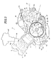
- the crank case 10 is splitted into two sections, i.e. the upper case 23 and the lower crank case 24, and the split plane A between the upper and lower crank cases 23 and 24 is inclined so that the front portion is lowered when the engine is mounted on the bicycle.
- the crank shaft 18 is disposed on the split plane A at a position frontal relative to a main shaft 32 and a drive shaft 35 of a transmission.
- the portion of the crank shaft 18 between the crank arms 18a and 18b is supported by a central bearing 19c, and the left and right end portions of the crank shaft 18 are supported by left and right bearings 19a and 19b.
- a front balancer shaft 47 extends parallel to the crank shaft 18 and is disposed in the lower crank case 24 at a position in front of the crank shaft 18, whereas a rear balancer shaft 48 extends parallel to the crank shaft 18 and is disposed in the upper crank case 23 at a position behind the crank shaft 18.
- the front balancer shaft 47 is thus positioned below the split plane A and the rear balancer shaft is positioned above the split plane A, and the line L connecting the center axis of the front-lower balancer shaft 47 and the center axis of the rear-upper balancer shaft 48 crosses the split plane A at a position in front of the center axis of the crank shaft 18, as best seen from Fig. 2.
- each of the front and rear balancer shafts 47, 48 comprises a balancer body 49, a support shaft 50 inserted through the balancer body 49 and needle bearings 51 disposed between the balancer body 49 and the support shaft 50.
- the support shaft 50 of the rear balancer shaft 48 is inserted through an opening 23b formed through the left side wall (as viewed in Fig. 3) of the upper crank case 23, and one end thereof is carried by a support opening 23c formed through the right side wall (as viewed in Fig. 3) of the upper crank case 23 and the other end thereof is secured to the left side wall of the upper crank case 23 by a keep plate 48b.
- the support shaft 50 of the front balancer shaft 47 is inserted through an opening 24f formed through the left side wall (as viewed in Fig. 4) of the lower crank case 24, and one end thereof is carried by a support opening 24g formed through the right side wall (as viewed in Fig. 4) of the lower crank case 24 and the other end thereof is secured to the left side wall of the lower crank case 24 by a keep plate 47b.
- the balancer body 49 comprises an integral cylinder 49a having weight segments 49b at the ends thereof and a positioner segment 49c at the substantial center thereof.
- the weight segments 49b are positioned in the spaces between the webs of the crank arms 18a, 18b of the crank shaft 18.
- the center positioner segment 49c extends above and below each of the balancer shafts 47, 48 to be received by guide ditches 52a of a positioner plate 52 which is fixed to the crank case 10, so that each of the balancer shafts 47, 48 is set in position along the axial direction.
- reference numeral 58 designates a bleezer cover defining a bleezer chamber, and the bleezer cover 58 may be removed to allow access into the upper crank case 23, for example, when the rear balancer shaft 48 is assembled.
- a transmission main shaft 32 (hereinafter referred to simply as “main shaft”) extends through the upper crank case 23 at a position behind the crank shaft 18 and above the split plane A, and a transmission drive shaft 35 (hereinafter referred to simply as “drive shaft”) is positioned on the split plane A and behind the main shaft 32.
- the line extending along the center axis of the cylinder and the line connecting the center axis of the crank shaft 18 with the center axis of the main shaft 32 form a first letter V having its opening at the upside
- the line connecting the center axis of the crank shaft 18 with the center axis of the main shaft 32 and the line connecting the center axis of the main shaft 32 with the center axis of the drive shaft 35 form a second letter V having its opening at the downside.
- a down draft type carburetor 65 is disposed above the space of the first letter V formed by the line extending along the center axis of the cylinder and the line connecting the center axis of the crank shaft 18 with the center axis of the main shaft 32, and an intake passage 66 is rising towards the carburetor 65 (see Fig. 2).
- the left and right ends of the main shaft 32 are carried by bearings 32b and 32c, and the ends of the drive shaft 35 are carried by bearings 35b and 35c.
- the right bearing 32c for the main shaft 32 is mounted through a housing 32d having a diameter larger than the diameter of a final drive gear 32a mounted on the main shaft 32 to the right side wall of the upper crank case 23.
- An opening is formed at the portion at which the left bearing 32b is arranged so that the main shaft 32 may be removed through the opening as desired, and this opening is closed by securing a cap 32e.
- the cap 32e and an oil seal 35d disposed on the outside face of the left bearing 35b of the drive shaft 35 are pressed by a metal pressing plate 35e which is fixedly secured to the left side wall of the crank case 10.
- a wet multi-plate clutch 33 is mounted on the right end (as viewed in Fig. 3) of the main shaft 32, and a spur gear 33b fixed to the clutch outer 33a of the clutch 33 meshes with a small spur gear 22 fixed to the crank shaft 18.
- the clutch 33 further comprises a pressing member 33c which is moved by a control shaft 33d.
- the control shaft 33d is inclined forwards from the vertical direction when viewed from the right side of the vehicle, and a clutch cable 33e extends behind the cylinder block 11 along the left side of the vehicle body in a manner so that it is not concaved towards the downside, the clutch cable 33e being connected to a left grip of the control handle (see Fig. 1).
- One of the transmission gears 32a mounted on the main shaft 32 meshes with one of the transmission gears 35a mounted on the drive shaft 35a to form a constant-mesh type transmission.
- the left end of the drive shaft 35 protrudes beyond the left side wall of the crank case 10, and a sprocket 36 for driving the rear wheel is mounted on the protruding end.
- a power transmission chain 37 runs around the sprocket 36 and a driven sprocket 5a of the rear wheel 5 (see Figs. 2 and 5).
- the outside of the sprocket 36 is covered by a chain cover 38 which serves to shield the chain 37 and the sprocket 36 to prevent sticking of splashes of mud (see Fig. 3).
- a shift pedal 39 is disposed below the drive sprocket 36 and connected through a link rod 41b, which has universal joints 41a at the ends thereof and extending vertically at the outside of the drive sprocket 36, to a shift shaft 40 disposed above the drive sprocket 36.
- the link rod 41b is covered by a case cover 42 (see Fig. 2).
- Pivot supports 24a are integrally formed at the rear end portions of the lower crank case 24 of the crank case 10.
- the front ends of the rear arms 6 are positioned outside of the pivot supports 24a and support brackets 2a of the frame 1 are positioned outside of the rear arms 6, a pivot shaft 24h being inserted through these members.
- the engine unit 9 is suspended and the rear arms 6 are pivoted by the pivot shaft 24h and the pivot supports 24a.
- Mounting means for mounting the engine 9 to the frame 2 are denoted by 62 and 63 in Figs. 2 and 3.
- reference numeral 43 designates a starter motor which is disposed in the lower crank case 24.
- the starter motor 43 has an output shaft 43a on which a drive gear 43b is mounted.
- the drive gear 43b meshes through an idle gear 45 with a starter gear 46 mounted on the crank shaft 18 through a one-way clutch.
- the main shaft 32 is disposed in the upper crank case 23 and the starter motor 43 is disposed in the space left vacant in the lower crank case, whereby the size of the engine is significantly reduced.
- the crank case 10 is splitted into the upper and lower crank cases 23, 24, the crank shaft 18 and the drive shaft 35 being disposed on the split plane and the main shaft 32 being disposed in the upper crank case 23 at a position between the crank shaft 18 and the drive shaft 35 and above the split plane A.
- the drive shaft 35 is positioned closer to the crank shaft 18 to decrease the length of the crank case correspondingly, whereby the size of the engine is reduced and the wheel base of the vehicle is also decreased.
- pivot supports 24a for pivotally carrying the rear arms 6 are formed integrally with the lower crank case 24 and the pivot supports 24a are carried by the support brackets 2a of the frame 2 together with the front ends of the rear arms 6, whereby the engine suspending point and the rear arm pivoting point are coincident with each other to contribute decrease in length of the wheel base.
- the main shaft 32 is disposed in the upper crank case 23 in the illustrated embodiment, the main shaft 32 may be disposed in the lower crank case.
- the pivot supports 24a are formed integrally with the lower crank case 24 in the illustrated embodiment, they may be formed integrally with the upper crank case 23 or may be formed such that the center axes thereof extend along the split plane A. Substantially equivalent effects as obtained by the illustrated embodiment can be obtained by arranging the main shaft 32 in the lower crank case 24 or by arranging the pivot supports 24a in the modified manner as described above.
Landscapes
- Engineering & Computer Science (AREA)
- Chemical & Material Sciences (AREA)
- Combustion & Propulsion (AREA)
- Mechanical Engineering (AREA)
- General Engineering & Computer Science (AREA)
- Cylinder Crankcases Of Internal Combustion Engines (AREA)
- Arrangement Of Transmissions (AREA)
- General Details Of Gearings (AREA)
Claims (12)
- Un moteur de véhicule monté à un endroit en face d'un bras arrière (6) qui est pivotable dans le sens vertical et présente une extrémité arrière portant au moins une roue arrière, comprenant un carter de moteur (10), un villebrequin (18), un arbre principal de transmission (32) et un arbre d'entraînement de transmission (35), dans lequel le carter de moteur (10) comporte une partie de carter de moteur supérieure (23) et une partie de carter de moteur inférieure (24) séparées l'une de l'autre par un plan de séparation (A) et dans lequel un villebrequin (18) et un arbre d'entraînement de transmission (35) sont disposés et portés sur le plan de séparation (A), entre la partie de carter de moteur supérieure (23) et la partie de carter de moteur inférieure (24), et s'étendent dans le sens de la largeur du châssis (2) du véhicule, caractérisé en ce que l'arbre principal de transmission (32) est disposé d'un côté du plan de séparation (A) et porté par l'une ou l'autre des parties de carter de moteur supérieure ou inférieure (23, 24).
- Un moteur de véhicule suivant la revendication 1, caractérisé en ce que l'arbre d'entraînement de transmission (35) est disposé derrière l'arbre principal de transmission (32) et dans lequel le bras arrière (6) présente un arbre pivot (24h) porté par un support pivot (24a) disposé dans la partie arrière du carter de moteur (10).
- Un moteur de véhicule suivant la revendication 2, caractérisé en ce que l'arbre principal de transmission (32) est disposé d'un premier côté du plan de séparation (A), entre les parties de carter de moteur supérieure ou inférieure (23, 24) et le support pivot (24a) est disposé du côté opposé au premier côté, au-delà du plan de séparation (A).
- Un moteur de véhicule suivant la revendication 1, caractérisé en ce que l'arbre principal de transmission (32) est disposé d'un premier côté du plan de séparation (A), un moteur de démarrage (43) étant disposé entre le villebrequin (18) et l'arbre d'entraînement de transmission (35) et du côté opposé au premier côté, au-delà du plan de séparation (A).
- Un moteur de véhicule suivant la revendication 1, caractérisé en ce qu'il comprend un arbre de changement de vitesse (40) disposé sur l'une ou l'autre des parties de carter de moteur supérieure ou inférieure (23, 24), par lequel est porté l'arbre principal de transmission (32).
- Un moteur de véhicule suivant la revendication 1, caractérisé en ce que le plan de séparation (A) entre les parties de carter de moteur supérieure ou inférieure (23, 24) est incliné, de sorte que la partie avant du carter de moteur (10) est plus basse que la partie arrière du carter de moteur (10).,
- Un moteur de véhicule suivant la revendication 6, caractérisé en ce que l'arbre principal de transmission (32) est disposé dans la partie de carter de moteur supérieure (23) et le support pivot est disposé dans la partie de carter de moteur inférieure (24).
- Un moteur de véhicule suivant la revendication 1, caractérisé en ce que la ligne s'étendant le long de l'axe de centre du cylindre (11) du moteur et la ligne reliant l'axe de centre de l'arbre principal de transmission (32) à l'axe de centre du villebrequin (18) sont inclinées vers le haut, de sorte que ces lignes forment une lettre V ayant son ouverture du côté supérieur, la ligne reliant l'axe de centre du villebrequin (18) à l'axe de centre de l'arbre principal de transmission (32) et la ligne reliant l'axe de centre de l'arbre principal de transmission (32) à l'axe de centre de l'arbre d'entraînement de transmission (35) étant inclinées vers le bas, de sorte que ces lignes forment une autre lettre V ayant son ouverture du côté inférieur.
- Un moteur de véhicule suivant la revendication 1, caractérisé en ce que le moteur est porté dans le voisinage du centre du châssis (2) du véhicule, que l'arbre principal de transmission (32) et l'arbre d'entraînement de transmission (35) sont disposés derrière le villebrequin (18), que la ligne s'étendant le long de l'axe de centre du cylindre (11) du moteur (9) et la ligne reliant l'axe de centre de l'arbre principal de transmission (32) à l'axe de centre du villebrequin (18) sont inclinées vers le haut, de manière que ces lignes forment une première lettre V ayant son ouverture du côté supérieur, que la ligne reliant l'axe de centre de l'arbre principal de transmission (32) à l'axe de centre du villebrequin (18) et la ligne reliant l'axe de centre de l'arbre principal de transmission (32) à l'axe de centre de l'arbre d'entraînement de transmission (35) sont inclinées vers le bas, de manière que ces lignes forment une seconde lettre V ayant son ouverture du côté inférieur et un passage d'entrée (66) s'étendant vers le bas. à partir d'un plan opposé à l'ouverture de la première lettre V, dans une chambre de combustion (14) du cylindre (11).
- Un moteur de véhicule suivant la revendication 1, caractérisé en ce que le moteur est porté dans le voisinage du centre du châssis (2) du véhicule, que l'arbre principal de transmission (32) et l'arbre d'entraînement de transmission (35) sont disposés derrière le villebrequin (18), que la ligne s'étendant le long de l'axe de centre du cylindre (11) du moteur (9) et la ligne reliant l'axe de centre de l'arbre principal de transmission (32) à l'axe de centre du villebrequin (18) sont inclinées vers le haut, de manière que ces lignes forment une première lettre V ayant son ouverture du côté supérieur, que la ligne reliant l'axe de centre de l'arbre principal de transmission (32) à l'axe de centre du villebrequin (18) et la ligne reliant l'axe de centre de l'arbre principal de transmission (32) à l'axe de centre de l'arbre d'entraînement de transmission (35) sont inclinées vers le bas, de manière que ces lignes forment une seconde lettre V ayant son ouverture du côté inférieur, un arbre balancier (48) étant disposé dans l'ouverture de la première lettre V et un autre arbre balancier (47) étant disposé sous le cylindre (11).
- Un moteur de véhicule suivant la revendication 10, caractérisé en ce que le carter de moteur (10) est divisé en une partie de carter de moteur supérieure (23) et une partie de carter de moteur inférieure (24), l'un des arbres balanciers (48) étant disposé dans la partie de carter de moteur supérieure (23) et l'autre arbre balancier (47) étant disposé dans la partie de carter de moteur inférieure (24).
- Un moteur de véhicule suivant la revendication 5, caractérisé en ce que l'arbre principal de transmission (32) et l'arbre de changement de vitesse (40) sont disposés dans la partie de carter de moteur supérieure (23), une pédale de changement de vitesse (39) étant disposée à l'extérieur de la partie de carter de moteur inférieure (24).
Applications Claiming Priority (4)
| Application Number | Priority Date | Filing Date | Title |
|---|---|---|---|
| JP266939/88 | 1988-10-21 | ||
| JP26693988A JP2670109B2 (ja) | 1988-10-21 | 1988-10-21 | エンジン |
| JP63266941A JP2744444B2 (ja) | 1988-10-21 | 1988-10-21 | エンジンのバランサ軸取付装置 |
| JP266941/88 | 1988-10-21 |
Publications (2)
| Publication Number | Publication Date |
|---|---|
| EP0369618A1 EP0369618A1 (fr) | 1990-05-23 |
| EP0369618B1 true EP0369618B1 (fr) | 1994-10-05 |
Family
ID=26547655
Family Applications (1)
| Application Number | Title | Priority Date | Filing Date |
|---|---|---|---|
| EP89310884A Expired - Lifetime EP0369618B1 (fr) | 1988-10-21 | 1989-10-23 | Moteur pour véhicule |
Country Status (3)
| Country | Link |
|---|---|
| US (1) | US5078105A (fr) |
| EP (1) | EP0369618B1 (fr) |
| DE (1) | DE68918668T2 (fr) |
Families Citing this family (31)
| Publication number | Priority date | Publication date | Assignee | Title |
|---|---|---|---|---|
| US5186078A (en) * | 1991-03-19 | 1993-02-16 | Mazda Motor Corporation | Engine unit |
| DE69404782T2 (de) * | 1993-08-30 | 1997-12-04 | Honda Motor Co Ltd | Ölzufuhrkonstruktion für Anlassräder in einer Brennkraftmaschine |
| US5564379A (en) * | 1994-06-01 | 1996-10-15 | Volkswagen Ag | Arrangement for balancing varying moments |
| CA2153721C (fr) * | 1994-07-13 | 2003-12-02 | Takashi Shichinohe | Prise de force pour vehicule |
| DE69618865T2 (de) * | 1995-07-17 | 2002-06-06 | Yamaha Hatsudoki K.K., Iwata | Brennkraftmaschine mit Balanciersystem |
| JP3553217B2 (ja) * | 1995-07-17 | 2004-08-11 | ヤマハ発動機株式会社 | 4サイクルエンジン |
| DE29713785U1 (de) * | 1997-08-02 | 1997-10-02 | P.I.V. Antrieb Werner Reimers Gmbh & Co Kg, 61352 Bad Homburg | Getriebe für Doppelschneckenextruder |
| JP2001071771A (ja) * | 1999-09-03 | 2001-03-21 | Honda Motor Co Ltd | 内燃機関のパワーユニット |
| JP4160242B2 (ja) * | 2000-09-12 | 2008-10-01 | 本田技研工業株式会社 | エンジンの動力伝達構造 |
| JP2002266653A (ja) | 2001-03-09 | 2002-09-18 | Yamaha Motor Co Ltd | 雪上車 |
| JP2002276596A (ja) | 2001-03-14 | 2002-09-25 | Yamaha Motor Co Ltd | 渦巻ポンプ |
| RU2221926C2 (ru) * | 2002-03-04 | 2004-01-20 | Сибирский государственный технологический университет | Двигатель-редуктор |
| AU2003242111A1 (en) * | 2002-06-10 | 2003-12-22 | Yamaha Hatsudoki Kabushiki Kaisha | Blow-by gas reduction device for engine of saddle riding- type motor vehicle |
| US6929081B2 (en) * | 2002-08-13 | 2005-08-16 | Brp-Rotax Gmbh & Co. Kg | Engine arrangement for a four cycle engine |
| US6941920B1 (en) * | 2004-04-02 | 2005-09-13 | Kenneth R. Thurm | Motorcycle engine and transmission interbracing member |
| JP4431017B2 (ja) * | 2004-09-29 | 2010-03-10 | 本田技研工業株式会社 | 二次空気供給装置 |
| JP4563824B2 (ja) * | 2005-01-18 | 2010-10-13 | 本田技研工業株式会社 | 自動二輪車用エンジン |
| JP4754276B2 (ja) * | 2005-06-17 | 2011-08-24 | 川崎重工業株式会社 | 自動二輪車 |
| JP2007009737A (ja) * | 2005-06-28 | 2007-01-18 | Kawasaki Heavy Ind Ltd | エンジンの軸配置構造 |
| JP4595784B2 (ja) * | 2005-09-25 | 2010-12-08 | スズキ株式会社 | 自動二輪車のエンジンおよびその組立方法 |
| JP4725285B2 (ja) * | 2005-09-25 | 2011-07-13 | スズキ株式会社 | 自動二輪車のエンジン |
| TW200726698A (en) * | 2005-09-30 | 2007-07-16 | Honda Motor Co Ltd | Scooter type vehicle |
| JP4636506B2 (ja) * | 2006-02-28 | 2011-02-23 | 本田技研工業株式会社 | 車両用発電機の冷却構造 |
| JP4620619B2 (ja) * | 2006-03-27 | 2011-01-26 | 本田技研工業株式会社 | 小型車両用内燃機関 |
| JP2008068429A (ja) * | 2006-09-12 | 2008-03-27 | Fuji Xerox Co Ltd | 記録装置 |
| EP2031210A3 (fr) * | 2007-08-31 | 2013-04-17 | Yamaha Hatsudoki Kabushiki Kaisha | Moteur et véhicule de type chariot cavalier |
| JP4608536B2 (ja) * | 2007-11-30 | 2011-01-12 | 本田技研工業株式会社 | 自動二輪車用パワーユニット |
| JP5728182B2 (ja) * | 2010-09-06 | 2015-06-03 | 川崎重工業株式会社 | シリンダ傾斜型エンジン |
| JP5750430B2 (ja) * | 2012-12-26 | 2015-07-22 | 本田技研工業株式会社 | 車載内燃機関のケーシング構造 |
| JP6601147B2 (ja) * | 2015-10-27 | 2019-11-06 | スズキ株式会社 | エンジンのバランサ装置及び自動二輪車 |
| DE102016215191A1 (de) * | 2016-08-16 | 2018-02-22 | Zf Friedrichshafen Ag | Getriebeanordnung mit einem Gehäuse aus Druckguss |
Family Cites Families (15)
| Publication number | Priority date | Publication date | Assignee | Title |
|---|---|---|---|---|
| AT311130B (de) * | 1970-11-27 | 1973-10-25 | List Hans | Einspritzbrennkraftmaschine, insbesondere Einzylindermotor |
| JPS5840055B2 (ja) * | 1975-10-17 | 1983-09-02 | ダイハツ工業株式会社 | エンジンノ バランスソウチ |
| US4331212A (en) * | 1977-10-25 | 1982-05-25 | Honda Giken Kogyo Kabushiki Kaisha | Motorized two-wheeled vehicle |
| US4223567A (en) * | 1978-04-03 | 1980-09-23 | Honda Giken Kogyo Kabushiki Kaisha | Power transmission apparatus |
| JPS5572630A (en) * | 1978-11-24 | 1980-05-31 | Yamaha Motor Co Ltd | Vehicle engine |
| JPS56118506A (en) * | 1980-02-21 | 1981-09-17 | Yamaha Motor Co Ltd | Cylinder block of v-engine with over head cam shaft |
| US4550794A (en) * | 1981-01-14 | 1985-11-05 | Honda Giken Kogyo Kabushiki Kaisha | Motorcycle having an engine with a supercharger |
| JPS5822723A (ja) * | 1981-08-03 | 1983-02-10 | Yamaha Motor Co Ltd | 自動二輪車 |
| JPS5839863A (ja) * | 1981-09-03 | 1983-03-08 | Yamaha Motor Co Ltd | エンジンのバランサ装置 |
| JPS5965643A (ja) * | 1982-10-06 | 1984-04-13 | Honda Motor Co Ltd | 自動2輪車用エンジンのバランサ |
| DE3326321A1 (de) * | 1983-07-21 | 1985-01-31 | Dr.Ing.H.C. F. Porsche Ag, 7000 Stuttgart | Brennkraftmaschine |
| GB8324103D0 (en) * | 1983-09-08 | 1983-10-12 | Mitchell S W | Balancing system |
| JPS6069251A (ja) * | 1983-09-26 | 1985-04-19 | Yamaha Motor Co Ltd | 自動二輪車用エンジンの変速装置 |
| JP2647823B2 (ja) * | 1984-07-31 | 1997-08-27 | ヤマハ発動機株式会社 | 自動二輪車 |
| EP0281693B1 (fr) * | 1987-03-10 | 1991-10-09 | National Research Development Corporation | Composants pour véhicules automobiles |
-
1989
- 1989-10-23 EP EP89310884A patent/EP0369618B1/fr not_active Expired - Lifetime
- 1989-10-23 US US07/424,985 patent/US5078105A/en not_active Expired - Lifetime
- 1989-10-23 DE DE68918668T patent/DE68918668T2/de not_active Expired - Lifetime
Non-Patent Citations (2)
| Title |
|---|
| Honda CBX 1050 Engine Service Manual; Sections 10 (Crankcase) and 11 (oil pump) * |
| Technische Universität Graz; Mitteilung des Institutes für Verbrennungskraftmaschinen und Thermodynamic; Heft 31b Bildteil; Kenndaten und Konstruktion neuzeitlicher Zweiradmotoren 1982 * |
Also Published As
| Publication number | Publication date |
|---|---|
| DE68918668T2 (de) | 1995-05-04 |
| EP0369618A1 (fr) | 1990-05-23 |
| US5078105A (en) | 1992-01-07 |
| DE68918668D1 (de) | 1994-11-10 |
Similar Documents
| Publication | Publication Date | Title |
|---|---|---|
| EP0369618B1 (fr) | Moteur pour véhicule | |
| JP4384457B2 (ja) | エンジン | |
| EP1178193B1 (fr) | Moteur à combustion interne pour moto | |
| US6427796B1 (en) | Rear wheel suspension system of motorcycle | |
| US5309877A (en) | Outboard engine assembly and internal combustion engine therefore | |
| EP0705966B1 (fr) | Moteur vertical | |
| US8662253B2 (en) | Lubricating oil feeding structure | |
| JP2674805B2 (ja) | 変速装置のリンク機構 | |
| US6557516B2 (en) | Engine unit for a vehicle | |
| JP3904703B2 (ja) | 小型船 | |
| EP0849450B1 (fr) | Moteur à combustion interne vertical | |
| JP2860793B2 (ja) | 自動二輪車用エンジンの2軸式バランサ装置 | |
| US7438031B2 (en) | Layout structure of hydraulic control valve for valve train in internal combustion engine | |
| JP2002021989A (ja) | 自動二輪車用エンジンの冷却装置 | |
| JP2002019682A (ja) | 自動二輪車用エンジンの動力伝達装置 | |
| US6848411B2 (en) | Secondary balancer of vertical engine of outboard motor | |
| JP2670109B2 (ja) | エンジン | |
| US6374795B2 (en) | Engine | |
| US10302004B2 (en) | Water pump unit | |
| EP1577584A2 (fr) | Dispositif de transmission de force et méthode pour l'assembler et voiture munie du dispositif | |
| US6186844B1 (en) | Outboard motor | |
| JP3866556B2 (ja) | エンジンにおけるオイルポンプ取付け構造 | |
| JP2744444B2 (ja) | エンジンのバランサ軸取付装置 | |
| JP2002021879A (ja) | エンジンの遠心式クラッチ装置 | |
| JP2726452B2 (ja) | エンジンのセルモータ配置構造 |
Legal Events
| Date | Code | Title | Description |
|---|---|---|---|
| PUAI | Public reference made under article 153(3) epc to a published international application that has entered the european phase |
Free format text: ORIGINAL CODE: 0009012 |
|
| AK | Designated contracting states |
Kind code of ref document: A1 Designated state(s): DE ES FR GB IT |
|
| 17P | Request for examination filed |
Effective date: 19900712 |
|
| 17Q | First examination report despatched |
Effective date: 19921022 |
|
| GRAA | (expected) grant |
Free format text: ORIGINAL CODE: 0009210 |
|
| AK | Designated contracting states |
Kind code of ref document: B1 Designated state(s): DE ES FR GB IT |
|
| PG25 | Lapsed in a contracting state [announced via postgrant information from national office to epo] |
Ref country code: IT Free format text: LAPSE BECAUSE OF FAILURE TO SUBMIT A TRANSLATION OF THE DESCRIPTION OR TO PAY THE FEE WITHIN THE PRESCRIBED TIME-LIMIT;WARNING: LAPSES OF ITALIAN PATENTS WITH EFFECTIVE DATE BEFORE 2007 MAY HAVE OCCURRED AT ANY TIME BEFORE 2007. THE CORRECT EFFECTIVE DATE MAY BE DIFFERENT FROM THE ONE RECORDED. Effective date: 19941005 |
|
| REF | Corresponds to: |
Ref document number: 68918668 Country of ref document: DE Date of ref document: 19941110 |
|
| ET | Fr: translation filed | ||
| PG25 | Lapsed in a contracting state [announced via postgrant information from national office to epo] |
Ref country code: ES Free format text: LAPSE BECAUSE OF FAILURE TO SUBMIT A TRANSLATION OF THE DESCRIPTION OR TO PAY THE FEE WITHIN THE PRESCRIBED TIME-LIMIT Effective date: 19950116 |
|
| PLBE | No opposition filed within time limit |
Free format text: ORIGINAL CODE: 0009261 |
|
| STAA | Information on the status of an ep patent application or granted ep patent |
Free format text: STATUS: NO OPPOSITION FILED WITHIN TIME LIMIT |
|
| 26N | No opposition filed | ||
| PGFP | Annual fee paid to national office [announced via postgrant information from national office to epo] |
Ref country code: ES Payment date: 19971031 Year of fee payment: 9 |
|
| REG | Reference to a national code |
Ref country code: GB Ref legal event code: IF02 |
|
| PGFP | Annual fee paid to national office [announced via postgrant information from national office to epo] |
Ref country code: DE Payment date: 20081016 Year of fee payment: 20 |
|
| PGFP | Annual fee paid to national office [announced via postgrant information from national office to epo] |
Ref country code: FR Payment date: 20081014 Year of fee payment: 20 |
|
| PGFP | Annual fee paid to national office [announced via postgrant information from national office to epo] |
Ref country code: GB Payment date: 20081022 Year of fee payment: 20 |
|
| REG | Reference to a national code |
Ref country code: GB Ref legal event code: PE20 Expiry date: 20091022 |
|
| PG25 | Lapsed in a contracting state [announced via postgrant information from national office to epo] |
Ref country code: GB Free format text: LAPSE BECAUSE OF EXPIRATION OF PROTECTION Effective date: 20091022 |