EP0369634A1 - Schneideinrichtung - Google Patents
Schneideinrichtung Download PDFInfo
- Publication number
- EP0369634A1 EP0369634A1 EP89311200A EP89311200A EP0369634A1 EP 0369634 A1 EP0369634 A1 EP 0369634A1 EP 89311200 A EP89311200 A EP 89311200A EP 89311200 A EP89311200 A EP 89311200A EP 0369634 A1 EP0369634 A1 EP 0369634A1
- Authority
- EP
- European Patent Office
- Prior art keywords
- blade
- article
- cutting blade
- cutting
- leading edge
- Prior art date
- Legal status (The legal status is an assumption and is not a legal conclusion. Google has not performed a legal analysis and makes no representation as to the accuracy of the status listed.)
- Withdrawn
Links
- 238000005520 cutting process Methods 0.000 title claims abstract description 56
- 230000007246 mechanism Effects 0.000 title description 2
- 230000006872 improvement Effects 0.000 claims abstract description 5
- 230000000694 effects Effects 0.000 claims description 3
- 239000000463 material Substances 0.000 description 8
- 239000002648 laminated material Substances 0.000 description 5
- 238000010030 laminating Methods 0.000 description 2
- 239000002184 metal Substances 0.000 description 2
- 238000009966 trimming Methods 0.000 description 2
- 238000011144 upstream manufacturing Methods 0.000 description 2
- 229910001369 Brass Inorganic materials 0.000 description 1
- 230000009471 action Effects 0.000 description 1
- 230000001154 acute effect Effects 0.000 description 1
- 239000010951 brass Substances 0.000 description 1
- 230000003247 decreasing effect Effects 0.000 description 1
- 230000007812 deficiency Effects 0.000 description 1
- 238000010586 diagram Methods 0.000 description 1
- 230000006870 function Effects 0.000 description 1
- 238000010348 incorporation Methods 0.000 description 1
- 230000009467 reduction Effects 0.000 description 1
- 239000004065 semiconductor Substances 0.000 description 1
- 230000035945 sensitivity Effects 0.000 description 1
- 239000002699 waste material Substances 0.000 description 1
Images

Classifications
-
- B—PERFORMING OPERATIONS; TRANSPORTING
- B26—HAND CUTTING TOOLS; CUTTING; SEVERING
- B26D—CUTTING; DETAILS COMMON TO MACHINES FOR PERFORATING, PUNCHING, CUTTING-OUT, STAMPING-OUT OR SEVERING
- B26D5/00—Arrangements for operating and controlling machines or devices for cutting, cutting-out, stamping-out, punching, perforating, or severing by means other than cutting
- B26D5/20—Arrangements for operating and controlling machines or devices for cutting, cutting-out, stamping-out, punching, perforating, or severing by means other than cutting with interrelated action between the cutting member and work feed
- B26D5/26—Arrangements for operating and controlling machines or devices for cutting, cutting-out, stamping-out, punching, perforating, or severing by means other than cutting with interrelated action between the cutting member and work feed wherein control means on the work feed means renders the cutting member operative
-
- B—PERFORMING OPERATIONS; TRANSPORTING
- B26—HAND CUTTING TOOLS; CUTTING; SEVERING
- B26D—CUTTING; DETAILS COMMON TO MACHINES FOR PERFORATING, PUNCHING, CUTTING-OUT, STAMPING-OUT OR SEVERING
- B26D7/00—Details of apparatus for cutting, cutting-out, stamping-out, punching, perforating, or severing by means other than cutting
- B26D7/01—Means for holding or positioning work
- B26D7/015—Means for holding or positioning work for sheet material or piles of sheets
Definitions
- the present invention relates generally to a laminated sheet trimmer. More specifically, the invention relates to a trimming machine or apparatus having a pivotable cutting blade to ensure that the edges of the laminate are cut parallel with the leading or trailing edge of the laminated article.
- the use of laminating machines to apply laminate material to such items as menus, place mats, and the like for their protection and increased durability has been common practice for many years.
- the discrete articles are laminated to a single, continuous web of the polymeric laminate sheet material.
- the borders or margins of adjacent or successive articles are overlapped, forming a continuous web of laminated articles.
- the trailing edge of an opaque first article is separated from the leading edge of an opaque second article by the transparent laminate sheet material.
- Cutting and trimming machines using cutting blades are used to slit the laminate sheet material and separate the articles.
- a light source and a light sensing device are placed on opposite sides of the continuous web of laminated articles.
- the light source and light sensing device are placed at a location proximate the cutting blade.
- the light beam is interrupted.
- the transparent laminate material passes between the light source and the light sensing device, the light beam is received by the sensing device. This characteristic is used by electronic control devices to trigger the cutting action of the blade at an appropriate time.
- the edge of the transparent laminate material is cut parallel to the leading or trailing edge of the underlying article. It is thus important that the web being fed to the blade is perpendicular to that blade. The path of the web can occasionally be offset from this preferred path, however. As a result, standard blades will not cut the laminate material parallel to the leading edge of the article. Rather, that blade will cut the web at a slight, acute angle to the leading or trailing edge.
- the prior art apparatus which cuts the web into discrete articles includes provisions for correcting such web offset conditions.
- An example of such correcting means is metal guides upstream of the cutting blade. These guides are spaced apart from each other at a distance which corresponds to the width of the web. Thus, they abut against the edges of the web as the web is fed towards the blade. The guides can be adjusted several degrees, to thereby force those edges and the entire web in the proper direction.
- the invention is an apparatus for parallel cutting of the laminated edge of a previously laminated article.
- the apparatus includes a cutting blade oriented substantially perpendicularly to the path of the article as it passes under that blade. It also comprises means for advancing that article to and beyond that blade.
- the improvement comprises three elements, in combination.
- the first is a plurality of sensing means for determining the extent of deviation of the leading edge of the article from parallelism with the cutting blade.
- the second is electronic feedback means communicative with the sensing means.
- the electronic feedback means determine the extent of rotation of the cutting blade necessary so that the blade will be reoriented into parallelism with the leading edge of the article.
- blade positioning means are provided, which are communicative with the electronic feedback means.
- the blade positioning means rotate the cutting blade to a position where that blade is parallel to the leading edge of the article.
- This apparatus provides for parallel cutting of the laminated edge of a previously laminated article in a manner to be described.
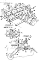
- the apparatus includes a cutting blade 14 oriented substantially perpendicularly to the path of the laminated article 16a ( Figure 2) as it passes under that blade.
- the article 16a is one of many articles 16b, 16c, and so forth, that have been laminated together to form a single, continuous web 18 of the polymeric laminate sheet material.
- the apparatus also comprises means for advancing that article 16a and that web 18 to and beyond that blade 14.
- that means includes a pair of drive rollers 20 and 22 upstream of the cutting blade 14, and an idler roller 24 downstream of that blade 14.
- the drive rollers 20 and 22 and the idler roller 24 are all indirectly driven by a step motor, as will be described later.
- the step motor driving rollers 20, 22, and 24 is a type 34T2BEHD, model no. 2434, and is manufactured by Bodine Electric Company.
- This motor without accompanying motor drives that are provided with this embodiment, is geared for 200 steps per revolution.
- the improvement comprises three elements, in combination.
- the first is a plurality of sensing means for determining the extent of deviation of the leading edge of the article from parallelism with the cutting blade.
- these sensing means comprise a pair of infrared light beams 26 and 28 and a pair of corresponding light detectors 30 and 32.
- each of the infrared light beams 26 and 28 are secured within a frame 34, and are disposed on one side of the plane of the web 18. A line between the centers of those beams 26 and 28 is parallel to the cutting edge 36 of the cutting blade 14, when that blade is in a "zero" or “reference” position.
- Each of the sensors 30 and 32 are secured to another portion of the frame 34. The part of the frame to which the sensors 30 and 32 are secured is separated by the plane of the web 18 from the part of the frame to which the light beams 26 and 28 are secured.
- light from these light beams 26 and 28 will be detected by sensors 30 and 32 when the transparent laminate border material 54 that connects the articles (e.g., 16a and 16b) is disposed directly between the beams and sensors.
- the opaque article 16a passes between the beam and the sensors, the light beam is interrupted, i.e., no light reaches the sensor.
- leading edge 38 of article 16a When the leading edge 38 of article 16a is perfectly parallel with the cutting edge 36 of the blade 14 in the "zero" or “reference” position, the leading edge 38 will interrupt the beam of light from beam 26 to sensor 30 at precisely the same time as it interrupts the beam of light from beam 28 to sensor 32. However, in the event that the leading edge 38 of article 16a is somewhat offset from perfect parallelism with the cutting edge one of the light beams will be interrupted sooner than the other. It is this difference in the time of light beam interruption that triggers the mechanisms rotating the cutting blade 14.
- this Figure depicts an article 16a that is offset from perfect parallelism with the blade 14 in the "zero" position.
- the extent of offset depicted in this Figure is exaggerated for purposes of this description.
- the beam of light provided by infrared light beam 28 to light detector 32 is interrupted by the leading edge 38 of article 16a.
- the light beam from infrared light beam 26 to light detector 30 is not interrupted, however, until the drive rollers 20 and 22 move the article 16a somewhat further ahead.
- step motor 40 revolves through one step, article 16a is moved forward 0.010" (ten-thousandths of an inch) in the present embodiment.
- a signal from this step motor is sent to the second component of the system, the electronic feedback means, for each "step” moved by the motor 40 in the time interval between the interruption of these respective beams.
- the second element of the present invention is the electronic feedback means communicative with the sensing means and the step motor.
- the electronic feedback means determine the extent of rotation of the cutting blade 14 necessary so that the blade is oriented parallel to the leading edge 38 of the article 16a prior to cutting the laminate material.
- a 110-volt, alternating current unswitched power source 42 is provided to power controller 44.
- a transformer 43 provides stepped-down, direct-current power for step motor 40 and a second, smaller step motor 46.
- This smaller step motor 46 which will be fully described later, effects movement of the cutting blade 14.
- Motor 46 is also manufactured by Bodine, as model no. 2431.
- roller step motor 40 and blade step motor 46 are provided with a roller motor drive 48 and a blade motor drive 50, respectively.
- Roller motor drive 48 also provides gearing effecting a 2:1 reduction, which effectively renders motor 40 a 400 step per revolution motor.
- the roller motor drive 48 and the blade motor drive 50 both accept a "step” signal.
- the blade motor drive 50 also accepts a "direction” signal.
- the "step” signal from the controller signals each motor, and particularly the blade motor, to move a designated number of steps.
- the "direction” signal from the controller signals the movement of the blade motor, and ultimately the blade, in the desired clockwise or counterclockwise direction.
- the display/keyboard 52 provides a means for user interface. It enables the user to turn the apparatus on and off, adjust its speed, control the length of the articles being cut, and establish the size of the laminate border, if any, surrounding the article.
- the interruption and reception of light from infrared light beams (LED) 26 and 28 and their respective detectors (RCVR.) 30 and 32 is detected and determined by the controller 44.
- the detectors are phototransistors. As indicated above, these detectors 30 and 32: (1) detect the interruption of light from the infrared light beams 26 and 28 when an article (16a, 16b, or 16c) is disposed between the detectors and the light beams; (2) detect light from the infrared light beams 26 and 28 when transparent laminate border material 54 is disposed between the detectors and the light beams.
- the apparatus 12 is used with articles, such as sheets, of various widths.
- the apparatus can best ensure accurate cutting by placing the light beams and their associated detectors as far away from each other as possible. For example, with a 8 1/2" wide sheet, the light beams and detectors are best placed about 7" apart. With a 14" wide sheet, however, the light beams and detectors are best placed about 12"-13" apart.
- At least one of the light beams and one of the light detectors is movable.
- sheets of these and other varied widths can best be accommodated.
- infrared light beam or 28 and its corresponding light detector or "eye” 32 may be movable into any one of three positions.
- the controller 44 may include a manually-operable "eye" position switch 56 for moving beam 28 and "eye" 32 to any one of these positions.
- the apparatus 12 would include several fixed light beams and their corresponding "eyes.” Each beam/detector or beam/eye set would be along a line parallel to the blade 14 in its "zero" position.
- the controller 44 would determine the appropriate pair of beam/eye sets for a given article width. Particularly, components that are communicative with the controller 44 would sense the width of the article 16 passing through apparatus 12 and select the two light beam/eye sets most suitable for that width.
- a blade home sensor 58 is provided.
- the blade home sensor 58 is adjacent the cutting blade 14 and determines its position. Particularly, the blade home sensor 58 in combination with the controller 44 determine the angular position of the blade at any given time.
- the controller includes a bale switch 60. This switch 60 is coupled to a bale arm (not shown). The bale arm and switch regulate the relative speeds of the laminating apparatus (not shown) and the cutting apparatus 12 that it feeds.
- a cylinder bottom switch 66 and a cylinder top switch 68 are provided to indicate to the controller 44 the positions of the cylinders.
- the cylinder bottom switch 66 provides a signal to the controller 44 the instant a cylinder 62 or 64 has reached the bottom of its travel. This instant corresponds to the blade 14 reaching its lowermost position.
- the switches may be located at any desirable position, such as on the cylinder.
- the controller 44 powers air cylinders 62 and 64 to move the blade upward into its normal, uppermost position.
- cylinder top switch 68 sends its own signal to controller 44.
- the controller 44 restarts the drive rollers 20 and 22.
- the output signals of a microprocessor 70 (no. COP 402N, manufactured by National Semiconductor) control the motors and other components of the apparatus 12.
- the microprocessor 70 itself is controlled by a software program entered into an EPROM 72, or electronically programmable read-only memory.
- the software program which is entered into this EPROM is attached as an integral part of this specification, appearing immediately before the claims.
- the controller 44 also includes a sensitivity switch 74.
- This switch 74 is adjustable, and regulates the amount of light that must be sensed by detectors 30 and 32 corresponding to the "light received" condition.
- This switch 74 accounts for articles 16 that may be very thin and of relatively low opacity. It also accounts for varying thicknesses and transparencies of the transparent laminate border material 54.
- blade positioning means are provided as the third component of the present apparatus.
- the blade positioning means are communicative with the electronic feedback means. Blade positioning means rotate the cutting blade 14 to a position where that blade is parallel to the leading edge of the article.
- the blade positioning means can best be viewed in Figure 3. Included are blade motor 46 and blade motor drive 50. As indicated above, blade motor 46 and its associated motor drive 50 provide 200 discrete steps per motor revolution.
- the output shaft of motor 46 is a ball screw 76 or threaded drive shaft connected at its end to a rotatable portion 78 of frame 34. This rotatable portion 78 pivots about a pivot point comprising, at the top, a brass bushing 80 held in place with a set screw 82 ( Figure 1). At the bottom, the pivot point is defined shaft and thrust bearing assembly. Particularly, a 5/8" shaft 84 is reduced at its end to 3/8" in diameter, and this reduced end is rotatable in an Andrews W-3/8" ball and roller bearing 86.
- one step of the motor 40 moves both rollers 20 and 22 and article 16a forward 0.010". It will be obvious to the skilled artisan that these figures will vary according to the diameter of the rollers used. It will also be obvious to the skilled artisan that the time difference for offset article 16a to break light beam 26 and light beam 28 will depend on the spacing of the light beams from each other.
- this apparatus 12 can be used for cutting the article 16a at either its leading edge 38 or its trailing edge 88.
- the apparatus 12 does not assume that the leading 38 and trailing edges 88 are offset the same number of degrees. Accordingly, the apparatus 12 will calculate, in the manner described above, two numbers that are stored in the memory of the microprocessor. The first is the offset angle of the leading edge 38, and the second is the offset angle of the trailing edge 88.
- the computed angle is strictly a function of the number of steps that the motor moves forward between the time the first and second light beams are interrupted, and the distance between the two light beams.
- the blade 14 must be turned by blade motor 46 enough to "cancel" the angle of edges 38 or 88 to the blade 14.
- the extent and direction of rotation of the threaded drive shaft 76 is determined by the pitch of its threads, the current angle of the blade 14, as read by blade home sensor 58, and the offset of the leading 38 or trailing edges 88 with the blade 14.
- the apparatus 12 in accordance with this embodiment can easily handle the cuts on the leading and trailing edges of forty articles or more per minute. Thus, eighty adjustments of the angle of cutting blade 14 per minute can be easily handled.
Landscapes
- Life Sciences & Earth Sciences (AREA)
- Forests & Forestry (AREA)
- Engineering & Computer Science (AREA)
- Mechanical Engineering (AREA)
- Details Of Cutting Devices (AREA)
Applications Claiming Priority (2)
| Application Number | Priority Date | Filing Date | Title |
|---|---|---|---|
| US27105488A | 1988-11-14 | 1988-11-14 | |
| US271054 | 1988-11-14 |
Publications (1)
| Publication Number | Publication Date |
|---|---|
| EP0369634A1 true EP0369634A1 (de) | 1990-05-23 |
Family
ID=23034008
Family Applications (1)
| Application Number | Title | Priority Date | Filing Date |
|---|---|---|---|
| EP89311200A Withdrawn EP0369634A1 (de) | 1988-11-14 | 1989-10-30 | Schneideinrichtung |
Country Status (1)
| Country | Link |
|---|---|
| EP (1) | EP0369634A1 (de) |
Cited By (1)
| Publication number | Priority date | Publication date | Assignee | Title |
|---|---|---|---|---|
| CN108018703A (zh) * | 2016-11-02 | 2018-05-11 | 天津太卡科技发展有限公司 | 一种高效自动裁剪机 |
Citations (2)
| Publication number | Priority date | Publication date | Assignee | Title |
|---|---|---|---|---|
| US4555967A (en) * | 1982-08-17 | 1985-12-03 | Societe Nationale Industrielle Et Aerospatiale | Machine for cutting pieces from a band material |
| EP0251802A1 (de) * | 1986-07-02 | 1988-01-07 | Hamamatsu Manufactory, Ltd. | Schneidmechanismus |
-
1989
- 1989-10-30 EP EP89311200A patent/EP0369634A1/de not_active Withdrawn
Patent Citations (2)
| Publication number | Priority date | Publication date | Assignee | Title |
|---|---|---|---|---|
| US4555967A (en) * | 1982-08-17 | 1985-12-03 | Societe Nationale Industrielle Et Aerospatiale | Machine for cutting pieces from a band material |
| EP0251802A1 (de) * | 1986-07-02 | 1988-01-07 | Hamamatsu Manufactory, Ltd. | Schneidmechanismus |
Cited By (1)
| Publication number | Priority date | Publication date | Assignee | Title |
|---|---|---|---|---|
| CN108018703A (zh) * | 2016-11-02 | 2018-05-11 | 天津太卡科技发展有限公司 | 一种高效自动裁剪机 |
Similar Documents
| Publication | Publication Date | Title |
|---|---|---|
| US5079981A (en) | Cutter mechanism | |
| US5074178A (en) | Apparatus and method for cutting drawings from a web of sheet material | |
| US5765460A (en) | Paper cutter for variable format | |
| US5447486A (en) | Maintaining perforation phasing | |
| CA1291011C (en) | Slicing machine | |
| US4945797A (en) | Automated multiple rip saw feeding apparatus | |
| US6021629A (en) | Registration system for sealed tray packaging machine | |
| US4699027A (en) | Cable stripping apparatus | |
| JPH07237812A (ja) | ローラ間隙間調整装置 | |
| EP0355026B1 (de) | Selbsttätige Bahnzuführvorrichtung | |
| EP2188097B1 (de) | Messerhalter | |
| EP0369634A1 (de) | Schneideinrichtung | |
| EP0414796A1 (de) | Zeichen- oder schneidvorrichtung des plottentyps mit mitteln zur förderung des arbeitsbandes von einer zufuhrbobine | |
| US3611856A (en) | Web cutter | |
| US6860481B2 (en) | Sheet stacking device | |
| US3743155A (en) | Apparatus for feeding sheet material | |
| JP4446534B2 (ja) | 断裁機 | |
| JPH0433596B2 (de) | ||
| CN223254495U (zh) | 定位纠偏系统及涂布设备 | |
| JPH0623689A (ja) | ラミネート枚葉紙のカッター構造 | |
| WO2001076832A1 (en) | Cutting device for sheet laminator | |
| EP0109799A1 (de) | Ausdehnungssteuerung in einer Laminiervorrichtung | |
| JP2724487B2 (ja) | 連続用紙切断装置 | |
| JP3167860B2 (ja) | 裁断装置 | |
| US4539752A (en) | Automatic sheet transport mechanism |
Legal Events
| Date | Code | Title | Description |
|---|---|---|---|
| PUAI | Public reference made under article 153(3) epc to a published international application that has entered the european phase |
Free format text: ORIGINAL CODE: 0009012 |
|
| AK | Designated contracting states |
Kind code of ref document: A1 Designated state(s): AT BE CH DE ES FR GB GR IT LI LU NL SE |
|
| STAA | Information on the status of an ep patent application or granted ep patent |
Free format text: STATUS: THE APPLICATION IS DEEMED TO BE WITHDRAWN |
|
| 18D | Application deemed to be withdrawn |
Effective date: 19901126 |