EP0369704A2 - Dispositif d'accouplement à friction pour pièces d'horlogerie - Google Patents
Dispositif d'accouplement à friction pour pièces d'horlogerie Download PDFInfo
- Publication number
- EP0369704A2 EP0369704A2 EP89311708A EP89311708A EP0369704A2 EP 0369704 A2 EP0369704 A2 EP 0369704A2 EP 89311708 A EP89311708 A EP 89311708A EP 89311708 A EP89311708 A EP 89311708A EP 0369704 A2 EP0369704 A2 EP 0369704A2
- Authority
- EP
- European Patent Office
- Prior art keywords
- pinion
- wheel
- shaft member
- toothed wheel
- slip mechanism
- Prior art date
- Legal status (The legal status is an assumption and is not a legal conclusion. Google has not performed a legal analysis and makes no representation as to the accuracy of the status listed.)
- Withdrawn
Links
Images

Classifications
-
- G—PHYSICS
- G04—HOROLOGY
- G04B—MECHANICALLY-DRIVEN CLOCKS OR WATCHES; MECHANICAL PARTS OF CLOCKS OR WATCHES IN GENERAL; TIME PIECES USING THE POSITION OF THE SUN, MOON OR STARS
- G04B11/00—Click devices; Stop clicks; Clutches
- G04B11/001—Clutch mechanism between two rotating members with transfer of movement in both directions, possibly with limitation on the transfer of power
-
- G—PHYSICS
- G04—HOROLOGY
- G04B—MECHANICALLY-DRIVEN CLOCKS OR WATCHES; MECHANICAL PARTS OF CLOCKS OR WATCHES IN GENERAL; TIME PIECES USING THE POSITION OF THE SUN, MOON OR STARS
- G04B13/00—Gearwork
- G04B13/02—Wheels; Pinions; Spindles; Pivots
- G04B13/021—Wheels; Pinions; Spindles; Pivots elastic fitting with a spindle, axis or shaft
- G04B13/023—Wheels; Pinions; Spindles; Pivots elastic fitting with a spindle, axis or shaft allowing rotational slipping when a threshold torque is exceeded
-
- G—PHYSICS
- G04—HOROLOGY
- G04B—MECHANICALLY-DRIVEN CLOCKS OR WATCHES; MECHANICAL PARTS OF CLOCKS OR WATCHES IN GENERAL; TIME PIECES USING THE POSITION OF THE SUN, MOON OR STARS
- G04B27/00—Mechanical devices for setting the time indicating means
- G04B27/02—Mechanical devices for setting the time indicating means by making use of the winding means
- G04B27/04—Mechanical devices for setting the time indicating means by making use of the winding means with clutch wheel
Definitions
- the present invention relates to a slip mechanism for use in a timepiece and although the invention is not so restricted, it relates more particularly to a slip mechanism incorporated in a minute wheel, of a timepiece.
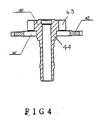
- the slip mechanism of Figure 4 is constructed to include an axle or centre wheel shaft 40 having an integral pinion 43 and made of a metallic material; a ring 41 made of a metallic material, the ring 41 being mounted on and drivingly engaging a portion 44 of the shaft 40, the portion 44 being spaced from the pinion 43; and a toothed wheel 42 made of a synthetic resin and frictionally engaging the ring 41 so as to be adapted to rotate the latter in a slipping manner.
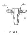
- the slip mechanism of Figure 5 is constructed to include: a shaft 52 and integral pinion made of a first synthetic resin; and a toothed wheel 51 made of a second synthetic resin different from that of the pinion 50 and frictionally engaging the pinion 50 so as to be adapted to rotate the latter in a slipping manner.
- a slip mechanism for use in a timepiece comprising a shaft member made of metallic material; a pinion which is fixed to a first portion of the shaft member; and a toothed wheel made of synthetic resin material, the toothed wheel being drivingly connected to a second portion of the shaft member so as to permit rotation of the toothed wheel to be transmitted therefrom to the shaft member and also to permit slip to occur therebetween characterised in that the pinion is made of synthetic resin material and that the second portion of the shaft member is an integral portion thereof which frictionally engages the toothed wheel.
- the pinion and/or the toothed wheel has been moulded onto the shaft member.
- the pinion and the toothed wheel are made of the same synthetic resin material.
- the shaft member and the pinion preferably have inter-engaging surfaces which prevent relative rotation therebetween.
- the shaft member may have an undercut portion within which a part of the pinion is located.
- the slip mechanism is incorporated in a minute wheel of a timepiece.
- FIG. 1 there is shown part of a timepiece comprising a timepiece frame 1 and a bridge 5.
- a minute wheel or centre wheel-and-pinion 2 which comprises an axle or shaft 20 having a ring or flange 20-a, a toothed wheel 21 and a pinion 22.
- the minute wheel 2 forms part of a wheel train comprising a third wheel 3 and a seconds or fourth wheel 4.
- a stem 6 which can be actuated from the outside; a clutch wheel 7 secured to the stem 6; a time correction wheel 8; a setting wheel 9; and an hour wheel or calendar hour wheel 10.
- the clutch wheel 7 When the stem 6 is actuated manually in an axial direction for correcting the time, the clutch wheel 7 is moved forward to the position, as indicated by broken lines, in which it comes into meshing engagement with the setting wheel 9 so that rotation of the stem 6 can be transmitted to the time correction wheel 8.
- the rotations of the clutch wheel 7 are transmitted through the setting wheel 9 and the time correction wheel 8 to the centre wheel-and-pinion 2 and to the hour wheel 10, thereby to correct the time. Since a slippage is then caused at the centre wheel-and-pinion or minute wheel 2 between the flange 20-a and the wheel 21, the time is corrected with the third wheel 3 and the fourth wheel, i.e. the seconds wheel, 4 being fixed.
- the centre wheel shaft or axle 20 is made of a metallic material and has a guide or bevelled portion 20-f for mounting a timepiece hand (not shown) into position, the shaft 20 also having integral rings 20-a and 20-b for holding a centre or toothed wheel 21 and a centre wheel pinion 22 respectively, as will be described hereinafter.
- the ring 20-b for guiding and holding the centre wheel pinion 22 is formed with an undercut portion 20-d for receiving a part 24 of the centre wheel pinion 22.
- the shaft 20 and pinion 22 have inter-engaging flat surfaces 20-e, 23 to prevent relative rotation therebetween.
- the centre wheel 21 and the centre wheel pinion 22 are formed by insert-moulding them onto the centre wheel shaft 20.
- the centre wheel shaft 20 may be positioned in an insert-mould so that the centre wheel 21 and the centre wheel pinion 22 can be injection-moulded simultaneously thereonto.
- the centre wheel 21 is shrunk onto the ring 20-a of the centre wheel shaft 20 so as to frictionally engage the latter in such a way that drive can be transmitted from the toothed wheel 21 to the shaft 20 while permitting slip to occur therebetween.
- the slip torque is determined by the fastening force resulting from the moulding shrinkage of the centre wheel 21 on the centre wheel shaft 20, i.e. the co-efficient of friction between the plastics material of the centre wheel 21 and the engagement portion of the ring 20-a of the metallic shaft 20.
- the slip torque of the centre wheel 21 can be stabilised at a low value either by improving the surface state of the engagement portion of the ring 20-a of the centre wheel shaft 20 by a polishing-finish or a barrelling-polish, or by providing effective lubrication of the engagement portion of the ring 20-a of the centre wheel shaft 20, e.g. by means of a fluoro-resin thin film such as Teflon (Registered Trade Mark).
- the shaft 20 is formed with the undercut and side surface portions 20-d, 20-e at the pinion mounting portion of the shaft, relative movement therebetween will not occur.
- the slip torque mentioned above can be better stabilised either by using an oil impregnated plastics material or by impregnating oil into the engagement face of the centre wheel 21 by annealing the latter in the oil.
- the wheels concerned with the time correction such as the clutch wheel 7, the setting wheel 9, the time correction wheel 8 and the third wheel 3 can be made of a softer material so as to reduce the cost of the timepiece drastically.
- the centre wheel shaft 20 with the pinion 22 can be machined by a general purpose automatic machine whereas these parts have had to be machined in the prior art by a special automatic machine.
- the centre wheel 21 and the pinion 22 can be simultaneously moulded unlike the separate parts of the prior art, the step of press fitting the ring 41 on the centre wheel shaft 40 of the prior art can be avoided so as to simplify the production process.
- the centre wheel-and-pinion 2 according to the present invention compares favourably, in quality and production cost, with many types of the prior art.
Landscapes
- Physics & Mathematics (AREA)
- General Physics & Mathematics (AREA)
- Gears, Cams (AREA)
- Electromechanical Clocks (AREA)
Applications Claiming Priority (2)
| Application Number | Priority Date | Filing Date | Title |
|---|---|---|---|
| JP14843988 | 1988-11-15 | ||
| JP148439/88U | 1988-11-15 |
Publications (2)
| Publication Number | Publication Date |
|---|---|
| EP0369704A2 true EP0369704A2 (fr) | 1990-05-23 |
| EP0369704A3 EP0369704A3 (fr) | 1991-02-06 |
Family
ID=31694886
Family Applications (1)
| Application Number | Title | Priority Date | Filing Date |
|---|---|---|---|
| EP19890311708 Withdrawn EP0369704A3 (fr) | 1988-11-15 | 1989-11-13 | Dispositif d'accouplement à friction pour pièces d'horlogerie |
Country Status (1)
| Country | Link |
|---|---|
| EP (1) | EP0369704A3 (fr) |
Cited By (2)
| Publication number | Priority date | Publication date | Assignee | Title |
|---|---|---|---|---|
| FR2690256A1 (fr) * | 1992-04-20 | 1993-10-22 | Timex Corp | Ensemble réducteur à accouplement pour montre. |
| EP2605080A1 (fr) * | 2011-12-16 | 2013-06-19 | ETA SA Manufacture Horlogère Suisse | Roue d'horlogerie surmoulée |
Family Cites Families (2)
| Publication number | Priority date | Publication date | Assignee | Title |
|---|---|---|---|---|
| DE3034135A1 (de) * | 1980-09-11 | 1982-03-18 | Werner 7744 Königsfeld Roth | Friktionsverbindung |
| US4785434A (en) * | 1986-11-19 | 1988-11-15 | Casio Computer Co., Ltd. | Slip structure of a timepiece |
-
1989
- 1989-11-13 EP EP19890311708 patent/EP0369704A3/fr not_active Withdrawn
Cited By (7)
| Publication number | Priority date | Publication date | Assignee | Title |
|---|---|---|---|---|
| FR2690256A1 (fr) * | 1992-04-20 | 1993-10-22 | Timex Corp | Ensemble réducteur à accouplement pour montre. |
| GB2266358A (en) * | 1992-04-20 | 1993-10-27 | Timex Corp | Slip coupling for use in a timepiece |
| EP2605080A1 (fr) * | 2011-12-16 | 2013-06-19 | ETA SA Manufacture Horlogère Suisse | Roue d'horlogerie surmoulée |
| WO2013087398A1 (fr) | 2011-12-16 | 2013-06-20 | Eta Sa Manufacture Horlogere Suisse | Roue d'horlogerie surmoulee |
| CN103998996A (zh) * | 2011-12-16 | 2014-08-20 | Eta瑞士钟表制造股份有限公司 | 包覆成型的钟表轮 |
| JP2015505962A (ja) * | 2011-12-16 | 2015-02-26 | ウーテーアー・エス・アー・マニファクチュール・オロロジェール・スイス | オーバモールド成形された時計用ホイール |
| US9323221B2 (en) | 2011-12-16 | 2016-04-26 | Eta Sa Manufacture Horlogere Suisse | Overmoulded timepiece wheel |
Also Published As
| Publication number | Publication date |
|---|---|
| EP0369704A3 (fr) | 1991-02-06 |
Similar Documents
| Publication | Publication Date | Title |
|---|---|---|
| EP0834786B1 (fr) | Montre avec dispositif de quantième | |
| EP0838736B1 (fr) | Train d'engrenage pour montre électronique | |
| US4785434A (en) | Slip structure of a timepiece | |
| US20210041835A1 (en) | Variation reduction mechanism of stop position of pointer | |
| EP0286078A2 (fr) | Mécanisme pour mise à l'heure pour pièce d'horlogerie analogique | |
| US5083300A (en) | Setting mechanism for a timepiece | |
| US20070012134A1 (en) | Defect-compensating gear assembly for a timepiece mechanism | |
| US4858210A (en) | Apparatus with synthetic resin hand shaft | |
| US7448415B2 (en) | Cam motion machine, method of assembly of such a machine and weaving loom in which such a machine is installed | |
| JP2759109B2 (ja) | 合成樹脂製の時計用二番車 | |
| US5217152A (en) | Gear mechanism and record medium feeding apparatus employing the same | |
| KR930007402B1 (ko) | 시계용 슬립 장치 | |
| JPH0320587Y2 (fr) | ||
| GB2197732A (en) | Apparatus with synthetic resin hand shaft | |
| EP1852753A1 (fr) | Horloge de type a indication par pointeur | |
| JP3104373B2 (ja) | 時計の歯車スリップ機構 | |
| JPS5841512Y2 (ja) | 歯車装置 | |
| JPH05196747A (ja) | 時計の二番車 | |
| JPH0535346Y2 (fr) | ||
| JPH0710315Y2 (ja) | 腕時計のカレンダー早修正構造 | |
| JPS641658Y2 (fr) | ||
| JPH05223954A (ja) | 時計の輪列車 | |
| US6086259A (en) | Change bearing for rollers | |
| JPS637906Y2 (fr) | ||
| JPH0587338U (ja) | 回転止め機構 |
Legal Events
| Date | Code | Title | Description |
|---|---|---|---|
| PUAI | Public reference made under article 153(3) epc to a published international application that has entered the european phase |
Free format text: ORIGINAL CODE: 0009012 |
|
| AK | Designated contracting states |
Kind code of ref document: A2 Designated state(s): CH DE FR GB LI |
|
| PUAL | Search report despatched |
Free format text: ORIGINAL CODE: 0009013 |
|
| AK | Designated contracting states |
Kind code of ref document: A3 Designated state(s): CH DE FR GB LI |
|
| RAP1 | Party data changed (applicant data changed or rights of an application transferred) |
Owner name: SEIKO EPSON CORPORATION |
|
| STAA | Information on the status of an ep patent application or granted ep patent |
Free format text: STATUS: THE APPLICATION IS DEEMED TO BE WITHDRAWN |
|
| 18D | Application deemed to be withdrawn |
Effective date: 19910907 |