EP0369824A2 - Appareil de lecture d'images - Google Patents
Appareil de lecture d'images Download PDFInfo
- Publication number
- EP0369824A2 EP0369824A2 EP89311960A EP89311960A EP0369824A2 EP 0369824 A2 EP0369824 A2 EP 0369824A2 EP 89311960 A EP89311960 A EP 89311960A EP 89311960 A EP89311960 A EP 89311960A EP 0369824 A2 EP0369824 A2 EP 0369824A2
- Authority
- EP
- European Patent Office
- Prior art keywords
- image
- scanning
- data
- image data
- image reading
- Prior art date
- Legal status (The legal status is an assumption and is not a legal conclusion. Google has not performed a legal analysis and makes no representation as to the accuracy of the status listed.)
- Withdrawn
Links
Images

Classifications
-
- H—ELECTRICITY
- H04—ELECTRIC COMMUNICATION TECHNIQUE
- H04N—PICTORIAL COMMUNICATION, e.g. TELEVISION
- H04N1/00—Scanning, transmission or reproduction of documents or the like, e.g. facsimile transmission; Details thereof
- H04N1/04—Scanning arrangements, i.e. arrangements for the displacement of active reading or reproducing elements relative to the original or reproducing medium, or vice versa
- H04N1/0402—Scanning different formats; Scanning with different densities of dots per unit length, e.g. different numbers of dots per inch (dpi); Conversion of scanning standards
- H04N1/0408—Different densities of dots per unit length
- H04N1/0411—Different densities of dots per unit length in the main scanning direction
-
- H—ELECTRICITY
- H04—ELECTRIC COMMUNICATION TECHNIQUE
- H04N—PICTORIAL COMMUNICATION, e.g. TELEVISION
- H04N1/00—Scanning, transmission or reproduction of documents or the like, e.g. facsimile transmission; Details thereof
- H04N1/04—Scanning arrangements, i.e. arrangements for the displacement of active reading or reproducing elements relative to the original or reproducing medium, or vice versa
- H04N1/0402—Scanning different formats; Scanning with different densities of dots per unit length, e.g. different numbers of dots per inch (dpi); Conversion of scanning standards
- H04N1/0417—Conversion of standards
-
- H—ELECTRICITY
- H04—ELECTRIC COMMUNICATION TECHNIQUE
- H04N—PICTORIAL COMMUNICATION, e.g. TELEVISION
- H04N1/00—Scanning, transmission or reproduction of documents or the like, e.g. facsimile transmission; Details thereof
- H04N1/04—Scanning arrangements, i.e. arrangements for the displacement of active reading or reproducing elements relative to the original or reproducing medium, or vice versa
- H04N1/0402—Scanning different formats; Scanning with different densities of dots per unit length, e.g. different numbers of dots per inch (dpi); Conversion of scanning standards
- H04N1/042—Details of the method used
- H04N1/0443—Varying the scanning velocity or position
-
- H—ELECTRICITY
- H04—ELECTRIC COMMUNICATION TECHNIQUE
- H04N—PICTORIAL COMMUNICATION, e.g. TELEVISION
- H04N1/00—Scanning, transmission or reproduction of documents or the like, e.g. facsimile transmission; Details thereof
- H04N1/40—Picture signal circuits
- H04N1/40068—Modification of image resolution, i.e. determining the values of picture elements at new relative positions
-
- H—ELECTRICITY
- H04—ELECTRIC COMMUNICATION TECHNIQUE
- H04N—PICTORIAL COMMUNICATION, e.g. TELEVISION
- H04N1/00—Scanning, transmission or reproduction of documents or the like, e.g. facsimile transmission; Details thereof
- H04N1/04—Scanning arrangements, i.e. arrangements for the displacement of active reading or reproducing elements relative to the original or reproducing medium, or vice versa
- H04N1/10—Scanning arrangements, i.e. arrangements for the displacement of active reading or reproducing elements relative to the original or reproducing medium, or vice versa using flat picture-bearing surfaces
- H04N1/1013—Scanning arrangements, i.e. arrangements for the displacement of active reading or reproducing elements relative to the original or reproducing medium, or vice versa using flat picture-bearing surfaces with sub-scanning by translatory movement of at least a part of the main-scanning components
Definitions
- the present invention relates generally to an image reading apparatus, and more particularly to an image reading apparatus which reads document images and provides data to other systems.
- a typical image reading apparatus has a structure as shown in Figure 1.
- the image reading apparatus has a body 11 and a cover 13.
- the body 11 houses many elements, such as optical members, mechanical elements and electrical circuits.
- the cover 13 covers a document exposure base 12 (see Figure 2) on the body 13.
- the document exposure base 12 is made of a light translucent material, e.g. glass.
- a document containing an image to be read is held between the document exposure base 12 and the cover 13.
- the body 11 is further provided with a control panel 14 on the front of the body 11 so that the control panel 14 is exposed.
- the image reading apparatus has a scanner 15.
- the scanner 15 is provided below the document exposure base 12, as shown in Figure 2.
- the scanner 15 moves along the document exposure base 12 and optically scans an image on a document D which is held between the document exposure base 12 and the cover 13.
- the scanner 15 has a light source 16, a focus lens 17, a photoelectric transducer 18 and a carriage 19.
- the light source 16 illuminates the document D.
- the focus lens 17 optically picks up the document images and focuses the images on the photoelectric transducer 18.
- the photoelectric transducer 18 generates electrical outputs in response to the document images.
- the photoelectric transducer 18 has a photo detector, for instance, a CCD (Charge Coupled Device) line sensor for reading the document images in a line along the CCD line sensor.
- the CCD line sensor of the photoelectric transducer 18 has a resolution of, for instance, 16 lines/mm for its longitudinal direction, or the direction perpendicular to the scanning direction of the scanner 15.
- the scanner 15 is driven by a scanner driving mechanism, as shown in Fig. 3.
- the scanner driving mechanism has a guide rail 21, a guide rod 22, a timing belt 25 and a pulse motor 26.
- the guide rail 21, the guide rod 22 and the timing belt 25 are disposed along the scanning direction.
- the carriage 19 is provided with a roller 20 at its one end.
- the roller 20 has been designed to travel on the guide rail 21.
- the guide rod 22 passes through the carriage 19.
- the carriage 19 is movable along the guide rail 21 and the guide rod 22.
- the carriage 19 is fixed to the timing belt 25.
- the timing belt 25 is suspended between two pulleys 23 and 24.
- One of the pulleys 23 and 24, e.g., the pulley 24, is coupled to the pulse motor 26.
- the scanner 15 is driven in the scanning direction by the pulse motor 26.
- Such an image reading apparatus is provided with a read region designator which designates a region of document images to be read.
- the read region designator consists of an electrical circuit (not shown).
- coordinate dimensions of the specified region are determined by manual operation of a keyboard on the control panel 14. Therefore, it can take some time to designate a specified region to be read. Further, if many regions of the document are to be read, the designating process becomes very complicated.
- all images on a document are first read and displayed on a display screen of a device, such as an image processor.
- a specified region of the image to be read is then designated by using a pointing device, e.g., a mouse.
- this type of image reading apparatus has a considerably high resolution, for instance, 4 lines/mm, 8 lines/mm or 16 lines/mm. If, for instance, the entire document image in an A3 size is read in three colors of R, G and B, 256 gradations and a resolution of 16 lines/mm the conventional image reading apparatus needs an image memory with a large volume, i.e., more than 95 M bytes (mega bytes). Further, the conventional image reading apparatus described above is slow in designating regions of document images to be read.
- the present invention therefore seeks to provide an image reading apparatus which is able to solve the above-described problems.
- the present invention also seeks to provide an image reading apparatus which is capable of reading and processing entire document images at high speed using a small capacity memory.
- An image reading apparatus includes a scanner for scanning the image and forming image data, a driver for driving the scanner, a data processor for processing the image data and supplying output information generated from the image data, a memory for storing the output information from the data processor and a controller for setting a high discard rate to be used by the data processor during a low resolution reading operation, in which a relatively high percentage of input information is automatically discarded.
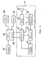
- the embodiment of the image reading apparatus 11 has a controller 31, a motor driver 32, a photoelectric transducer 18, a data processor 33, and output buffer memory 34 and a motor 26.
- the controller 31 controls the entire image reading apparatus.
- the controller 31 is coupled to the motor driver 32, the photoelectric transducer 18, the data processor 33 and the output buffer memory 34.
- the motor driver 32 controls the motor 26 which drives a scanner 15 (see Figures 2 and 3), which is provided with the photoelectric transducer 18.
- the data processor 33 processes an output signal from the photoelectric transducer 18 so that the line density of the output signal can be converted to another line density, for instance, 4 lines/mm, 8 lines/mm, or even 1 line/mm for low resolution image reading.
- a line-density conversion signal output from the data processor 33 is temporarily stored in the output buffer memory 34, which has a storage capacity of, for instance, about 400 k bytes.
- the controller 31 is also connected to a host computer 35 of an apparatus such as a personal computer or a work station. Such apparatus is provided with a memory 36. Further, the host computer 35 may be provided with a keyboard 37, an image display 38 and a mouse 39. The keyboard 37 is used for entering various data items. The image display 38 displays information or options which can be selected for example by using mouse 39 as a pointing device to select parts of the information, displayed on the image display 38. A command for directing a rough image reading operation, a reading at an ordinary density of 8 lines/mm or 16 lines/mm etc., may be output from the host computer 35 according to the operation of the keyboard 37.
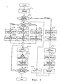
- a command is output from the host computer 35.
- This command is analyzed by the controller 31 in the image reading apparatus 11 (steps ST1 and ST2).
- a high scanning speed e.g., 1 mm/sec, which is the highest of the scanning speeds of the scanner 15, is set for the motor driver 32 (step ST3).
- a high discard rate e.g., "16" (in which only 1 data item out of every 16 is utilised) which is the highest discard rate among the discard rates of the data processor 33, is set into the data processor 33 (step ST4).
- the motor 26 is driven by the motor driver 32 at the speed set as described above, and the scanner 15 moves at the first scanning speed 1 mm/scan period, and images on the document D placed on the document exposure base 12 (see Fig 2) are read through the photoelectric transducer 18 (step ST5).
- the output of the photoelectric transducer 18 is supplied to the data processor 33, and the input data is selected out in response to the first discard rate "16".
- the volume of data is about 374 k bytes.
- Output data from the data processor 33 is then stored in the output buffer memory 34 (step ST6).
- step ST7 When all the data of the document images from the data processor 33 has been stored in the output buffer memory 34, this data is transferred to the memory 36 of the host computer 35 (step ST7).
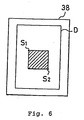
- the image data stored in the memory 36 is displayed on the image display 38, providing a low resolution image of the entire region of the document D is displayed on the image display 38, as shown in Figure 6.
- the low resolution image is then used to select a more distinct, i.e. higher resolution image reading of a limited region of the document D.
- two diagonal points S1 and S2 of a desired limited region image Ir of the document D, which is to be transferred to other apparatus, is designated by using the mouse 39 (step 5T8).
- a desired scanning speed for the distinct image reading is designated through the keyboard 37.
- the host computer 35 sets the region data corresponding to the diagonal points S2 and S2 and the designated scanning speed to the controller 31 of the image reading apparatus 11 in the controller 31 (step ST9).
- the controller 31 judges the designated scanning speed (step ST10).
- the process directly goes to the step ST10.
- step ST11a When a first distinct scanning speed has been set, the process goes to a step ST11a. When a second distinct scanning speed has been set, the process goes to a step ST11b. When a third distinct scanning speed has been set, the process goes to a step ST11c.
- step sT11a a low scanning speed, e.g. 0.0625 mm/scan period is set in the motor driver 32. Also, a high line-density conversion rate, e.g., 1" (1 to 1 data) is set into the data processor 33 (step ST12a).
- step ST11b an intermediate scanning speed, e.g., 0.125 mm/scan period is set in the motor driver 32.
- an intermediate line-density conversion rate e.g., "2" (1 per 2 data) is set into the data processor 33 (step ST12b).
- a high scanning speed e.g., 0.25 mm/scan period is set in the motor driver 32.
- a low line-density conversion rate e.g., "4" (1 per 4 data) is set into the data processor 33 (step ST12c). data processor 33 (step ST12c).
- step ST13 the limited region of the document image is read at the set scanning speed and the line-density conversion rate corresponding to the set scanning speed (step ST13).
- the data processor 33 supplies distinct image data ready by the photoelectric transducer 18 to the output buffer memory 34 (step ST14).
- the buffer memory 34 successively stores the distinct image data. If the output buffer memory 34 becomes full or the distinct image reading of the limited region has been completed, the scanning operation of the scanner 15 is interrupted and the data stored in the output buffer memory 34 are transferred to the memory 36 of the host computer 35 (step ST15). After step ST15, it is checked whether the distinct image reading of the limited region has been completed or not (step ST16). If the distinct image reading of the limited region has not been completed, the steps ST13 to ST16 are repeated until the distinct image reading of the limited region is completed. If the distinct image reading of the limited region has been completed, the process goes to END.
- a command for low resolution reading is first set so that the entire region of the document images is read at a high speed and signal processing is carried out at a higher discard rate than normal.
- signal processing is carried out at a higher discard rate than normal.
- the document scanning speed and the discard rate for the data processor 33 are set in the image reading apparatus 11 itself. This reduces the load on the host computer 35 in that the host computer 35 needs only to supply the required command. Therefore, they do not affect the construction of the host computer 35.
- the output buffer memory 14 is used for low resolution reading as well as ordinary scanning in this embodiment, but the invention is not limited to this, the output buffer memory 34 may be used only for low resolution scanning and the memory of the host computer 35 may be used for normal reading.
- an image reading apparatus which is capable of storing entire document images in a storage means of small capacity and shorten data processing time by operating the driving means at high speed, scanning and reading the entire document images by the scanning means at the high speed, processing the document images which are read by the scanning means through the signal processing means with a large thinning rate set and storing the selected data in the storage means.
- the present invention operates the driving means at high speed, scans and reads the entire document images at high speed, processes the document images thus read by the scanning means through the signal processing means for which a large thinning rate has been established, and stores them in the storage means, and is thus capable of storing the entire document images in a storage means of small capacity and, at the same time, makes it possible to reduce the data processing time.
Landscapes
- Engineering & Computer Science (AREA)
- Multimedia (AREA)
- Signal Processing (AREA)
- Facsimile Scanning Arrangements (AREA)
- Image Input (AREA)
- Editing Of Facsimile Originals (AREA)
Applications Claiming Priority (2)
| Application Number | Priority Date | Filing Date | Title |
|---|---|---|---|
| JP63290150A JP2902655B2 (ja) | 1988-11-18 | 1988-11-18 | 画像読取装置及び画像読取方法 |
| JP290150/88 | 1988-11-18 |
Publications (2)
| Publication Number | Publication Date |
|---|---|
| EP0369824A2 true EP0369824A2 (fr) | 1990-05-23 |
| EP0369824A3 EP0369824A3 (fr) | 1991-12-11 |
Family
ID=17752425
Family Applications (1)
| Application Number | Title | Priority Date | Filing Date |
|---|---|---|---|
| EP19890311960 Withdrawn EP0369824A3 (fr) | 1988-11-18 | 1989-11-17 | Appareil de lecture d'images |
Country Status (3)
| Country | Link |
|---|---|
| US (1) | US5128777A (fr) |
| EP (1) | EP0369824A3 (fr) |
| JP (1) | JP2902655B2 (fr) |
Cited By (3)
| Publication number | Priority date | Publication date | Assignee | Title |
|---|---|---|---|---|
| EP0488974A3 (en) * | 1990-11-27 | 1992-09-09 | Knut Christian Achates Scherman | A method for imaging an object and a system for carrying out the method |
| EP0617540A3 (fr) * | 1993-03-25 | 1994-10-26 | Hewlett Packard Co | Méthode et appareil de balayage à vitesse variable limitée. |
| EP0851658A3 (fr) * | 1996-12-27 | 2000-05-10 | Hewlett-Packard Company | Balayeur d'image avec vitesse et rapport signal-sur-bruit variable qui dépendent de la définition de balayage demandée et du type de données demandé |
Families Citing this family (5)
| Publication number | Priority date | Publication date | Assignee | Title |
|---|---|---|---|---|
| JP2771712B2 (ja) * | 1991-06-10 | 1998-07-02 | キヤノン株式会社 | 画素密度変換装置 |
| US5301244A (en) * | 1991-07-18 | 1994-04-05 | Eastman Kodak Company | Computer input scanner incorporating multiple scanning modes |
| US5818612A (en) * | 1994-11-29 | 1998-10-06 | Nec Corporation | Scanning method and apparatus for pre-scanning document to allow manual adjustment of its orientation |
| DE69620533T2 (de) * | 1995-10-04 | 2002-10-02 | Canon K.K., Tokio/Tokyo | Bildverarbeitungsverfahren |
| KR100234432B1 (ko) | 1997-05-08 | 1999-12-15 | 윤종용 | 셔틀 방식 스캔 장치의 프리 스캔 방법 |
Family Cites Families (12)
| Publication number | Priority date | Publication date | Assignee | Title |
|---|---|---|---|---|
| JPS5222494B2 (fr) * | 1972-12-15 | 1977-06-17 | ||
| US3912861A (en) * | 1974-01-30 | 1975-10-14 | Exxon Research Engineering Co | Method and apparatus for time compression of facsimile transmissions |
| JPS5540460A (en) * | 1978-09-14 | 1980-03-21 | Fuji Xerox Co Ltd | Image transfer device |
| GB2030823B (en) * | 1978-10-02 | 1982-11-03 | Ibm | Image data manipulation apparatus |
| US4447830A (en) * | 1981-09-10 | 1984-05-08 | Xerox Corporation | Image scanning apparatus and method |
| JPS58108885A (ja) * | 1981-12-23 | 1983-06-29 | Nippon Kogaku Kk <Nikon> | 静止画像信号変換装置 |
| US4691238A (en) * | 1982-10-21 | 1987-09-01 | Dainippon Screen Mfg. Co., Ltd. | Method and apparatus of storing image data into a memory in a layout scanner system |
| JPS60130262A (ja) * | 1983-12-16 | 1985-07-11 | Fujitsu Ltd | 原稿の部分電送方法 |
| US4656524A (en) * | 1985-12-23 | 1987-04-07 | Polaroid Corporation | Electronic imaging copier |
| US4862283A (en) * | 1987-11-02 | 1989-08-29 | Eastman Kodak Company | Image discrimination with continuous tone area thinning |
| DE3841639A1 (de) * | 1988-06-13 | 1989-12-14 | Luk Lamellen & Kupplungsbau | Einrichtung zum daempfen von schwingungen |
| JPH06173471A (ja) * | 1992-12-02 | 1994-06-21 | Toagosei Chem Ind Co Ltd | きしみ又は床鳴り防止方法 |
-
1988
- 1988-11-18 JP JP63290150A patent/JP2902655B2/ja not_active Expired - Lifetime
-
1989
- 1989-11-17 EP EP19890311960 patent/EP0369824A3/fr not_active Withdrawn
- 1989-11-17 US US07/437,893 patent/US5128777A/en not_active Expired - Lifetime
Cited By (3)
| Publication number | Priority date | Publication date | Assignee | Title |
|---|---|---|---|---|
| EP0488974A3 (en) * | 1990-11-27 | 1992-09-09 | Knut Christian Achates Scherman | A method for imaging an object and a system for carrying out the method |
| EP0617540A3 (fr) * | 1993-03-25 | 1994-10-26 | Hewlett Packard Co | Méthode et appareil de balayage à vitesse variable limitée. |
| EP0851658A3 (fr) * | 1996-12-27 | 2000-05-10 | Hewlett-Packard Company | Balayeur d'image avec vitesse et rapport signal-sur-bruit variable qui dépendent de la définition de balayage demandée et du type de données demandé |
Also Published As
| Publication number | Publication date |
|---|---|
| US5128777A (en) | 1992-07-07 |
| JP2902655B2 (ja) | 1999-06-07 |
| EP0369824A3 (fr) | 1991-12-11 |
| JPH02137472A (ja) | 1990-05-25 |
Similar Documents
| Publication | Publication Date | Title |
|---|---|---|
| US5047871A (en) | Direction scaling method and apparatus for image scanning resolution control | |
| US7292378B2 (en) | Image reader | |
| US5416609A (en) | Image pickup apparatus for focusing an object image based on mirror reflected height of the object | |
| EP0369824A2 (fr) | Appareil de lecture d'images | |
| US4803561A (en) | Image reading method and apparatus | |
| US7554704B2 (en) | Image scanning apparatus having a scanning position adjustment capability | |
| JPH05145715A (ja) | イメージ入力スキヤナ | |
| US6271912B1 (en) | Film scanning device | |
| KR100409143B1 (ko) | 화상판독장치및판독방법 | |
| EP0182398B1 (fr) | Appareil et méthode de balayage de documents | |
| US5690406A (en) | Control method for microfilm image reader | |
| JPH06233069A (ja) | 画像デジタル化装置およびそのデジタル化法 | |
| US4755882A (en) | Electronic blackboard capable of providing hardcopy | |
| US6256056B1 (en) | Image input apparatus which controls charge accumulation of line sensor in association with intermittent scan motion of scanning means | |
| US6594038B1 (en) | Image reading apparatus and processing method of an image signal | |
| US6341010B1 (en) | Film scanner | |
| KR100271816B1 (ko) | 화상입력장치 | |
| JP2585289B2 (ja) | 読取装置 | |
| GB2236448B (en) | Image scanning apparatus | |
| JPH0594557A (ja) | バ−コ−ド読取り装置 | |
| JPH0681217B2 (ja) | 画像読取装置 | |
| JPH02184166A (ja) | 読取装置 | |
| JPH0637972A (ja) | 画像読み取り装置 | |
| JPS6319964A (ja) | 原稿読取装置 | |
| JPS60251472A (ja) | 画像読取り装置 |
Legal Events
| Date | Code | Title | Description |
|---|---|---|---|
| PUAI | Public reference made under article 153(3) epc to a published international application that has entered the european phase |
Free format text: ORIGINAL CODE: 0009012 |
|
| 17P | Request for examination filed |
Effective date: 19891208 |
|
| AK | Designated contracting states |
Kind code of ref document: A2 Designated state(s): DE FR GB |
|
| PUAL | Search report despatched |
Free format text: ORIGINAL CODE: 0009013 |
|
| AK | Designated contracting states |
Kind code of ref document: A3 Designated state(s): DE FR GB |
|
| 17Q | First examination report despatched |
Effective date: 19931019 |
|
| STAA | Information on the status of an ep patent application or granted ep patent |
Free format text: STATUS: THE APPLICATION IS DEEMED TO BE WITHDRAWN |
|
| 18D | Application deemed to be withdrawn |
Effective date: 19950204 |