EP0369838B1 - Verfahren und Vorrichtung zum Ordnen von Flaschen in vertikaler Lage - Google Patents
Verfahren und Vorrichtung zum Ordnen von Flaschen in vertikaler Lage Download PDFInfo
- Publication number
- EP0369838B1 EP0369838B1 EP89402880A EP89402880A EP0369838B1 EP 0369838 B1 EP0369838 B1 EP 0369838B1 EP 89402880 A EP89402880 A EP 89402880A EP 89402880 A EP89402880 A EP 89402880A EP 0369838 B1 EP0369838 B1 EP 0369838B1
- Authority
- EP
- European Patent Office
- Prior art keywords
- bottles
- beams
- support
- batch
- jack
- Prior art date
- Legal status (The legal status is an assumption and is not a legal conclusion. Google has not performed a legal analysis and makes no representation as to the accuracy of the status listed.)
- Expired - Lifetime
Links
- 238000000034 method Methods 0.000 title claims abstract description 20
- 210000003739 neck Anatomy 0.000 claims description 13
- 230000033001 locomotion Effects 0.000 claims description 7
- 230000008569 process Effects 0.000 claims description 5
- 238000004806 packaging method and process Methods 0.000 claims description 4
- 238000000151 deposition Methods 0.000 claims description 3
- 230000005540 biological transmission Effects 0.000 claims 2
- 238000005070 sampling Methods 0.000 description 10
- 239000006185 dispersion Substances 0.000 description 5
- 230000008520 organization Effects 0.000 description 5
- 241000722921 Tulipa gesneriana Species 0.000 description 4
- 230000000694 effects Effects 0.000 description 4
- 238000010586 diagram Methods 0.000 description 3
- 238000009434 installation Methods 0.000 description 3
- 230000006978 adaptation Effects 0.000 description 2
- 230000007257 malfunction Effects 0.000 description 2
- 230000007246 mechanism Effects 0.000 description 2
- 230000007935 neutral effect Effects 0.000 description 2
- 230000003042 antagnostic effect Effects 0.000 description 1
- 230000000903 blocking effect Effects 0.000 description 1
- 235000019993 champagne Nutrition 0.000 description 1
- 238000010276 construction Methods 0.000 description 1
- 231100001261 hazardous Toxicity 0.000 description 1
- 238000009830 intercalation Methods 0.000 description 1
- 230000002687 intercalation Effects 0.000 description 1
- 238000002955 isolation Methods 0.000 description 1
- 238000004519 manufacturing process Methods 0.000 description 1
- 230000004048 modification Effects 0.000 description 1
- 238000012986 modification Methods 0.000 description 1
- 230000009467 reduction Effects 0.000 description 1
- 230000008521 reorganization Effects 0.000 description 1
- 230000000717 retained effect Effects 0.000 description 1
- 230000002441 reversible effect Effects 0.000 description 1
- 238000012163 sequencing technique Methods 0.000 description 1
- 125000006850 spacer group Chemical group 0.000 description 1
- 230000002269 spontaneous effect Effects 0.000 description 1
- 230000007704 transition Effects 0.000 description 1
- 235000014101 wine Nutrition 0.000 description 1
Images



Classifications
-
- B—PERFORMING OPERATIONS; TRANSPORTING
- B65—CONVEYING; PACKING; STORING; HANDLING THIN OR FILAMENTARY MATERIAL
- B65B—MACHINES, APPARATUS OR DEVICES FOR, OR METHODS OF, PACKAGING ARTICLES OR MATERIALS; UNPACKING
- B65B21/00—Packaging or unpacking of bottles
- B65B21/02—Packaging or unpacking of bottles in or from preformed containers, e.g. crates
- B65B21/14—Introducing or removing groups of bottles, for filling or emptying containers in one operation
- B65B21/18—Introducing or removing groups of bottles, for filling or emptying containers in one operation using grippers engaging bottles, e.g. bottle necks
- B65B21/20—Introducing or removing groups of bottles, for filling or emptying containers in one operation using grippers engaging bottles, e.g. bottle necks with means for varying spacing of bottles
Definitions
- the present invention relates to a method and a device for packaging bottles in a vertical position.
- the lot withdrawn necessarily comprises an odd number of rows so that, when two beds are superposed, the bottles of the upper bed are placed between the necks of the lower bed, a sampling of lots comprising an even number of rows would require adjusting the transfer movement of each bed, which is not possible in a simple way for a robot arm.
- the robot arm which collects, transfers and stacks the beds, comprises grippers which are in the form of a sleeve which covers each neck of the bottle of the batch in question. These sleeves are pneumatically tightened on the necks for transporting the bottles.
- the mounting of each gripper on the robot arm is flexible and tolerates an inaccuracy in the position of the bottle of a few millimeters, which determines the limits of adaptation of the system.
- the sequencing of the bottles does not always operate in a perfect manner.
- hazards due to spontaneous jamming (bracing between bottles) or especially to friction between bottles and along the edges of the conveyor which are essentially variable, in particular due to the presence of labels on the bottle.
- the location of the last bottles of the batch depends on the dispersion of the sides in the stack of, for example, eleven rows of bottles, dispersion depending on the manufacturing tolerances of the bottles, the presence of foreign bodies between the bottles (labels peeled off, crumpled and inserted in the batch ).
- the invention intends to remedy these drawbacks by proposing a method and a machine which take into account size dispersions, which reduce the risks of blocking or jamming of the bottles during their conveying, and which include means for easily adapting to the different types of bottles encountered.
- This method also includes a step of transferring the bottles between the sampling step and the depositing step during which the rotation and approximation steps are carried out.
- the second object of the invention is a device for implementing the above method comprising a plurality of gripping members carried by the end of an arm movable horizontally and vertically between a sampling station and an unloading station on a base or intermediate support for the bottles of each batch, in which the arm is provided with a support fixed relative to the arm, the support carrying several beams which extend transversely to the lines of bottles when the support is above of the sampling station and which can slide parallel to themselves on guides carried by the support, each beam comprising a plurality of plates mounted to rotate in the beam around vertical axes spaced from each other by a distance equal to that separating the axes of the rows of bottles, each plate comprising a pair of gripping members arranged symmetrically with respect to one another the corresponding axis of rotation.
- a drive member is coupled to the beams to move them between a first position where they are spaced from each other and a second position where they are brought together.
- this motor member comprises a jack coupled between the two end beams and members for transmitting the movement of the end beams to the intermediate beams, which constitute the beam spacer member between them in each of the two positions.
- the plates carried by a beam are connected by an eccentric finger to a common rod for operating their rotation coupled to a control jack by a driving cleat and the common rod is coupled to a set of two antagonistic springs, which maintains it, in the absence of effort from the jack, in a middle position corresponding to an alignment of the grippers perpendicular to the parts.
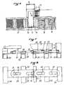
- FIG. 1 represents, seen from above, the end of a horizontal conveyor 1, having a final stop 2 on which, in the direction A of advancement of the conveyor, the bottles 3 come to stop.
- the bottles 3 are guided in corridors 4 whose edges 5 are sufficiently wide (or in two parts with adjustable spacing) so that the axes of these corridors are distant from each other by a value e substantially equal to ⁇ 2 times the diameter d of the bottle.
- the bottles therefore form parallel rows of contiguous bottles.
- the batch of bottles to be sampled consists of a plurality of rows R1, R2 Vietnamese bottles, one row consisting of bottles of the same level in each row. Once this sample has been taken, we go to the process step of printing a rotation on the bottles to obtain the organization shown in FIG. 2.
- the third step of the method according to the invention then consists in bringing the pairs of nested rows together in order to obtain the organization of FIG. 3.
- FIG. 3 is a diagram seen from above of the first bed made.
- the risks of poor grip are very significantly reduced for several reasons.
- the bottles are picked while they are online. Their installation in line is much less hazardous than the natural staggered arrangement, because it is done in corridors where only one bottle can engage.
- the dispersion of dimensions (diameter of the bottles) only has an effect in one direction: the axis of the queue, while for the sampling of bottles already staggered, the dispersion of dimensions is multidirectional in the plan.
- the effects of cumulation in all these directions can lead to a greater overall offset than the online offset of the last bottle in the batch relative to the gripper.
- the latter also has by construction sufficient flexibility to absorb this offset.
- the result of this mechanization of staggered bottles is a very significant reduction in the risks of machine malfunction putting implement the process.
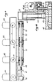
- Figure 4 illustrates a schematic top view of such a machine which is very similar in its general architecture to known machines.
- This figure shows the horizontal conveyor 1 for feeding and aligning the bottles at the sampling station 10.
- the bottles accumulate there in file against the stopper 2.
- a transfer arm 11 is mounted rotating around an axis vertical 12 on a base 13 and carries at its free end a device 14 provided with grippers at its lower part whose gripping function of the necks of the bottles is provided by known means of pneumatic annular bladder type.
- the arm 11 therefore makes it possible to transfer a batch of bottles from station 10 to loading station 15 (located in the figure under the equipment 14), to which, by conveyor means, reach pallets 16 and from which, by this same conveyor or another, are removed from the loaded pallets 17.
- the equipment 14 has vertical mobility with respect to the arm 11 for lifting the sampled bottles and depositing them at different levels depending on whether or not the pallet carries one or more beds of lower bottles.
- the equipment 14 comprises a horizontal fixed structure 20 which is integral with the end of the arm 11.
- This structure 20 carries beneath its underside fixed guide bars 21 on which beams 22 can slide (by means of bearings 23). These beams are therefore transverse to the sliding bars 21.
- Two end beams 24 and 25, parallel to the other beams 22, are integral with rods 26, 27 which slide in fixed bearings 28, 29 integral with the structure 20. This arrangement allows the length of the bars to guidance to be as short as possible, that is to say of length substantially equal to that of all the beams in the tightened position against each other.
- FIGS 7 and 8 there is shown in isolation the connection of the beams 22, 24 and 25 between them and to an actuating cylinder 30.
- This cylinder is coupled between the centers of the two end beams 24, 25.
- Each of these beams carries a vertical finger 31 which is housed in an oblong slot 32 of a plate 33 secured to the beam 22 which is adjacent to it and which is directed towards the corresponding end beam.
- This plate 33 is extended on the other side of each beam 22 by a symmetrical part of the previous one with an identical light 32 to receive a vertical finger 31 which is integral with each next beam 22.
- each beam 22, 24 or 25 is equipped with a plurality lity of lower plates 40, rotatably mounted in the beam around the vertical axes 41, spaced from each other by the distance e separating the rows of bottles, and equipped on their underside with two pneumatic tulip-shaped grippers 42 l one from the other with respect to the axis of rotation 41.
- the tulips are shown aligned from one beam to the other, the lower plates 40 having their axis perpendicular to that of the beam (see Figure 9).
- the plates are at an angle, at 45 ° to the beam.
- the simultaneous rotation of the plates of each beam is obtained by a finger 43, eccentric relative to the axis 41 and carrying a rotating ring 44 on which is fixed a tangent rod 45 for connecting the fingers of the plates carried by the same beam.
- This rod 45 carries in the middle part a fixed jumper which overlaps a cleat 47 for driving with a possibility of sliding between them in a direction perpendicular to the rod.
- This cleat 47 is, in the device shown, located above the rod 45 and is integral with a rod 48 of cylinder 49, with double effect.
- This cylinder rod 48 is associated - see FIG.
- the apparatus described with reference to FIGS. 4 to 10 makes it possible to implement the method of the invention and to adapt this implementation to the main types of bottles encountered. It also allows, thanks to the adjustment possibilities it offers, to form beds of contiguous or spaced bottles and thus respond to all requests. Finally, it allows the reorganization of the bottle lot sampled during its transfer from the sampling station to the loading station.
Landscapes
- Engineering & Computer Science (AREA)
- Mechanical Engineering (AREA)
- Wrapping Of Specific Fragile Articles (AREA)
- Attitude Control For Articles On Conveyors (AREA)
- Specific Conveyance Elements (AREA)
- Warehouses Or Storage Devices (AREA)
Claims (10)
Priority Applications (1)
| Application Number | Priority Date | Filing Date | Title |
|---|---|---|---|
| AT89402880T ATE71593T1 (de) | 1988-10-28 | 1989-10-18 | Verfahren und vorrichtung zum ordnen von flaschen in vertikaler lage. |
Applications Claiming Priority (2)
| Application Number | Priority Date | Filing Date | Title |
|---|---|---|---|
| FR8814151 | 1988-10-28 | ||
| FR8814151A FR2638421B1 (fr) | 1988-10-28 | 1988-10-28 | Procede et dispositif de conditionnement de bouteilles en position verticale |
Publications (2)
| Publication Number | Publication Date |
|---|---|
| EP0369838A1 EP0369838A1 (de) | 1990-05-23 |
| EP0369838B1 true EP0369838B1 (de) | 1992-01-15 |
Family
ID=9371405
Family Applications (1)
| Application Number | Title | Priority Date | Filing Date |
|---|---|---|---|
| EP89402880A Expired - Lifetime EP0369838B1 (de) | 1988-10-28 | 1989-10-18 | Verfahren und Vorrichtung zum Ordnen von Flaschen in vertikaler Lage |
Country Status (5)
| Country | Link |
|---|---|
| EP (1) | EP0369838B1 (de) |
| AT (1) | ATE71593T1 (de) |
| DE (1) | DE68900719D1 (de) |
| ES (1) | ES2030290T3 (de) |
| FR (1) | FR2638421B1 (de) |
Families Citing this family (2)
| Publication number | Priority date | Publication date | Assignee | Title |
|---|---|---|---|---|
| US9073222B2 (en) | 2013-11-14 | 2015-07-07 | Propack Processing and Packaging Systems, Inc. | End effector |
| IT202000016630A1 (it) * | 2020-07-09 | 2022-01-09 | Gd Spa | Dispositivo di trasferimento, particolarmente per una macchina confezionatrice |
Family Cites Families (2)
| Publication number | Priority date | Publication date | Assignee | Title |
|---|---|---|---|---|
| GB999282A (en) * | 1963-02-09 | 1965-07-21 | Dawson Bros Ltd | Improvements relating to machines for loading bottles into cartons, boxes or the like |
| DE1240462B (de) * | 1965-01-20 | 1967-05-11 | Enzinger Union Werke Ag | Verfahren und Vorrichtung zum gleichzeitigen buendelweisen Um- und Einsetzen von in zur Anfoerderrichtung parallelen Reihen aufgestauten Flaschen u. dgl. in Kaesten, Kisten, Harasse u. dgl. |
-
1988
- 1988-10-28 FR FR8814151A patent/FR2638421B1/fr not_active Expired - Fee Related
-
1989
- 1989-10-18 EP EP89402880A patent/EP0369838B1/de not_active Expired - Lifetime
- 1989-10-18 DE DE8989402880T patent/DE68900719D1/de not_active Expired - Fee Related
- 1989-10-18 ES ES198989402880T patent/ES2030290T3/es not_active Expired - Lifetime
- 1989-10-18 AT AT89402880T patent/ATE71593T1/de not_active IP Right Cessation
Also Published As
| Publication number | Publication date |
|---|---|
| FR2638421B1 (fr) | 1991-01-11 |
| FR2638421A1 (fr) | 1990-05-04 |
| DE68900719D1 (de) | 1992-02-27 |
| ATE71593T1 (de) | 1992-02-15 |
| EP0369838A1 (de) | 1990-05-23 |
| ES2030290T3 (es) | 1992-10-16 |
Similar Documents
| Publication | Publication Date | Title |
|---|---|---|
| EP0354873B1 (de) | Entpalettierer für Etikettenbündel | |
| EP2758327B1 (de) | Vorrichtung zur übertragung vorgeformter schichten von objekten auf das obere ende einer palette | |
| EP0594476B1 (de) | Greifer zum Handhaben von Lasten wie Säcke, Palettiervorrichtung mit einem solchen Greifer und Palettierverfahren | |
| EP0369133B1 (de) | Vorrichtung zum Transportieren und zur Orientierung von Bündeln flacher Gegenstände | |
| EP0451592B1 (de) | Verfahren und Vorrichtung zum Bilden von Stapeln von der Oberseite eines Stapels von Blättern in einer Maschine zur Herstellung von Verpackungen | |
| FR3092574A1 (fr) | Système et procédé de manipulation d'articles tels que récipients à boisson ou similaire | |
| FR2814161A1 (fr) | Dispositif de palettisation a tetes de depose multiples | |
| FR2625934A1 (fr) | Systeme pour l'acheminement de pieces estampees | |
| FR2498105A1 (fr) | Dispositif pour l'amenee et pour l'evacuation des pieces, pour des machines de fabrication fonctionnant en parallele | |
| CH620170A5 (de) | ||
| FR2539117A1 (fr) | Installation pour l'empilage et le transport de palettes | |
| FR2548157A1 (fr) | Procede et appareil de palettisation de paquets de feuilles | |
| EP0605316A1 (de) | Verfahren und Vorrichtung zur automatischen Sortierung von Kernbrennstofftabletten | |
| EP0252936B1 (de) | Vorrichtung zum abheben von bogenpaketen, insbesondere von papier, von stapeln | |
| EP3650379A1 (de) | Zuführsystem für gegenstände mit variabler höhe für eine palettiervorrichtung, und mit einem solchen zuführsystem ausgestattete palettiervorrichtung | |
| FR2575134A1 (fr) | Installation de palettisation notamment de paquets de sacs | |
| EP0291464A1 (de) | Verfahren und Vorrichtung zum Richten und/oder Ordnen von Produkten | |
| EP0369838A1 (de) | Verfahren und Vorrichtung zum Ordnen von Flaschen in vertikaler Lage | |
| EP0425331B1 (de) | Vorrichtung zum Entleeren durch Untertauchen von Kästen, welche schwimmfähige Gegenstände enthalten, insbesondere Obst | |
| EP0453983A1 (de) | Vorrichtung zum Auffangen aufzustapelnder Bögen in einer Maschine zur Herstellung von Verpackungen | |
| FR2557547A1 (fr) | Installation de fabrication a plusieurs postes fixes de travail et a dispositif de manutention | |
| EP0384869B1 (de) | Verfahren und Vorrichtung zum Stapeln zylindrischer Gegenstände in Schichten auf einem Träger, insbesondere auf einer Palette | |
| FR2533542A1 (fr) | Procedes et postes de preparation et de transfert d'unites de stockage, transport, et/ou manutention | |
| FR2491445A1 (fr) | Dispositif et procede de manutention et d'empilage d'objets parallelepipediques | |
| FR2672030A1 (fr) | Procede et machine pour encaisser ou decaisser des objets tels que des bouteilles. |
Legal Events
| Date | Code | Title | Description |
|---|---|---|---|
| PUAI | Public reference made under article 153(3) epc to a published international application that has entered the european phase |
Free format text: ORIGINAL CODE: 0009012 |
|
| 17P | Request for examination filed |
Effective date: 19891019 |
|
| AK | Designated contracting states |
Kind code of ref document: A1 Designated state(s): AT BE CH DE ES FR GB GR IT LI LU NL SE |
|
| 17Q | First examination report despatched |
Effective date: 19910613 |
|
| GRAA | (expected) grant |
Free format text: ORIGINAL CODE: 0009210 |
|
| AK | Designated contracting states |
Kind code of ref document: B1 Designated state(s): AT BE CH DE ES FR GB GR IT LI LU NL SE |
|
| PG25 | Lapsed in a contracting state [announced via postgrant information from national office to epo] |
Ref country code: SE Effective date: 19920115 Ref country code: NL Effective date: 19920115 Ref country code: GR Free format text: LAPSE BECAUSE OF FAILURE TO SUBMIT A TRANSLATION OF THE DESCRIPTION OR TO PAY THE FEE WITHIN THE PRESCRIBED TIME-LIMIT Effective date: 19920115 Ref country code: AT Effective date: 19920115 |
|
| REF | Corresponds to: |
Ref document number: 71593 Country of ref document: AT Date of ref document: 19920215 Kind code of ref document: T |
|
| REF | Corresponds to: |
Ref document number: 68900719 Country of ref document: DE Date of ref document: 19920227 |
|
| ITF | It: translation for a ep patent filed | ||
| GBT | Gb: translation of ep patent filed (gb section 77(6)(a)/1977) | ||
| NLV1 | Nl: lapsed or annulled due to failure to fulfill the requirements of art. 29p and 29m of the patents act | ||
| PGFP | Annual fee paid to national office [announced via postgrant information from national office to epo] |
Ref country code: LU Payment date: 19921014 Year of fee payment: 4 Ref country code: ES Payment date: 19921014 Year of fee payment: 4 |
|
| REG | Reference to a national code |
Ref country code: ES Ref legal event code: FG2A Ref document number: 2030290 Country of ref document: ES Kind code of ref document: T3 |
|
| PGFP | Annual fee paid to national office [announced via postgrant information from national office to epo] |
Ref country code: BE Payment date: 19921028 Year of fee payment: 4 |
|
| PG25 | Lapsed in a contracting state [announced via postgrant information from national office to epo] |
Ref country code: LI Effective date: 19921031 Ref country code: CH Effective date: 19921031 |
|
| PLBE | No opposition filed within time limit |
Free format text: ORIGINAL CODE: 0009261 |
|
| STAA | Information on the status of an ep patent application or granted ep patent |
Free format text: STATUS: NO OPPOSITION FILED WITHIN TIME LIMIT |
|
| 26N | No opposition filed | ||
| EPTA | Lu: last paid annual fee | ||
| REG | Reference to a national code |
Ref country code: CH Ref legal event code: PL |
|
| PG25 | Lapsed in a contracting state [announced via postgrant information from national office to epo] |
Ref country code: LU Free format text: LAPSE BECAUSE OF NON-PAYMENT OF DUE FEES Effective date: 19931018 Ref country code: GB Effective date: 19931018 |
|
| PG25 | Lapsed in a contracting state [announced via postgrant information from national office to epo] |
Ref country code: ES Free format text: LAPSE BECAUSE OF THE APPLICANT RENOUNCES Effective date: 19931019 |
|
| PG25 | Lapsed in a contracting state [announced via postgrant information from national office to epo] |
Ref country code: BE Effective date: 19931031 |
|
| PGFP | Annual fee paid to national office [announced via postgrant information from national office to epo] |
Ref country code: FR Payment date: 19931126 Year of fee payment: 5 |
|
| PGFP | Annual fee paid to national office [announced via postgrant information from national office to epo] |
Ref country code: DE Payment date: 19931229 Year of fee payment: 5 |
|
| BERE | Be: lapsed |
Owner name: S.A. G. M. THIERION Effective date: 19931031 |
|
| GBPC | Gb: european patent ceased through non-payment of renewal fee |
Effective date: 19931018 |
|
| PG25 | Lapsed in a contracting state [announced via postgrant information from national office to epo] |
Ref country code: FR Effective date: 19950630 |
|
| PG25 | Lapsed in a contracting state [announced via postgrant information from national office to epo] |
Ref country code: DE Effective date: 19950701 |
|
| REG | Reference to a national code |
Ref country code: FR Ref legal event code: ST |
|
| REG | Reference to a national code |
Ref country code: ES Ref legal event code: FD2A Effective date: 19991102 |
|
| PG25 | Lapsed in a contracting state [announced via postgrant information from national office to epo] |
Ref country code: IT Free format text: LAPSE BECAUSE OF NON-PAYMENT OF DUE FEES;WARNING: LAPSES OF ITALIAN PATENTS WITH EFFECTIVE DATE BEFORE 2007 MAY HAVE OCCURRED AT ANY TIME BEFORE 2007. THE CORRECT EFFECTIVE DATE MAY BE DIFFERENT FROM THE ONE RECORDED. Effective date: 20051018 |