EP0369871B1 - Konditionierungsverfahren, Verpackungseinlage und Konditionierungskette - Google Patents
Konditionierungsverfahren, Verpackungseinlage und Konditionierungskette Download PDFInfo
- Publication number
- EP0369871B1 EP0369871B1 EP89403120A EP89403120A EP0369871B1 EP 0369871 B1 EP0369871 B1 EP 0369871B1 EP 89403120 A EP89403120 A EP 89403120A EP 89403120 A EP89403120 A EP 89403120A EP 0369871 B1 EP0369871 B1 EP 0369871B1
- Authority
- EP
- European Patent Office
- Prior art keywords
- product
- base material
- wedging means
- container
- wedge
- Prior art date
- Legal status (The legal status is an assumption and is not a legal conclusion. Google has not performed a legal analysis and makes no representation as to the accuracy of the status listed.)
- Expired - Lifetime
Links
Images




Classifications
-
- B—PERFORMING OPERATIONS; TRANSPORTING
- B65—CONVEYING; PACKING; STORING; HANDLING THIN OR FILAMENTARY MATERIAL
- B65B—MACHINES, APPARATUS OR DEVICES FOR, OR METHODS OF, PACKAGING ARTICLES OR MATERIALS; UNPACKING
- B65B55/00—Preserving, protecting or purifying packages or package contents in association with packaging
- B65B55/20—Embedding contents in shock-absorbing media, e.g. plastic foam, granular material
-
- B—PERFORMING OPERATIONS; TRANSPORTING
- B65—CONVEYING; PACKING; STORING; HANDLING THIN OR FILAMENTARY MATERIAL
- B65D—CONTAINERS FOR STORAGE OR TRANSPORT OF ARTICLES OR MATERIALS, e.g. BAGS, BARRELS, BOTTLES, BOXES, CANS, CARTONS, CRATES, DRUMS, JARS, TANKS, HOPPERS, FORWARDING CONTAINERS; ACCESSORIES, CLOSURES, OR FITTINGS THEREFOR; PACKAGING ELEMENTS; PACKAGES
- B65D81/00—Containers, packaging elements, or packages, for contents presenting particular transport or storage problems, or adapted to be used for non-packaging purposes after removal of contents
- B65D81/02—Containers, packaging elements, or packages, for contents presenting particular transport or storage problems, or adapted to be used for non-packaging purposes after removal of contents specially adapted to protect contents from mechanical damage
- B65D81/03—Wrappers or envelopes with shock-absorbing properties, e.g. bubble films
-
- B—PERFORMING OPERATIONS; TRANSPORTING
- B65—CONVEYING; PACKING; STORING; HANDLING THIN OR FILAMENTARY MATERIAL
- B65D—CONTAINERS FOR STORAGE OR TRANSPORT OF ARTICLES OR MATERIALS, e.g. BAGS, BARRELS, BOTTLES, BOXES, CANS, CARTONS, CRATES, DRUMS, JARS, TANKS, HOPPERS, FORWARDING CONTAINERS; ACCESSORIES, CLOSURES, OR FITTINGS THEREFOR; PACKAGING ELEMENTS; PACKAGES
- B65D81/00—Containers, packaging elements, or packages, for contents presenting particular transport or storage problems, or adapted to be used for non-packaging purposes after removal of contents
- B65D81/02—Containers, packaging elements, or packages, for contents presenting particular transport or storage problems, or adapted to be used for non-packaging purposes after removal of contents specially adapted to protect contents from mechanical damage
- B65D81/05—Containers, packaging elements, or packages, for contents presenting particular transport or storage problems, or adapted to be used for non-packaging purposes after removal of contents specially adapted to protect contents from mechanical damage maintaining contents at spaced relation from package walls, or from other contents
- B65D81/107—Containers, packaging elements, or packages, for contents presenting particular transport or storage problems, or adapted to be used for non-packaging purposes after removal of contents specially adapted to protect contents from mechanical damage maintaining contents at spaced relation from package walls, or from other contents using blocks of shock-absorbing material
-
- Y—GENERAL TAGGING OF NEW TECHNOLOGICAL DEVELOPMENTS; GENERAL TAGGING OF CROSS-SECTIONAL TECHNOLOGIES SPANNING OVER SEVERAL SECTIONS OF THE IPC; TECHNICAL SUBJECTS COVERED BY FORMER USPC CROSS-REFERENCE ART COLLECTIONS [XRACs] AND DIGESTS
- Y10—TECHNICAL SUBJECTS COVERED BY FORMER USPC
- Y10T—TECHNICAL SUBJECTS COVERED BY FORMER US CLASSIFICATION
- Y10T428/00—Stock material or miscellaneous articles
- Y10T428/13—Hollow or container type article [e.g., tube, vase, etc.]
- Y10T428/1328—Shrinkable or shrunk [e.g., due to heat, solvent, volatile agent, restraint removal, etc.]
Definitions
- the present invention relates to a packaging process. It also relates to a packing block and a packing line implementing the method.
- packaging in general, has an economic importance which significantly exceeds its non-technical aspect.
- very elaborate devices are invented for specific products undergoing particular environments. There, a very high added value is brought by the packaging to the product distributed.
- wedge shims and half-shells are known. Such devices, if they are satisfactory in many cases, do not allow progress to be made on the packaging processes. Indeed, the character of this kind of shims is their unsuitability for automated packaging methods.
- the present invention provides an equivalent method which, in a characteristic manner, moreover consists in providing a temporary container as a container which, during an additional stage of the method, performs a hot shrinkage of the support of the wedging means after the free edges of these have been welded.
- the invention also relates to a wedge, or wedging means particularly suitable for the method of the invention.
- a spacer comprises at least one flexible support of elongated shape of indefinite length but cut to the required size on the packaging site, the support carrying cushions at determined positions, said spacer being remarkable in that the support consists of at least a sheet of plastic material with suitable mechanical characteristics and heat-shrinkable
- the invention relates to a packaging chain which is particularly suitable for exploiting the resources of the hold of the invention and carrying out the process of the invention.
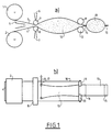
- FIG. 1 there is shown a part of a packaging chain according to the invention.
- This part is a station for manufacturing the wedging means or wedge according to the invention.
- Such a station includes a reserve 1-2 of a flexible support 3-4 constituted by a plastic film.
- this film is composed of two sheets each wound on a reel 1 or 2 at the entrance to the packaging line.
- the second step consists in constituting the wedging means preferably on the packaging site itself.
- wedging means for example in the form of a band of indefinite length which carries a large number of wedging means which will each be cut on the packaging site.
- a single block manufacturing station according to the invention can be installed at the head of the packaging lines, several packaging or packaging stations then receiving the setting means on demand.
- two sheets of flexible plastic are wound on the reels 1 and 2 and are unwound during the manufacturing process of wedging means or shims.
- the drawn sheets pass between knobs 8 and 9.
- At least one nozzle for injecting a blowing agent 5 makes it possible to form a cushion 10 which is an embodiment of a damping element of the invention.
- the configurable shape of the cushion 10 can be seen.
- Two welding heads 17 can deviate during the movement of the two sheets. They act during the longitudinal movement of the strip and can themselves move in the perpendicular direction 16. As the injection can be done with a configurable pressure on the nozzle 5, it is understood that all forms of cushions are possible.
- Means 11 and 12 make it possible to cut the lateral parts of the support which are surplus and they are wound on driving wheels 19 and 20. It is these wheels 19 and 20 which control the speed of travel of the strip.
- the strip along which the wedging means according to the invention succeed one another is constituted by a succession of spacer elements (the cushions 10 and 13) separated by thin parts 14 which serve, as we will see in the following, a hinge for two parts of the wedge.
- a cushion 10 is terminated by welding using knobs 6 and 7, shown in the inactive position in the drawing.
- the injection is then either cut or considerably reduced so as to produce parts 14, 15 on the strip whose thickness is reduced.
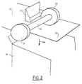
- FIG 2 there is shown another embodiment of a wedging means according to the invention which is visible there only in part and also in another phase of the packaging process of the invention: the phase of insertion into a container.
- the term “container” in fact designates any kind of packaging, any means intended to constitute a packet or packaged parcel in which the hold of the invention plays its role around a product.
- the container 36 is a cardboard box which has an upper opening 36a through which the product 33 to be packaged is introduced. Only a bottom corner of the rectangular product is shown.
- This elongated strip comprises a succession of cushions or spacing elements such as the element 31, 32, 34 in the form of a dumbbell.
- a central part 34 is intended to make contact between a part of the product and the corresponding inner face of the container 36.
- the part of the product 33 is its lower corner.
- the two side parts 31 and 32 are components of the spacer, the function of which is to separate the product from the side walls of the container. It is noted that these two components of the spacer are obtained by displacements of welding heads along an axis perpendicular to that of the unwinding of the support during the manufacture of the shim.
- the element 31, 32, 34 is connected to its two neighbors not shown in the hold by flat parts 30 and 35.
- hinges which thus allow the hold to surround at least partially the product.
- FIG 3 there is shown another embodiment of a wedging means according to the invention.
- Two sheets 42 and 43, one high, the other low, are superimposed and locally cushions like the cushion 40 are formed by injection of a blowing agent.
- blowing agent is held in the cushions by welds 41 which thus limit empty parts, or almost empty of blowing agent 39 which thus serve as a hinge, but also as a connecting element between the spacing elements 40 of the band of shims.
- the strip shown in FIG. 3 is standardized. It is used to package a wide variety of products with a constant dimension ratio. It is thus possible by adjusting the respective lengths L and l respectively of the spacer and of the connecting part to adapt to a large number of situations.
- Such a strip can be delivered on the packaging line without a shim manufacturing station and cut on demand.
- FIG 4 there is shown a partial section of a package or package formed according to the invention.
- a box 44 contains a product 45 and a block 46, 47, 48 is interposed between the two so that the spacer 46 is placed on a corner of the product.
- the element 46 is always produced with the technique of the support with two films as it is visible on the two hinges 48 and 47.
- FIG. 5 another embodiment is shown according to which the spacing elements 51, 52, 53 are cushions which bear on the faces of the product 50 and are interposed inside the box 49. note that two cushions are separated by short hinges between the welds of each cushion.
- the wedge of the invention is always constituted on a thin support in the form of an elongated strip of indefinite length but cut to the desired length to at least partially surround the product to be packaged.
- the shim manufacturing station includes a reserve of the flexible support 57 which takes place in the direction 58.
- an automaton 55 deposits spacing elements 65, 67.
- an automaton 56 Before removing the element spacing, an automaton 56 has a means for fixing the spacing element 65 on the relevant face of the flexible support.
- the automaton 55 deposits the spacer element 65 in synchronism with the unwinding 58 of the support.
- An element 67 is already deposited and the assembly is routed to the product loading station 64.
- the product 64 is brought by an automaton 63 which places it above the opening of a box 59 itself brought by an automaton 60, 61.
- the wedge is moved by the system already described in FIG. 1, where the lateral excess parts of the flexible support are cut from the rest of the strip and wound on rollers 62.
- the cutting is carried out by knives 68.
- the knife 66 cuts the strip perpendicular to the direction 58.
- the product is then introduced through the opening of the container 59 so that the spacer elements of the shim are placed in the desired relative position.
- FIG 7 there is shown another embodiment of a wedge according to the invention.
- the flanges 73, 74 may be in greater number (3 or more). They can also be interrupted by welds made in the direction perpendicular to the direction of the strip to produce cushions separated by hinges in the longitudinal direction.
- the container is not a specific necessity of the invention. It can be achieved by the flexible support itself.
- FIG 8 there is shown a package formed according to the embodiment of the invention in Figure 7 by relating the corresponding pins.
- the two flanges 73 and 75 which serve as spacers completely surround the product 79 packaged. They are here arranged on the solid surface of the faces of the product, but it will be seen later that, for certain applications, it is preferable that the shim is placed on the corners of the product.
- these two spacing elements 73 and 74 are manufactured on a support made of a mechanically resistant and heat-shrinkable plastic material, it is possible to produce the container directly with this support constituting the shim of the invention.
- the package is manufactured on the packaging line by introducing the wedge-product assembly into a former which temporarily acts as the container of Figure 6.
- a flap machine the excess of shim on the side which remains free and performs, by means known to a person skilled in the art, a weld 76 of the ends of the strip constituting the wedging means.
- a kind of withdrawal 78 on which we know how to execute gripping means which will make the package a transportable element.
- the lateral faces of the package in the shaper that is to say the faces which are not directly surrounded by the longitudinal wedge, are heated so that the excess parts 77 of the support retract and give mechanical cohesion to the package. Then the package is extracted by the gripping means provided on the flap 78.
- this packaging is that it makes it possible to replace the cardboard boxes in particular.
- Another notable advantage it allows using a translucent support to present the product while in the opaque packaging of the prior art, only an image deposited on the opaque container by a graphic process allowed the user to know the packaged product. It is therefore no longer necessary to open the package to get an idea of the product it contains or its condition after storage or transport.
- FIG 9 there is shown another embodiment of a wedge according to the invention.
- the spacing elements are studs of circular base deposited on an elongated support 80. They are divided into two groups 81 and 82 intended to garnish after the introduction into a container or a shaper the eight corners of the product. Note however that such a solution is not exclusive of parallelepiped products, but on the contrary it applies to all forms of products, regular or not.
- the wedge 80 is shown in the packaging process before its introduction into the shaper or the container 83a.
- the product 83 is arranged on the block so that it is balanced on the spacers. This means that there are as many spacing elements to the left of the shaper 83a as there are to the right before insertion therein.
- the package is protected over most of its periphery by the flexible support 80 heat-shrunk around the product 83 and it is protected on its corners for the most frequent drops and shocks by the elements of spacing on its eight corners. It is also noted that the flexible support is spaced from the walls of the product 83 which contributes, as in the conventional solution with a container such as a box, to prevent external attacks from reaching the product 83.
- the flexible support does not need to be welded or heat shrunk.
- FIG. 10 another type of wedging according to the invention has been shown, which always comprises an elongated support in the form of a band of indefinite length cut on demand and spacing elements formed on this support which are sometimes also intended to act as a shock absorber in the event of falls or similar events.
- the spacer element is unitary or discrete, that is to say that its manufacture can be distinct from that of the rest of the wedge and that there are several of them. packing block.
- the spacer element is formed by forming a thick plate (typically a few millimeters) of a plastic material such as polyurethane.
- the sheet 87 is formed in a cup provided with two lateral wings which are intended either to come to press on one side of the product, or else to come to rest on an internal face of the container.
- the bucket has two vertical faces 85 and 89 which connect the wings 87 with a bottom which is substantially parallel to them.
- this cup is of generally frustoconical or pyramidal shape in order to allow that, before the manufacture of the wedging means "on demand", a large quantity of spacers is stored near the manufacturing station of the hold under a reduced volume. This solution also saves transport costs if the spacers are not produced on the packaging line by reducing the volumes transported.
- a stack 84 of spacers according to the invention in the form of buckets is arranged in an automatic machine for installing the spacers.
- This automaton not shown in FIG. 10, but within the reach of those skilled in the art, first of all realizes a means of fixing the spacer element on the support initially stored on a reserve wheel 90.
- This wheel 90 is driven by the traction in the direction 92 due to means 93 like those explained in FIG. 1.
- Such means are tractors of excess lateral parts of the support strip after cutting in the loading area 95. It is noted that these motor means must be disposed beyond this loading area to allow the full effectiveness of the invention. Indeed, in particular in the case of an introduction of the product by gravity, the wedge before its cutting also serves as a means of carrying the product during the introduction. It is only during this that the cutting of the excess lateral parts is carried out.
- the automatic device for constituting the spacing elements on the support 90 comes to deposit for fixing, for example by gluing, at least one spacing element on the opposite face of the support in direction 91. It is noted that the synchronism of this removal 91 with the unwinding of the support 92 ensures a configurable positioning of the spacing elements relative to the product to be packaged in real time.
- the speed of travel of the support in the direction 92 can be temporarily canceled to allow the operation of depositing a spacer element.
- the wedging element comprises, from an initial sheet, three frustoconical cavities or cups whose functions differ.
- the lateral fins 97 make it possible to give support to the spacer element as will be seen below.
- the central cavity 98 in FIG. 12 has the function of receiving a part of the periphery of the product to be packaged, whether it is an angle or corner of the product or a face or portion. In fact, only the lateral edges 98a and 98b of the central cavity 98 are in contact with the product. The bottom of this cavity 98 remains away from the product to perform the spacing function.
- the central cavity 98 is damping.
- its profile is in the form of a bellows to constitute a spring whose stiffness can be adapted to the fragility of the product and to the environment in which it is stored or transported during the time it is conditioned.
- the two lateral cavities or cups 96a and 96b have the function of producing a separation of the product from its container on the lateral faces relative to the setting.
- Their frustoconical shape also ensures the nesting characteristic and can be completed by a shape in bellows for producing a shock absorbing spring and other energy transmissions in a direction perpendicular to the direction of setting.
- FIG 17 there is shown an embodiment of a package using a bucket block as in Figures 10 to 13.
- the product 123 is enclosed in a container 120 like a cardboard box.
- the cups of these spacers are arranged on the corners of the product 123.
- the support completely surrounds the product. In the event that no box like 123 is provided, it is always possible if the material of the support lends itself to it to make a container by welding the free ends of the wedge after cutting and by performing a shrinkage by heating the entire support.
- FIG 13 there is shown another embodiment of a wedging means according to the invention of the type with spacer elements in the form of a cushion filled with a blowing agent.
- a wedging means according to the invention of the type with spacer elements in the form of a cushion filled with a blowing agent.
- the wedge is produced on a support 99 of indefinite length cut on demand to the dimension required by the product to be packaged.
- This support comprises lateral parts 100 and 101 intended in part to ensure the drive of the support 99 on the packaging line, and for the rest after cutting to achieve at least partial lateral protection of the product after forming in the package shaper.
- the setting is shown seen from above before introduction into the shaper.
- Two spacing elements are provided 102 and 103 on either side of the product so that these two elements are arranged around the vertical faces (relative to the drawing) of the product and on their angles.
- the base 104 of the product rests on first transverse parts of the spacer elements which are obtained by a first welding perpendicular to the main dimension of the support in two sheets.
- first welding perpendicular to the main dimension of the support in two sheets.
- Welding members are provided both in the direction of the strip or longitudinal direction and welding means are provided in the direction orthogonal to the previous one, or transverse direction.
- the first spacer 103 to pass to the shimming manufacturing station is produced by a first transverse weld 103a of the two sheets of the support. Then, the injection of blowing agent is started. In this way, by setting the injection agent flow rate or by adjusting the longitudinal running speed of the support 99, a transverse rod of determined size.
- welding means perform welding of the exteriors 103b of the spacer 103. This welding will be maintained throughout the duration of travel of the support for the manufacture of the spacer 103.
- a transverse welding whose position and length can be configured as a function of the desired shape of the rod, is executed.
- a transverse welding is carried out to start the manufacture of the last transverse rod of the spacer element 103.
- the manufacture of the second spacer 102 is started in the same way.
- FIG. 14 the package produced according to the method described in FIG. 13 is shown.
- the two elements 102 and 103 have been manufactured in such a way that their external dimensions "catch up" with the non-uniformity of the shape of the product 105. They occupy the corners of the product and the support has been welded by its free edges 99, 106 of the FIG. 13 to constitute a gripping means 107.
- the excess part 101 which has not been cut to carry out the support of the support at the manufacturing station is folded down on the lateral face of the product after hot shrinking of the support in a shaper as has already been described.
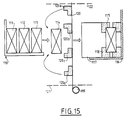
- FIG. 15 there is an application of the invention for producing a single package of several products.
- the invention also works for an introduction of the wedge-product assembly other than by gravity or along a vertical axis.
- An automaton 110 loads a succession of products which may have variable packaging characteristics in a single container.
- Five products 111 to 115 are provided, product 115 being already installed in the container 117 brought to the loading station 116 of the packaging line.
- the continuous support strip is supplied as already described by a reserve 119.
- the wedge is manufactured as has already been described between positions 121 and 122 where knives cut the wedge as the product wedge assembly 114 is introduced into the container by a loading arm. (not shown) in the direction of the arrows.
- the products are pushed successively so as to completely fill the container 117.
- the balanced edges of the shim 120 are gradually folded down around the product when it is introduced into the container 117.
- spacers 120a to 120d are arranged to line the four corners of the product 114 as it was already practiced on the first product installed 115.
- the four spacers as 120a to 120d are deposited on the support so as to wedge the single rightmost face of the product 115 which abuts at the bottom of the container 117.
- Two spacing elements as shown in the drawing are arranged on the face to the left of product 115. These are the outermost spacers of the wedging means. They are given a T shape so that the rightmost side of the next product (here 114) comes to be embedded in these two elements.
- a single block 140-142 is provided which includes eight cushions.
- the invention here makes it possible to constitute shims with 2N + 2 cushions if one wishes to package N products in a single package.
- the shim is manufactured continuously.
- N + 1 cushions are manufactured first, taking into account the dimensions of the N products that we want to package.
- the cushions most upstream of the process are manufactured before the introduction of the N products, but, the invention also applies to a successive manufacture of these N + 1 cushions most upstream as the products are introduced.
- the first product 133 is approached by the wedging means in the loading area.
- the two cushions 136 and 137 at the bottom of the package are connected by the support 134 and descend into the container 130.
- the N products are introduced into the package as the wedging means unfold in front of a control member of the loading operation.
- the N products thus follow the direction 135 until touching the bottom of the container 130, which completes the loading operation.
- an automaton performs the closure 138 of the opening of the container and ensures its fixing, the package constituted is evacuated and the operation can start again.
- FIG. 16 can be like the rest of the invention carried out both with a container of the type of a cardboard box and with a shaping device which shapes the support of the wedge of the invention.
- the support 150 carries two spacers 153 and 154 whose hollow shapes complement each other to allow the product to be completely wedged on the one hand and produce a compact package whose spacers are contiguous and even in certain embodiments not shown, nested.
- Each spacer has two projections on a base, the two projections of each of the spacers being in orthogonal directions two by two.
- the first wedging element 154 has two projections 158 and 159 transverse to the direction of the support 150, while their counterparts 156 and 157 of the second spacer element 153 are longitudinal.
- Their respective spacings L and l are substantially equal to the dimensions of the product 155 to be packaged, as well as the two depths of the spacing elements not visible in view a, have for sum the value of the height of the product.
- the excess lateral parts 152 and 151 after hot shrinkage, constitute a cutout 162 visible on the two lateral faces of the product and the free edges of the support are assembled at 160 to constitute a gripping element.
- spacers are made from thermosetting resins which are used as blowing agents in the process of the invention and which are in fact molded in the former.
- the wedging means can be constituted by a stamped in a material of controlled rigidity such as, for example, polyurethane.
- these spacer elements are produced in a unitary manner and placed according to the method of FIG. 6 for example.
Landscapes
- Engineering & Computer Science (AREA)
- Mechanical Engineering (AREA)
- Buffer Packaging (AREA)
- Container Filling Or Packaging Operations (AREA)
- Containers And Plastic Fillers For Packaging (AREA)
- Auxiliary Devices For And Details Of Packaging Control (AREA)
- Packages (AREA)
- Medical Preparation Storing Or Oral Administration Devices (AREA)
- Basic Packing Technique (AREA)
- Wrappers (AREA)
Claims (17)
- Verfahren zum Verpacken wenigstens eines Produkts in einem Behälter, wobei eine Ausfütterung oder ein Verkeilungsmittel zwischen den Behälter und das Produkt gesetzt wird, bei dem das Verkeilungsmittel in einem ersten Schritt zumindest teilweise am Verpackungsort, "nach Bedarf" kontinuierlich und in Form eines Bandes unbestimmter Länge hergestellt wird, dann das Verkeilungsmittel in einem zweiten Schritt zwischen den Behälter und wenigstens ein in die Nähe gebrachtes Produkt gesetzt wird und schließlich das Verkeilungsmittel im Laufe eines dritten Schritts durch Einfügen des Produkts in den Behälter zwischen die Innenwände des Behälters und das verpackte Produkt gesetzt wird, während eventuell die restliche Ausfütterung im Lauf der Einführung des oder der Produkte hergestellt wird, wobei dagegen zur Herstellung des Verkeilungsmittels auf einem geschmeidigen Träger wie einem wärmeschrumpfbaren Kunststoffilm (3, 4, 57) Abstandselemente (10, 13, 65, 67) angeordnet werden, dadurch gekennzeichnet, daß es außerdem darin besteht, als zeitweiligen Behälter eine Schrumpfeinrichtung anzuordnen, die im Lauf eines zusätzlichen Schritts des Verfahrens eine Wärmeschrumpfung des Trägers des Verkeilungsmittels durchführt, nachdem dessen freie Ränder verschweißt worden sind.
- Verfahren nach Anspruch 1, dadurch gekennzeichnet, daß es darin besteht, dann an dem mit einem überschüssigen Teil der freien Ränder des Trägers des Verkeilungsmittels gebildeten Umschlag nach ihrem Verschweißen ein Greifmittel vorzusehen.
- Verfahren nach Anspruch 1 oder 2, dadurch gekennzeichnet, daß das Verkeilungsmittel dadurch erhalten wird, daß einheitliche Abstandselemente an in Abhängigkeit von den Eigenschaften des zu verpackenden Produkts parametrierten Positionen auf einer Seite des Trägers des Verkeilungsmittels abgesetzt werden.
- Verfahren nach Anspruch 3, dadurch gekennzeichnet, daß es darin besteht, zwischen jedem Abstandselement und dem Träger ein Fixiermittel wie Kleber aufzubringen.
- Verfahren nach Anspruch 1 oder 2, bei welchem das Verkeilungsmittel durch Einspritzen eines Blähmittels zwischen zwei Folien des Trägers hergestellt wird, die während des Vorbeilaufens des Trägers vor der Station zur Herstellung der Ausfütterung fortschreitend verschweißt werden, wobei das Verschweißen in zwei Richtungen, erstens in Längs- und zweitens in Querrichtung durchgeführt wird, so daß alle Formen von Kissen erhalten werden, dadurch gekennzeichnet, daß das Blähmittel beim Durchgang des gebildeten Packstücks in einer Schrumpfeinrichtung wärmegehärtet wird.
- Für das Verfahren der Erfindung geeignetes Verkeilungsmittel, das wenigstens einen geschmeidigen Träger mit gestreckter Form unbestimmter Länge aufweist, der dazu bestimmt ist, am Verpackungsort auf die erforderliche Abmessung zugeschnitten zu werden, wobei der Träger an bestimmten Positionen Abstandselemente für das zu verpackende Produkt trägt, dadurch gekennzeichnet, daß der Träger wenigstens aus einer Folie aus einem mechanisch widerstandsfähigen und wärmeschrumpfbaren Kunststoffmaterial besteht.
- Verkeilungsmittel nach Anspruch 6, das wenigstens zwei miteinander zur Bildung von mit einem Blähmittel gefüllten Kissen oder Wülsten verschweißbare Folien aufweist, dadurch gekennzeichnet, daß das Blähmittel mechanische Eigenschaften aufweist, die eine Stoßdämpfung ermöglichen.
- Verkeilungsmittel nach Anspruch 7, dadurch gekennzeichnet, daß das Blähmittel so wärmehärtbar ist, daß die Formung der als Abstandselemente dienenden Kissen oder Wülste ermöglicht wird.
- Verkeilungsmittel nach Anspruch 6, dadurch gekennzeichnet, daß die wärmeschrumpfbare Folie so nach außen angeordnet ist, daß die Herstellung eines kohärenten und homogenen Packstücks um das zu umhüllende Produkt durch den Durchgang durch eine Heizschrumpfeinrichtung ermöglicht wird.
- Verkeilungsmittel nach Anspruch 9, dadurch gekennzeichnet, daß die freien Ränder des Trägers des Verkeilungsmittels verschweißt werden, um einen Umschlag zu bilden, der auch Mittel zum Greifen des Packstücks trägt.
- Verkeilungsmittel nach Anspruch 6, dadurch gekennzeichnet, daß die Abstandselemente mit wenigstens einem kegelstumpf- oder pyramidenförmigen Napf versehen sind, so daß vor dem Aufsetzen auf den Träger der Ausfütterung ihre Lagerung ermöglicht wird.
- Verkeilungsmittel nach Anspruch 11, dadurch gekennzeichnet, daß die Verkeilungselemente einen zentralen Napf aufweisen, der dazu bestimmt ist, das Produkt von den Wänden des Behälters, der Kiste oder des Trägers der wärmegeschrumpften Ausfütterung in der Ebene einer ersten Richtung im Abstand zu halten, und von wenigstens zwei seitlichen Näpfen umgeben ist, die dazu bestimmt sind, das Produkt in einer im wesentlichen zur ersten Richtung senkrechten Richtung von den Innenwänden des Behälters im Abstand zu halten.
- Verkeilungsmittel nach Anspruch 12, dadurch gekennzeichnet, daß die Abstandselemente ineinandergesetzt werden können.
- Verpackungsstraße mit wenigstens einer Station zur Herstellung eines Verkeilungsmittels nach einem der Ansprüche 6 bis 13, die einerseits in einer Absetzzone aufweist:- einen Vorrat an geschmeidigem Träger (1, 2, 57), der aus wenigstens einer Folie aus einem mechanisch widerstandsfähigen und wärmeschrumpfbaren Kunststoffmaterial besteht,- sowie Mittel (5, 8, 9, 17) zum Bilden der Abstandselemente an dem Träger (3, 4) und wenigstens eine Station zum Laden von wenigstens einem Produkt in einen Behälter;und auch Motormittel für den Träger des Verkeilungsmittels in einer Längsrichtung relativ zu der gestreckten Form des Trägers, dadurch gekennzeichnet, daß die Motormittel für den Träger durch Räder (19, 20) gebildet sind, die die überschüssigen seitlichen Teile des Trägers des Verkeilungsmittels einrollen, die während des Ladens der Einheit aus der Ausfütterung und dem Produkt in einen zeitweiligen Behälter abgeschnitten werden, eine Schrumpfeinrichtung, die im Lauf eines zusätzlichen Schritts des Verfahrens nach Anspruch 1 bis 5 eine Warmschrumpfung des Trägers des Verkeilungsmittels durchführt, nachdem dessen freie Enden verschweißt worden sind.
- Verpackungsstraße nach Anspruch 14, dadurch gekennzeichnet, daß die Mittel zum Formen der Abstandselemente in Abhängigkeit von den geometrischen und verpackungsmäßigen Eigenschaften des an der Ladestation anwesenden Produkts mit der Längsverschiebung des Trägers des Verkeilungsmittels synchronisiert sind.
- Verpackungsstraße nach Anspruch 15, dadurch gekennzeichnet, daß die Mittel zum Bilden der Abstandselemente Köpfe zum Schweißen der beiden den Träger bildenden Folien in wenigstens einer Richtung senkrecht zu der Verschiebung des Trägers und eventuell in einer zweiten senkrechten, sogenannten Querrichtung, wobei die beiden Reihen von Köpfen synchron mit der Verschiebung des Trägers aktiv und in Abhängigkeit von den geometrischen und verpackungsmäßigen Eigenschaften des an der Ladestation anwesenden Produkts parametrierbar sind.
- Verpackungsstraße nach einem der Ansprüche 14 bis 16, dadurch gekennzeichnet, daß sie auch eine Packstückschrumpfeinrichtung aufweist, die durch einen Hohlraum gebildet ist, der bei der Ladeoperation einen zeitweiligen Behälter für die Einheit aus der Ausfütterung und dem Produkt bildet und dann dem Packstück beispielsweise durch Warmformung der äußeren Folie des Trägers eine kohärente und dauerhafte Form verleiht.
Applications Claiming Priority (2)
| Application Number | Priority Date | Filing Date | Title |
|---|---|---|---|
| FR8814767 | 1988-11-14 | ||
| FR8814767A FR2639024B1 (fr) | 1988-11-14 | 1988-11-14 | Procede de conditionnement, cale de conditionnement et chaine de conditionnement |
Publications (2)
| Publication Number | Publication Date |
|---|---|
| EP0369871A1 EP0369871A1 (de) | 1990-05-23 |
| EP0369871B1 true EP0369871B1 (de) | 1994-01-19 |
Family
ID=9371817
Family Applications (1)
| Application Number | Title | Priority Date | Filing Date |
|---|---|---|---|
| EP89403120A Expired - Lifetime EP0369871B1 (de) | 1988-11-14 | 1989-11-13 | Konditionierungsverfahren, Verpackungseinlage und Konditionierungskette |
Country Status (7)
| Country | Link |
|---|---|
| US (2) | US5022217A (de) |
| EP (1) | EP0369871B1 (de) |
| JP (1) | JPH07115692B2 (de) |
| CA (1) | CA2002706C (de) |
| DE (1) | DE68912527T2 (de) |
| ES (1) | ES2050265T3 (de) |
| FR (1) | FR2639024B1 (de) |
Families Citing this family (17)
| Publication number | Priority date | Publication date | Assignee | Title |
|---|---|---|---|---|
| DE9005277U1 (de) * | 1990-05-09 | 1991-02-14 | Edelhoff Polytechnik Gmbh & Co, 58640 Iserlohn | Aufnahmeeinrichtung für vorzugsweise gefährdende Substanzen |
| US5950875A (en) * | 1995-11-30 | 1999-09-14 | Sealed Air Corporation | Modular foam dispenser |
| FR2773307B1 (fr) * | 1998-01-06 | 2000-03-24 | Philippe Schneider | Bouclier amortisseur pour sac de transport d'un microordinateur portable ou autre objet technique |
| DE29805763U1 (de) | 1998-03-30 | 1998-07-02 | HDM Holz-Dammers GmbH, 47441 Moers | Vorrichtung zur Herstellung von aus Pappe, Karton o.dgl., insbesondere Graupappe, Wellpappe oder mehrschichtiger Wellpappe bestehenden Kopfschonern |
| IT1308431B1 (it) * | 1999-03-15 | 2001-12-17 | Novamont Spa | Elementi per imballaggio |
| JP4666843B2 (ja) * | 2001-09-03 | 2011-04-06 | リコーエレメックス株式会社 | 包装用緩衝装置 |
| US20050108993A1 (en) * | 2003-11-25 | 2005-05-26 | Xerox Corporation | Air bladder packing system and process for using the same |
| US7607911B2 (en) * | 2006-04-26 | 2009-10-27 | Sealed Air Corporation (Us) | Method and apparatus for making foam-in-place cushions with selective distribution of foam |
| US7694664B1 (en) * | 2009-01-09 | 2010-04-13 | Robert Bosch Gmbh | Fuel rail damper |
| US8586165B2 (en) | 2009-03-16 | 2013-11-19 | Storopack, Inc. | Method and machine for making foam cushions |
| US8356463B2 (en) * | 2009-09-30 | 2013-01-22 | Sealed Air Corporation (Us) | Apparatus for forming flexible containers, dispensing fluid into the containers, and enclosing the fluid within the containers |
| GB2477495A (en) * | 2010-02-01 | 2011-08-10 | Sky Packaging Ltd | Inflatable cushions |
| US9010075B2 (en) * | 2011-03-31 | 2015-04-21 | Dell Products Lp | Systems and methods for gas packaging |
| WO2017146577A1 (en) * | 2016-02-25 | 2017-08-31 | Generation Of Change B.V. | Foldable and biodegradable cushioning sheet |
| NL2016317B1 (en) * | 2016-02-25 | 2017-09-11 | Generation Of Change B V | Foldable and Biodegradable Cushioning Sheet. |
| DE102018200988A1 (de) * | 2018-01-23 | 2019-07-25 | Homag Automation Gmbh | Vorrichtung und Verfahren zum Anbringen eines Schutzelements an einer Verpackung |
| JP7498512B2 (ja) * | 2021-09-24 | 2024-06-12 | 株式会社崇雅 | トレイ及びトレイの製造システム |
Family Cites Families (23)
| Publication number | Priority date | Publication date | Assignee | Title |
|---|---|---|---|---|
| US3024935A (en) * | 1960-02-25 | 1962-03-13 | Vinick George | Banana packing means |
| US3131240A (en) * | 1960-11-09 | 1964-04-28 | Grace W R & Co | Protective padding |
| US3503838A (en) * | 1965-04-22 | 1970-03-31 | Mobay Chemical Corp | Laminated foam plastic article and method for making the same |
| US3339722A (en) * | 1965-10-08 | 1967-09-05 | Vanant Company Inc | Package and cushioning strip for fragile articles |
| US3412521A (en) * | 1967-02-06 | 1968-11-26 | Dow Chemical Co | Method for packing articles |
| US3667593A (en) * | 1970-03-30 | 1972-06-06 | John M Pendleton | Flowable dunnage apparatus and method of packaging with flowable and compliable inflated dunnage material |
| US3696580A (en) * | 1971-05-17 | 1972-10-10 | Joseph M Saltzer Sr | Shrink film packaging method |
| US3881601A (en) * | 1973-09-21 | 1975-05-06 | Possis Corp | Rack display package for dry cells and the like |
| US3987736A (en) * | 1975-03-17 | 1976-10-26 | Gordon M. Newby | Reusable pneumatic dunnage device |
| US4333570A (en) * | 1976-06-09 | 1982-06-08 | Owens-Illinois, Inc. | Merchandising package for containers |
| JPS5317491A (en) * | 1976-07-31 | 1978-02-17 | Matsushita Electric Ind Co Ltd | Packing machine |
| JPS5323792A (en) * | 1976-08-12 | 1978-03-04 | Sanyo Electric Co Ltd | Packing method by injecting/blowing synthetic resin |
| PT69087A (pt) * | 1978-02-03 | 1979-02-01 | Roth Jacques | Sac auto-expansible destine a des buts de remplissage d'emballage ou d'isolation et precede pour se mise en oeuvre |
| JPS5584648A (en) * | 1978-12-21 | 1980-06-26 | Asahi Dow Ltd | Method of making internal material for packing |
| JPS58126983U (ja) * | 1982-02-22 | 1983-08-29 | 安藤電気株式会社 | 製品収容箱 |
| JPS60134874A (ja) * | 1983-11-11 | 1985-07-18 | オリヒロ株式会社 | 緩衝材の製造方法ならびに製造装置 |
| JPS60134875A (ja) * | 1983-12-20 | 1985-07-18 | 株式会社東芝 | 包装装置 |
| US4620633A (en) * | 1985-09-30 | 1986-11-04 | Lookholder Theodore W | Protective envelope device for packaging fragile articles |
| FR2597839B1 (fr) * | 1986-04-25 | 1989-05-26 | Delamare & Cie Pierre | Nouveau conditionnement protecteur pour le transport et le stockage d'objets |
| US4856655A (en) * | 1987-09-28 | 1989-08-15 | Barsky Samuel M | Combination box and package cushioning and method |
| US4800708A (en) * | 1987-11-16 | 1989-01-31 | Sealed Air Corporation | Apparatus and method for forming foam cushions for packaging purposes |
| FR2626252B1 (fr) * | 1988-01-26 | 1990-05-18 | Bull Sa | Cale de conditionnement, conteneur pour une telle cale et procede d'emballage mettant en oeuvre une telle cale |
| JPH0213173A (ja) * | 1988-06-30 | 1990-01-17 | Canon Inc | ファクシミリ装置 |
-
1988
- 1988-11-14 FR FR8814767A patent/FR2639024B1/fr not_active Expired - Lifetime
-
1989
- 1989-11-07 US US07/433,005 patent/US5022217A/en not_active Expired - Lifetime
- 1989-11-10 CA CA002002706A patent/CA2002706C/fr not_active Expired - Lifetime
- 1989-11-13 EP EP89403120A patent/EP0369871B1/de not_active Expired - Lifetime
- 1989-11-13 DE DE89403120T patent/DE68912527T2/de not_active Expired - Lifetime
- 1989-11-13 ES ES89403120T patent/ES2050265T3/es not_active Expired - Lifetime
- 1989-11-13 JP JP1294779A patent/JPH07115692B2/ja not_active Expired - Fee Related
-
1991
- 1991-02-19 US US07/656,805 patent/US5145069A/en not_active Expired - Lifetime
Also Published As
| Publication number | Publication date |
|---|---|
| US5145069A (en) | 1992-09-08 |
| ES2050265T3 (es) | 1994-05-16 |
| FR2639024B1 (fr) | 1991-08-02 |
| JPH07115692B2 (ja) | 1995-12-13 |
| US5022217A (en) | 1991-06-11 |
| DE68912527T2 (de) | 1994-05-05 |
| FR2639024A1 (fr) | 1990-05-18 |
| EP0369871A1 (de) | 1990-05-23 |
| CA2002706A1 (fr) | 1990-05-14 |
| DE68912527D1 (de) | 1994-03-03 |
| JPH02242702A (ja) | 1990-09-27 |
| CA2002706C (fr) | 1996-03-05 |
Similar Documents
| Publication | Publication Date | Title |
|---|---|---|
| EP0369871B1 (de) | Konditionierungsverfahren, Verpackungseinlage und Konditionierungskette | |
| EP0977690B1 (de) | Pappschachtel zum verpacken einer gruppe von artikeln | |
| WO1999029589A2 (fr) | Etui pour produits tels que des lingettes humides | |
| CA2228892A1 (fr) | Contenant livre a plat, puis mis en volume en deux phases distinctes, et portant de l'adhesif a effet prolonge | |
| FR3115269A1 (fr) | Colis intégrant des moyens de retenue d’un objet | |
| FR2506722A1 (fr) | Emballage pour le conditionnement de lots d'objets et procedes de realisation d'un tel emballage et de conditionnement simultane des objets | |
| FR2729123A1 (fr) | Dispositif d'emballage et de presentoir, notamment pour des bicyclettes | |
| FR2661392A1 (fr) | Procede pour le conditionnement de lots de produits de volumes divers, dispositif pour la mise en óoeuvre de ce procede et conditionnement ainsi obtenu. | |
| EP0580516B1 (de) | Verpackungsverfahren und entsprechende Verpackung | |
| FR2604654A1 (fr) | Machine pour la fabrication d'emballage de produits sous feuilles retractables | |
| EP0697338B1 (de) | Verpackung für ein Produkt nichtspezifischer Form, Satz von Zuschnitten, Verfahren und Vorrichtung zur Herstellung einer solchen Verpackung | |
| WO2000043283A2 (fr) | Contenant en carton obtenu par pliage d'une bande, destine a des objets de hauteur variable | |
| CA3114195A1 (fr) | Dispositif et procede de rassemblement et de dechargement d'articles | |
| EP0369870B1 (de) | Verpackungselement sowie Verpackung mit einem solchen Element und Verpackungsverfahren | |
| EP0277844A1 (de) | Verfahren zum Einsetzen von Verpackungskleinprodukten in Behältern und System zur Anwendung des Verfahrens | |
| WO1999024247A1 (fr) | Procede et machine a barillet pour la mise en volume de caisses tambour ou analogue a partir de decoupes en carton | |
| EP2723645B1 (de) | Verpacken von in einer oder mehreren schichten positionierten gegenständen | |
| FR2484373A1 (fr) | Nouveau mode d'emballage sous film de plastique souple | |
| FR2770447A1 (fr) | Procede et machine a barillet pour la mise en volume d'une caisse tambour munie d'un film retractable a partir de decoupes en carton | |
| FR2649670A1 (fr) | Nouvel emballage autocollant en carton ondule ou compact et machine pour le fabriquer | |
| EP1228970B1 (de) | Oben offene Kartonschachtel mit Kartonhülle | |
| EP0680438A1 (de) | Verfahren zur herstellung und füllung einer verpackung mit mindestens einem gegenstand, insbesonders zur präsentation geeignet | |
| FR3103473A1 (fr) | Emballage modulable a dimensions ajustables | |
| FR2762302A1 (fr) | Assemblage de pochettes adhesives | |
| FR2639034A1 (fr) | Cale de conditionnement de type decoupe, machine de decoupe pour une telle cale et procede d'utilisation d'une telle cale |
Legal Events
| Date | Code | Title | Description |
|---|---|---|---|
| PUAI | Public reference made under article 153(3) epc to a published international application that has entered the european phase |
Free format text: ORIGINAL CODE: 0009012 |
|
| AK | Designated contracting states |
Kind code of ref document: A1 Designated state(s): BE CH DE ES FR GB IT LI SE |
|
| 17P | Request for examination filed |
Effective date: 19901103 |
|
| 17Q | First examination report despatched |
Effective date: 19920221 |
|
| RAP3 | Party data changed (applicant data changed or rights of an application transferred) |
Owner name: BULL S.A. |
|
| GRAA | (expected) grant |
Free format text: ORIGINAL CODE: 0009210 |
|
| AK | Designated contracting states |
Kind code of ref document: B1 Designated state(s): BE CH DE ES FR GB IT LI SE |
|
| GBT | Gb: translation of ep patent filed (gb section 77(6)(a)/1977) |
Effective date: 19940124 |
|
| REF | Corresponds to: |
Ref document number: 68912527 Country of ref document: DE Date of ref document: 19940303 |
|
| ITF | It: translation for a ep patent filed | ||
| REG | Reference to a national code |
Ref country code: ES Ref legal event code: FG2A Ref document number: 2050265 Country of ref document: ES Kind code of ref document: T3 |
|
| PLBE | No opposition filed within time limit |
Free format text: ORIGINAL CODE: 0009261 |
|
| STAA | Information on the status of an ep patent application or granted ep patent |
Free format text: STATUS: NO OPPOSITION FILED WITHIN TIME LIMIT |
|
| 26N | No opposition filed | ||
| EAL | Se: european patent in force in sweden |
Ref document number: 89403120.2 |
|
| REG | Reference to a national code |
Ref country code: GB Ref legal event code: IF02 |
|
| PGFP | Annual fee paid to national office [announced via postgrant information from national office to epo] |
Ref country code: FR Payment date: 20031126 Year of fee payment: 15 |
|
| BECA | Be: change of holder's address |
Owner name: *SEALED AIR CORP.PARK 80 EAST, US - SADDLE BROOK, Effective date: 20050308 |
|
| REG | Reference to a national code |
Ref country code: CH Ref legal event code: PFA Owner name: BULL S.A. Free format text: BULL S.A.#TOUR BULL, 1, PLACE CARPEAUX#PUTEAUX (FR) -TRANSFER TO- BULL S.A.#68 ROUTE DE VERSAILLES#78430 LOUVECIENNES (FR) |
|
| REG | Reference to a national code |
Ref country code: CH Ref legal event code: PUE Owner name: SEALED AIR CORPORATION Free format text: BULL S.A.#68 ROUTE DE VERSAILLES#78430 LOUVECIENNES (FR) -TRANSFER TO- SEALED AIR CORPORATION#PARK 80 EAST#SADDLE BROOK, NJ 07663-5291 (US) |
|
| REG | Reference to a national code |
Ref country code: GB Ref legal event code: 732E |
|
| PG25 | Lapsed in a contracting state [announced via postgrant information from national office to epo] |
Ref country code: FR Free format text: LAPSE BECAUSE OF NON-PAYMENT OF DUE FEES Effective date: 20050729 |
|
| REG | Reference to a national code |
Ref country code: FR Ref legal event code: ST |
|
| REG | Reference to a national code |
Ref country code: FR Ref legal event code: TP Ref country code: FR Ref legal event code: CA |
|
| PGFP | Annual fee paid to national office [announced via postgrant information from national office to epo] |
Ref country code: CH Payment date: 20061124 Year of fee payment: 18 Ref country code: SE Payment date: 20061124 Year of fee payment: 18 |
|
| PGFP | Annual fee paid to national office [announced via postgrant information from national office to epo] |
Ref country code: BE Payment date: 20061220 Year of fee payment: 18 |
|
| BECA | Be: change of holder's address |
Owner name: *SEALED AIR CORP.PARK 80 EAST, US - SADDLE BROOK, Effective date: 20050308 |
|
| BERE | Be: lapsed |
Owner name: *SEALED AIR CORP. Effective date: 20071130 |
|
| EUG | Se: european patent has lapsed | ||
| PG25 | Lapsed in a contracting state [announced via postgrant information from national office to epo] |
Ref country code: LI Free format text: LAPSE BECAUSE OF NON-PAYMENT OF DUE FEES Effective date: 20071130 Ref country code: CH Free format text: LAPSE BECAUSE OF NON-PAYMENT OF DUE FEES Effective date: 20071130 |
|
| REG | Reference to a national code |
Ref country code: CH Ref legal event code: PL |
|
| PG25 | Lapsed in a contracting state [announced via postgrant information from national office to epo] |
Ref country code: BE Free format text: LAPSE BECAUSE OF NON-PAYMENT OF DUE FEES Effective date: 20071130 |
|
| PG25 | Lapsed in a contracting state [announced via postgrant information from national office to epo] |
Ref country code: SE Free format text: LAPSE BECAUSE OF NON-PAYMENT OF DUE FEES Effective date: 20071114 |
|
| PGFP | Annual fee paid to national office [announced via postgrant information from national office to epo] |
Ref country code: ES Payment date: 20081126 Year of fee payment: 20 |
|
| PGFP | Annual fee paid to national office [announced via postgrant information from national office to epo] |
Ref country code: IT Payment date: 20081126 Year of fee payment: 20 |
|
| PGFP | Annual fee paid to national office [announced via postgrant information from national office to epo] |
Ref country code: DE Payment date: 20081223 Year of fee payment: 20 |
|
| PGFP | Annual fee paid to national office [announced via postgrant information from national office to epo] |
Ref country code: GB Payment date: 20081128 Year of fee payment: 20 |
|
| REG | Reference to a national code |
Ref country code: GB Ref legal event code: PE20 Expiry date: 20091112 |
|
| REG | Reference to a national code |
Ref country code: ES Ref legal event code: FD2A Effective date: 20091114 |
|
| PG25 | Lapsed in a contracting state [announced via postgrant information from national office to epo] |
Ref country code: GB Free format text: LAPSE BECAUSE OF EXPIRATION OF PROTECTION Effective date: 20091112 Ref country code: ES Free format text: LAPSE BECAUSE OF EXPIRATION OF PROTECTION Effective date: 20091114 |