EP0369891B1 - Méthode et dispositif pour palper automatiquement la configuration d'une aire de surface et pour y effectuer une opération d'usinage - Google Patents
Méthode et dispositif pour palper automatiquement la configuration d'une aire de surface et pour y effectuer une opération d'usinage Download PDFInfo
- Publication number
- EP0369891B1 EP0369891B1 EP89403177A EP89403177A EP0369891B1 EP 0369891 B1 EP0369891 B1 EP 0369891B1 EP 89403177 A EP89403177 A EP 89403177A EP 89403177 A EP89403177 A EP 89403177A EP 0369891 B1 EP0369891 B1 EP 0369891B1
- Authority
- EP
- European Patent Office
- Prior art keywords
- track
- working
- tool
- control circuit
- area
- Prior art date
- Legal status (The legal status is an assumption and is not a legal conclusion. Google has not performed a legal analysis and makes no representation as to the accuracy of the status listed.)
- Expired - Lifetime
Links
Images




Classifications
-
- B—PERFORMING OPERATIONS; TRANSPORTING
- B23—MACHINE TOOLS; METAL-WORKING NOT OTHERWISE PROVIDED FOR
- B23P—METAL-WORKING NOT OTHERWISE PROVIDED FOR; COMBINED OPERATIONS; UNIVERSAL MACHINE TOOLS
- B23P23/00—Machines or arrangements of machines for performing specified combinations of different metal-working operations not covered by a single other subclass
- B23P23/04—Machines or arrangements of machines for performing specified combinations of different metal-working operations not covered by a single other subclass for both machining and other metal-working operations
-
- G—PHYSICS
- G05—CONTROLLING; REGULATING
- G05B—CONTROL OR REGULATING SYSTEMS IN GENERAL; FUNCTIONAL ELEMENTS OF SUCH SYSTEMS; MONITORING OR TESTING ARRANGEMENTS FOR SUCH SYSTEMS OR ELEMENTS
- G05B19/00—Program-control systems
- G05B19/02—Program-control systems electric
- G05B19/42—Recording and playback systems, i.e. in which the program is recorded from a cycle of operations, e.g. the cycle of operations being manually controlled, after which this record is played back on the same machine
- G05B19/4202—Recording and playback systems, i.e. in which the program is recorded from a cycle of operations, e.g. the cycle of operations being manually controlled, after which this record is played back on the same machine preparation of the program medium using a drawing, a model
- G05B19/4207—Recording and playback systems, i.e. in which the program is recorded from a cycle of operations, e.g. the cycle of operations being manually controlled, after which this record is played back on the same machine preparation of the program medium using a drawing, a model in which a model is traced or scanned and corresponding data recorded
-
- G—PHYSICS
- G05—CONTROLLING; REGULATING
- G05B—CONTROL OR REGULATING SYSTEMS IN GENERAL; FUNCTIONAL ELEMENTS OF SUCH SYSTEMS; MONITORING OR TESTING ARRANGEMENTS FOR SUCH SYSTEMS OR ELEMENTS
- G05B2219/00—Program-control systems
- G05B2219/30—Nc systems
- G05B2219/39—Robotics, robotics to robotics hand
- G05B2219/39468—Changeable hand, tool, code carrier, detector
-
- G—PHYSICS
- G05—CONTROLLING; REGULATING
- G05B—CONTROL OR REGULATING SYSTEMS IN GENERAL; FUNCTIONAL ELEMENTS OF SUCH SYSTEMS; MONITORING OR TESTING ARRANGEMENTS FOR SUCH SYSTEMS OR ELEMENTS
- G05B2219/00—Program-control systems
- G05B2219/30—Nc systems
- G05B2219/45—Nc applications
- G05B2219/45104—Lasrobot, welding robot
-
- G—PHYSICS
- G05—CONTROLLING; REGULATING
- G05B—CONTROL OR REGULATING SYSTEMS IN GENERAL; FUNCTIONAL ELEMENTS OF SUCH SYSTEMS; MONITORING OR TESTING ARRANGEMENTS FOR SUCH SYSTEMS OR ELEMENTS
- G05B2219/00—Program-control systems
- G05B2219/30—Nc systems
- G05B2219/49—Nc machine tool, till multiple
- G05B2219/49362—Tool, probe at constant height to surface during machining
-
- G—PHYSICS
- G05—CONTROLLING; REGULATING
- G05B—CONTROL OR REGULATING SYSTEMS IN GENERAL; FUNCTIONAL ELEMENTS OF SUCH SYSTEMS; MONITORING OR TESTING ARRANGEMENTS FOR SUCH SYSTEMS OR ELEMENTS
- G05B2219/00—Program-control systems
- G05B2219/30—Nc systems
- G05B2219/50—Machine tool, machine tool null till machine tool work handling
- G05B2219/50153—Mount machining unit on workpiece, move unit on it
-
- G—PHYSICS
- G05—CONTROLLING; REGULATING
- G05B—CONTROL OR REGULATING SYSTEMS IN GENERAL; FUNCTIONAL ELEMENTS OF SUCH SYSTEMS; MONITORING OR TESTING ARRANGEMENTS FOR SUCH SYSTEMS OR ELEMENTS
- G05B2219/00—Program-control systems
- G05B2219/30—Nc systems
- G05B2219/50—Machine tool, machine tool null till machine tool work handling
- G05B2219/50214—Refurbish, refinish, reprofile, recondition, restore, rebuild profile
-
- G—PHYSICS
- G05—CONTROLLING; REGULATING
- G05B—CONTROL OR REGULATING SYSTEMS IN GENERAL; FUNCTIONAL ELEMENTS OF SUCH SYSTEMS; MONITORING OR TESTING ARRANGEMENTS FOR SUCH SYSTEMS OR ELEMENTS
- G05B2219/00—Program-control systems
- G05B2219/30—Nc systems
- G05B2219/50—Machine tool, machine tool null till machine tool work handling
- G05B2219/50356—Tool perpendicular, normal to 3-D surface
Definitions
- the present invention relates to a method and apparatus for automatically sensing the configuration of a surface area of an object, such as a portion of a hydraulic turbine runner of a power generating station, and effecting a work function such as the repair of cavitation damage thereon, and more particularly to the use of a robotic system for the in-situ repair of such damage.
- the present invention originated by solving the problem of repairing hydraulic turbine runners in power stations which are often damaged by cavitation due to erosion. Such runners are often subjected to severe damage requiring extensive repair which is extremely costly due to the lengthy down time of the runner and because of the difficulty in effecting such repairs.
- the most economical way of repairing such turbines is to perform the work with the runner remaining in the turbine pit.
- the steps involved in the repair include air-arc gouging and/or grinding to remove unsound metal, followed by welding to fill the gouged-out areas. Finally, the weld-filled cavity must be ground to restore optimum blade profile.
- Another feature of the present invention is to provide a method and apparatus using a robotic system for automatically sensing the configuration of a surface area of an object, and effecting a work function thereon in situ.
- Another feature of the present invention is to provide a method and apparatus which is small, portable, self-programming and easily attachable to a work surface for automatically sensing the configuration of a surface area of the said surface and effecting a work function.
- Another feature of the present invention is to provide a method and apparatus for automatically sensing the configuration of a surface area of an object and effecting a work function, and wherein a robotic system is utilized which self-programs the work function and automatically effects the work thereto while providing the option of an operator intervention to command or assist in the determination and sequence of work procedures.
- Another feature of the present invention is to provide a method and apparatus for automatically sensing the configuration of a surface area of an object, such as on a hydraulic turbine runner, and effecting a work function to repair cavitation damage or imperfections thereon, and wherein said work function comprises gouging, welding and grinding.
- Another feature of the present invention is to provide a method and apparatus for automatically sensing the configuration of a surface area of an object and effecting a work function, and wherein the apparatus is substantially all automatic and easy to install and operate.
- the present invention provides an apparatus for automatically sensing the configuration of a surface area of an object, and effecting a work function thereon.
- the apparatus comprises a track connectible relative to the surface.
- a motor-actuated robot member is connectible to the track and has a motorized element provided with track coupling means engaged with the track for displacing the robot member at a predetermined rate and position along the track.
- a working arm is displaceably coupled to the robot member. The working arm has one or more working tools connectible thereto.
- a control circuit is associated with the robot member for displacing same and operating the working arm and tool.
- a sensor is connected to the working arm and has a probe to sense a distance which is measured along a normal of said surface or any surface calculated by said control circuit assumed to be representative of said surface in a delineated working environment of the robot member and working arm.
- the sensor feeds information data of the X, Y and Z coordinates to the control circuit to determine the geometry of the surface of the working environment and contour of areas in the working environment requiring a work procedure to be effected by the one or more working tools.
- a method of automatically sensing the configuration of a surface area and effecting a work function thereon comprises the steps of connecting a support track over a section of the surface area.
- the track has motor-actuated robot member connected thereto and equipped with a working arm displaceably coupled therewith.
- a sensor is connected to the working arm and a control circuit is associated with the robot member.
- the robot member and working arm are displaced along X and Y coordinates respectively, of a delineated working environment adjacent the tracks while sensing the distance between the surface and a reference point of the arm along the Z coordinate, and producing and storing information data signals relating to X, Y and Z coordinates to determine the surface configuration of the surface area whereby to detect irregular surface areas within the working environment.
- a series of coordinate points are then selected about an irregular surface area to determine a reference plane based on three of the points, and to find the projection of all points on this plane to determine the polygonal contour in the plane and store information signals representative thereof.
- a tool is selected and connected to the working arm and effects a work function in the polygonal contoured area.
- the robotic apparatus of the present invention which automatically senses the configuration of a surface, herein the surface of a blade portion 11 of a hydraulic turbine runner 12.
- the apparatus comprises a track 13 herein supported elevated from the metal surface 11 by a track support 14. Both the track support 14 and the track 13 are shaped to the configuration of the surface 11.
- the track support 14 is maintained elevated from the surface 11 by adjustable support legs 15 which are immovably secured to the surface 11 by means such as tack welds 16, as shown in Figure 2.
- the support legs 15 are also pivotally connected to the track support 14 by a hinge connection 17.
- An adjustment bolt 18 extends through a slot 19 provided in the legs 15 to provide adjustment of the length thereof. Pivot joint and the adjustment bolt provide for finite adjustment for the proper positioning of the track over the working surface 11 whereby the track is substantially parallel to the surface.
- the apparatus of the present invention comprises a motor-actuated robot member 20 which is connectible to the track 13 through a track coupling gear 21 which is driven by a motor 22 provided within the robot member 20 whereby to displace same at a predetermined rate and position along the track 13.
- a working arm 23 is displaceably coupled to the robot member and extends transverse to the track 14.
- the working arm 23 is also provided with one or more working tools 24, as will be described later, which is connectible to the arm.
- a sensor 25 is connected to the working arm 23 and has a probe 26 connected to the sensor to sense the distance (along a Z coordinate) between the surface 11 and the arm 23, or any reference point relative thereto, in a delineated working environment delimited by the X and Y coordinates of the robot member and working arm, respectively.
- the sensor 25 feeds information signals of the X and Y coordinates as well as the Z coordinate to a control circuit 27, as illustrated in Figure 11.
- An arm 28 is utilized by the operator to maintain the probe tip 26′ against the surface 11 and to manually displace the probe along the X and Y coordinates.
- the arm is provided with a displaceable connection portion 23′ to permit displacement of the probe 26 along the Z axis.
- the sensor 25 is an essential part of the robotic system and senses the force/moment of the displacement of the probe 26.
- This sensor is manufactured by JR3 of California and includes an electronic enclosure for signal conditioning and a cross-sensitivity calibration matrix.
- Foil strain gauges are mounted in the cylindrical-shaped sensor 25 to measure micro strains resulting from the forces and moments applied thereto by the displacement of the arm 28 and/or the moving of the probe tip 26′ against the surface 11.
- the output of the sensor consists of analog information signals which are amplified and filtered and converted into applied force/moment values.
- the control circuit 27 analyzes these values and determines the damaged areas within a working environment delineated by displacement of the robot and arm along the X and Y axes. The control circuit also determines the work procedure and the selection of working tools. as will be described later.
- Figure 3 illustrates the robot attached to a cylindrical surface 11 and wherein the X and Y axes are substantially parallel and wherein the probe tip 26′ is subjected to substantially no displacement along the Z-axis.
- FIG. 4 there is shown a different surface 11′ which is not cylindrical but complex in curvature.
- the track 13 is shaped to follow the surface along the axis 29 which is the X-axis that the arm 23 follows when the robot member 20 is displaced along the rail 13.
- the probe 26 when the probe 26 is displaced along its Y-axis, it is necessary to move the user arm 28 along the Z-axis and to apply pressure, where necessary, to maintain the probe tip 26′ in contact with the surface 11′, which surface is bent along the Y axis 30.
- the sensor 25 monitors the contact force and the system controls this force adaptatively at a constant predetermined value.
- the probe 26 and the arm 28 could be replaced by a beam measuring device which automatically measures the distance between the surface and a reference point associated with the arm 23 wherein the entire operation and scanning of the surface in the working environment may be done automatically.
- the system as herein described utilizes the intervention of an operator to teach the control circuit the location of the damaged area. This could also be automized if the entire working environmental area has been mapped by the probe.
- the mapping of the entire working environment is bypassed and an operator is utilized to detect an imperfection within the working environment delineated by the X-Y axes.
- the operator positions the probe tip 26′ along a series of coordinate points P1 to P8, as shown in Figure 5, to delineate the damaged area 31 on the surface 11. These points are located outside the damaged area at a distance such that interconnecting lines between the points do not interfere with the damaged area 31.
- the control circuit analyzes these points which are stored in memory, generates a plane surface based on three points using the plane surface as a reference, and calculates a delineated polygonal contour by projecting the points onto this plane along the normal to the plane, as illustrated in Figure 6.
- the control circuit also determines parallel trajectory or passages of a working tool within the plane area delineated by the polygonal contour.
- This computed planar reference surface (generated by three selected ones of the coordinate points) is a curved surface due to the curvature of the track and trajectory of the robot thereon between the selected points.
- this calculated curved surface does not match identically the real surface due to the fact that the track curvature is not absolutely identical to the curvature of the area within the polygonal contour. If for a given application the error is too large, the tool position must be corrected adaptively along the trajectory using such means as arc length control for welding or force feedback control for grinding; in other words the robot monitors some tool parameters and automatically adjusts the tool position relative to the working surface.
- the operator may also select additional coordinate points within the polygonal contoured area or segment the polygonal contoured area into sub-areas so that the work may be performed in two or more phases.
- the distance between each pass, as illustrated at 32 in Figure 7, is programmed by the operator on a command keyboard 56 (see Fig. 11) and the direction of travel of the tool can also be programmed automatically or by the operator as the control circuit knows all of the coordinate points along the polygonal contour which has been segmented.
- the operator selects additional coordinate points within the polygonal contoured area and the control system calculates a bicubic surface which best fits those points, instead of the planar surface. This approach minimizes the error between said calculated surface and said real surface.
- the surface is automatically sampled by a robot arm mounted sensor and a map of the working environment is generated based on collection of points homogeneously distributed about this surface. Bicubic interpolation between the points is performed to provide a full representation of the working environment. The final profile required after completion of the repair is also calculated by bicubic interpolation from the undamaged area.
- the control system calculates tool trajectories on said calculated surface, and the sequence and number of passes are automatically determined based on the knowledge of said final profile.
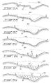
- FIG. 8A to 8M, 9A to 9C and Figure 10 there is shown a simplified block diagram illustrating the working environment generally at 32a delineated by the X and Y trajectory of the contact probe, and in which is located the damaged area 31 to be repaired.
- Associated with the working arm 23 is one or more working tools, and herein three working tools, a gouging tool 33 which is a welding torch (not shown), a grinding tool 34 and a welding tool 35.
- the working end 23 ⁇ of the working arm 23 is provided with a quick connector (not shown) and illustrated by a point 36 which is engageable with quick connectors 37, also illustrated by a point provided on each of the working tools 33 to 35.
- the handle 28 is also herein schematically illustrated and it is also provided with a connector 38 to interconnect with the connector point 36.
- the robot knows precisely the location of these connecting points and is displaced to engage a working tool, effect a work function and replace it to its initial position, and thereafter engage further tools to effect a work operation.
- Figure 9A illustrates the curved surface 11 on which there is located three damaged areas 31.
- the polygonal coordinates of each of those areas are determined, as above described, and the computer calculates a series of passes 39 for the gouging machine 33 to follow to effect the repair of the three damaged areas 31.
- the gouging torch is engaged and gouges the surfaces to the profile as shown in Figure 9C.
- Figure 9A to 9C illustrates the gouging of the damaged cavitated area 31. After the area has been gouged, the working arm then returns the gouging tool 33 to its location and engages the soldering tool 35 to deposit molten metal 31′ within the cavity 31.
- soldering tool effects successive passes to deposit successive layers of solder material 31′ until the entire cavity has been filled.
- the control circuit has predetermined the amount of weld metal to be deposited in the cavity, as it has knowledge of the entire surface area of the working environment, and thus knows the resulting surface profile 40 which should extend over the cavity by interpolation between the undamaged surface.
- weld metal is built up to and beyond this profile 40, and after this operation is effected the working arm then picks up the grinding tool 34 and grinds the top surface to bring it into conformity with the profile 40.
- the grinding operation is illustrated in Figures 8K to 8M.
- FIG. 12A and 12B there is shown a typical construction of the grinding tool 34.
- the tool herein illustrated is a commercial electric or air-powered grinder driving a grinding disc 41.
- the disc is mounted on a suspension mechanism 42 which is controlled by a force sensor 43 to control the grinding.
- Figure 13 illustrates a typical construction of the welding torch 35. It is secured to a linkage 44 to displace the torch along a 90° axis 45. A further linkage 46 displaces the torch 35 along a further 90° axis 47 transverse to the axis 45. The center of rotation of each axis is close to the tip of the welding torch, thus minimizing the translation of the tool end point during any angular adjustment.
- FIG 11 is a block diagram illustrating the entire control system associated with the robotic member 20 of the present invention.
- the control circuit is based on an Intel System 310 Computer with a multi-tasking real time operating system (iRMX86).
- the approach taken to process control is based on a distributed mode of operation using the BITBUS interconnect from Intel.
- the BITBUS 50 is a microcontroller with its own operating system to accomplish a precise task, i.e., for sensor data acquisition and processing, electrode position and feed rate control for the gouging process, adjustment of parameter settings on the welding power supply 51, etc.
- These distributed tasks run continuously and independently of any task running under the operating system of the central computer.
- Communication to the BITBUS network 50 is handled in a master/slave arrangement of circuits 52 associated with the support equipment.
- the robot member 20 is operated by a control unit 53 and motor control circuits 54 connected to the robot member 20 through a power isolated circuit 55.
- a keyboard 56 and a local pendant 58 are associated with the BITBUS microcontroller to provide an interface with an operator. It is not necessary to describe the details of the control circuit as it utilizes off-the-shelf equipment well known to a person skilled in the art, and the arrangement thereof has been clearly illustrated and described.
- the track 13 is shaped to be supported parallel to a curved or flat surface 11 and the robot member 20 together with its working arm 23 and sensor 25 are displaced along the track 13 during operation.
- the working arm and the sensing probe 24 associated therewith are displaced along X and Y coordinates delineating a working environment for the apparatus.
- the sensor tip is displaced in contact with the surface producing signals to the computer of the X, Y and Z coordinates. Any damaged area within the working environment is detected, either automatically or visually by the operator, and a series of coordinate points about the damaged area are selected and stored within the computer.
- the computer calculates the coordinates of a polygonal contour between the points and about the damaged area with reference to a reference plane.
- the work procedure is planned by the computer and the proper tools are selected to effect a gouging, filling and grinding operation to repair the damaged area. It is pointed out that the entire operation is effected in situ so that the operator can maintain a distance from the working tools during work cycles away from any danger.
- the apparatus may be utilized on flat surfaces and may be used to repair all types of damages and imperfections therein.
- the surface may be formed of materials other than metal, such as plastics, and various other tools may be associated with the robotic working arm.
- the entire operation can be automated without the intervention of an operator during the gathering of information on the delineated area and the working cycle of the robotic arm. The only intervention that may be required by an operator is the connection of the track on the object to be investigated and repaired.
Landscapes
- Physics & Mathematics (AREA)
- Engineering & Computer Science (AREA)
- General Physics & Mathematics (AREA)
- Automation & Control Theory (AREA)
- Optics & Photonics (AREA)
- Mechanical Engineering (AREA)
- Manipulator (AREA)
- Finish Polishing, Edge Sharpening, And Grinding By Specific Grinding Devices (AREA)
- Electrical Discharge Machining, Electrochemical Machining, And Combined Machining (AREA)
- Machine Tool Sensing Apparatuses (AREA)
- Image Processing (AREA)
- Length Measuring Devices With Unspecified Measuring Means (AREA)
- Measurement Of Length, Angles, Or The Like Using Electric Or Magnetic Means (AREA)
Claims (31)
- Dispositif pour détecter automatiquement la configuration d'une zone de surface d'un objet et pour y effectuer une fonction d'usinage, ledit dispositif comprenant une piste (13) pouvant être en rapport avec ladite surface (11), un élément de robot actionné par moteur (20) pouvant être relié à ladite piste (13), ledit élément de robot ayant un élément motorisé muni de moyens de couplage avec la piste en engagement avec ladite piste pour déplacer ledit élément de robot à une vitesse prédéterminée et vers une position prédéterminée le long de ladite piste, un bras d'usinage (23) couplé de façon déplaçable audit élément de robot (20), ledit bras d'usinage comportant au moins un outil d'usinage (24) pouvant y être connecté, un circuit de commande (27) associé audit élément de robot (20) pour le déplacer et faire fonctionner ledit bras d'usinage et ledit outil d'usinage, un détecteur (25) relié audit bras d'usinage (23) et comportant un capteur (26) pour détecter une distance qui est mesurée le long d'une verticale à ladite surface ou à toute surface dont ledit circuit de commande (27) a calculé qu'elle est représentative de ladite surface dans un environnement tracé d'usinage pour ledit élément de robot (20) et ledit bras d'usinage (23) ledit détecteur (25) fournissant des données d'information relatives auxdites coordonnées X,Y et Z audit circuit de commande (27) pour déterminer la géométrie de la surface dudit environnement d'usinage et le contour de zones dans ledit environnement d'usinage devant subir une procédure d'usinage par ledit au moins un outil d'usinage (24).
- Dispositif selon la revendication 1, dans lequel ledit bras d'usinage (23) est déplaçable sur ledit axe Y qui est perpendiculaire à l'axe X de déplacement dudit élément de robot (20), ledit détecteur (25) ayant un point de détection orienté vers ladite surface pour fournir des signaux d'information dans l'axe Z par rapport à une série de points de coordonnées autour d'une zone (31), nécessitant un usinage de façon à permettre la détermination du contour et de la forme de ladite zone (31) nécessitant un usinage, par ledit circuit de commande (27) en utilisant les signaux X,Y et Z.
- Dispositif selon la revendication 2, dans lequel ladite surface (11) est une surface de métal courbe, ladite piste (13) étant courbée pour se conformer à la courbure de ladite surface.
- Dispositif selon la revendication 3, dans lequel ladite surface de métal courbe (11) est une partie d'un rail de roulement de turbine hydraulique d'une turbine de génération de puissance, ladite piste (13) étant reliée à ladite surface pour réparer sur place des zones endommagées ou des imperfections à l'intérieur de ladite portion de surface.
- Dispositif selon la revendication 4, dans lequel ledit point de détection est un faisceau de mesure de distance pour détecter la distance entre ledit détecteur (25) et ladite surface (11) dans ledit environnement d'usinage tracé.
- Dispositif selon la revendication 2, dans lequel ledit point de détection est un capteur de contact (26) déplacé en contact avec ladite surface pour détecter la distance entre ledit point de référence dudit bras (23) et ladite surface (11) dans ledit environnement d'usinage tracé, ledit bras comportant une connexion déplaçable pour permettre audit capteur (26) de se déplacer le long de l'axe Z, ledit détecteur (25) comportant une jauge de contrainte pour mesurer ledit déplacement.
- Dispositif selon la revendication 2, dans lequel ledit circuit de commande (27) comporte une fonction de programmation pour déterminer la trajectoire dudit outil (24) au dessus de ladite zone nécessitant l'usinage et le nombre de passage d'un outil d'usinage dans ladite zone.
- Dispositif selon la revendication 7, dans lequel au moins deux outils d'usinage (33,34,35) sont prévus situés à des emplacements prédéterminés par rapport audit élément de robot (20) lesdits outils d'usinage étant sélectionnés et engagés automatiquement par ledit bras d'usinage pour effectuer des fonctions d'usinage contrôlées.
- Dispositif selon la revendication 8, dans lequel ladite surface (11) est une surface métallique, sur laquelle sont prévus un outil formant gouge (33), un outil de soudage (35) et un outil de meulage (34) pour jauger ainsi lesdites zones endommagées et les remplir avec un matériau de soudage au moins jusqu'au profil de surface de ladite surface métallique dans ledit environnement d'usinage et meuler lesdites zones remplies, au niveau de ladite surface dudit environnement d'usinage (32a).
- Dispositif selon la revendication 6, dans lequel ledit bras d'usinage (23) est muni de moyens de manipulation (28) couplés à un détecteur de force (55) pour permettre à un opérateur de le déplacer pour orienter ledit point de détection par rapport aux points de coordonnée autour d'une zone endommagée sélectionnée dans ledit environnement d'usinage (32a) pour établir un contour polygonal de ladite zone endommagée (31) pour y effectuer une fonction d'usinage commandée.
- Dispositif selon la revendication 10, dans lequel ledit circuit de commande (27) comporte une fonction programmée à enseignement automatique et fait fonctionner ledit élément motorisé pour déplacer ledit élément de robot (20) le long de ladite piste (13) pour déterminer la géométrie de ladite piste de telle sorte que ledit élément de commande (27) puisse relier une référence de point d'une extrémité d'outil d'un outil d'usinage à un espace de coordonnées cartésiennes.
- Dispositif selon la revendication 3, dans lequel ladite piste (13) s'étend le long d'un axe rectiligne.
- Dispositif selon la revendication 3, dans lequel ladite surface (11) est une surface métallique, ladite piste (13) étant profilée selon une forme désirée dépendante de la forme de ladite surface, ladite piste (13) étant fixée à un support de piste (14), maintenue au dessus de ladite surface par des pieds de support ajustables (15), lesdits pieds de support étant fixés de façon immobile à ladite surface (11).
- Dispositif selon la revendication 13, dans lequel lesdits pieds de support ajustables (15) sont reliés à rotation audit support de piste (14), lesdits pieds étant ajustables en longueur pour positionner ledit support de piste (14) à une hauteur désirée par rapport à ladite surface (11), de façon à maintenir ledit bras d'usinage (23) parallèle à celle-ci.
- Procédé de détection de façon automatique de la configuration d'une zone de surface et pour effectuer une fonction d'usinage, ledit procédé comprenant les étapes consistant à :(i) relier une piste de support (13) sur une section de ladite zone de surface, ladite piste (13) comportant un élément de robot actionné par un moteur (20) qui lui est relié et équipé d'un bras d'usinage (23) qui lui couplé de façon déplaçable, un détecteur (25) relié audit bras d'usinage, et un circuit de commande (27) associé audit élément de robot (20) ;(ii) déplacer ledit élément de robot (20) et le bras d'usinage (23) respectivement le long de coordonnées X et Y pour tracer un environnement d'usinage (32a) adjacent à ladite piste (13) tout en détectant la distance entre ladite surface (11) et un point de référence dudit bras (23) le long d'une coordonnée Z et produire des signaux de données d'information relatives aux coordonnées X,Y et Z pour stocker des signaux indiquant la configuration de la surface dudit environnement d'usinage ;(iii) détecter des zones de surfaces irrégulières (31), dans ledit environnement d'usinage :(iv) déterminer une série de points de coordonnées autour d'une zone de surface irrégulière détectée pour permettre audit circuit de commande (27 de déterminer un plan de référence basé sur trois desdits points et pour déterminer la projection de tous les points sur ce plan pour fournir le contour polygonal dans ledit plan et stocker des signaux d'information représentatifs de celui-ci ;(v) sélectionner et relier un outil (24) audit bras d'usinage (23) ;(vi) effectuer une fonction d'usinage au moyen dudit outil dans ladite zone polygonale délimitée.
- Procédé selon la revendication 15, dans lequel ladite étape (iv) comporte de plus l'étape consistant à déterminer une série de points de coordonnées à l'intérieur de même qu'à l'extérieur de ladite zone de surface irrégulière de façon à permettre audit circuit de commande (27) de modéliser ladite surface irrégulière et de trouver le profil final désiré après que la fonction d'usinage est achevée.
- Procédé selon la revendication 15, comportant de plus l'étape consistant à positionner au moins deux outils (33,34,35) à des emplacements prédéterminés par rapport à ladite piste (13) et engager automatiquement lesdits outils selon une séquence prédéterminée pour effectuer une série de fonctions d'usinage dans ladite zone polygonale délimitée (31).
- Procédé selon la revendication 17, comportant de plus l'étape consistant à auto-programmer ledit circuit de commande (27) pour effectuer lesdites fonctions d'usinage en analysant lesdits signaux d'information pour détecter la configuration desdites surfaces irrégulières.
- Procédé selon la revendication 15, dans lequel l'étape (ii) comporte une application manuelle d'un capteur de détection (26) reliée audit détecteur (25) en contact avec ledit environnement d'usinage le long desdits axes X,Y et Z pour déterminer sa configuration de surface.
- Procédé selon la revendication 19, dans lequel ladite étape (iii) comporte une détection visuelle desdites zones de surfaces irrégulières.
- Procédé selon la revendication 20, dans lequel l'étape (iv) comporte un déplacement manuel dudit capteur (26) d'une série de points autour d'au moins une zone irrégulière pour fournir des signaux d'information audit circuit de commande (27) pour tracer de façon automatique un contour polygonal.
- Procédé selon la revendication 15, dans lequel lesdites étapes (v) et (vi) sont effectuées séquentiellement avec un outil formant gouge (33), un outil de soudage (35) et un outil de meulage (34) pour nettoyer une surface irrégulière endommagée par cavitation, la remplir avec un matériau de soudage et la meuler jusqu'au niveau de la configuration de surface dudit environnement d'usinage tracé.
- Procédé selon la revendication 22, dans lequel ledit outil formant gouge (33) est commandé pour gouger le métal de ladite surface polygonale délimitée, ledit outil formant gouge étant commandé automatiquement et désexcité lorsque la surface jaugée devient lisse.
- Procédé selon la revendication 22, dans lequel ladite étape consistant à gouger comporte l'étape consistant à enlever une pluralité de couches métalliques successives tout en maintenant l'outil formant gouge (33) à une distance sensiblement constante de la pièce à usiner au moyen d'une commande du courant pour gouger circulant à travers une électrode dudit outil.
- Procédé selon la revendication 23, comportant de plus l'étape consistant à meuler ladite surface polygonale jaugée pour la nettoyer préalablement à son remplissage avec un matériau de soudage puis fournir une cavité préparée adaptée au soudage.
- Procédé selon la revendication 22, dans lequel ladite étape consistant à remplir ladite cavité préparée comporte une application d'une pluralité de couches successives d'un matériau de soudage (31') dans ladite zone de cavité et le maintien de l'outil de soudage (35) a une distance sensiblement constante de la pièce à usiner au moyen d'un contrôle du courant et de la tension de soudage.
- Procédé selon la revendication 22, dans lequel ladite étape de meulage comporte l'application d'une pluralité de passage de meulage successif sur ladite soudure tout en maintenant une force de meulage commandée au moyen du contrôle d'une jauge de contrainte dans ledit détecteur (25).
- Procédé selon la revendication 22 comportant de plus l'étape consistant à détecter ladite zone endommagée polygonale dans ladite zone de surface entre les étapes consistant à gouger, souder et meuler.
- Procédé selon la revendication 15, dans lequel ladite étape (i) comprend un châssis de support de piste (14) pour ladite zone de surface, l'ajustage de sa hauteur et la liaison de ladite piste de support (13) audit châssis de support.
- Procédé selon la revendication 15, dans lequel lesdites étapes (ii) et (iii) sont effectuées en actionnant un élément motorisé équipé de moyens de couplage à la piste (13) et de moyens de déplacement du bras d'usinage (23).
- Procédé selon la revendication 15, dans lequel lesdites étapes (ii) et (vi) sont réalisées automatiquement par ledit circuit de commande (27).
Applications Claiming Priority (2)
| Application Number | Priority Date | Filing Date | Title |
|---|---|---|---|
| US273075 | 1988-11-18 | ||
| US07/273,075 US4959523A (en) | 1988-11-18 | 1988-11-18 | Method and apparatus for automatically sensing the configuration of a surface area and effecting a work function thereon |
Publications (3)
| Publication Number | Publication Date |
|---|---|
| EP0369891A2 EP0369891A2 (fr) | 1990-05-23 |
| EP0369891A3 EP0369891A3 (fr) | 1991-09-04 |
| EP0369891B1 true EP0369891B1 (fr) | 1994-10-05 |
Family
ID=23042442
Family Applications (1)
| Application Number | Title | Priority Date | Filing Date |
|---|---|---|---|
| EP89403177A Expired - Lifetime EP0369891B1 (fr) | 1988-11-18 | 1989-11-17 | Méthode et dispositif pour palper automatiquement la configuration d'une aire de surface et pour y effectuer une opération d'usinage |
Country Status (8)
| Country | Link |
|---|---|
| US (1) | US4959523A (fr) |
| EP (1) | EP0369891B1 (fr) |
| JP (1) | JPH02237726A (fr) |
| AT (1) | ATE112642T1 (fr) |
| BR (1) | BR8905820A (fr) |
| CA (1) | CA2002513C (fr) |
| DE (1) | DE68918670T2 (fr) |
| MX (1) | MX165384B (fr) |
Families Citing this family (55)
| Publication number | Priority date | Publication date | Assignee | Title |
|---|---|---|---|---|
| JP3049442B2 (ja) * | 1990-01-04 | 2000-06-05 | シーアーシー・エヴァンズ、パイプライン、インタナシャナル、インコーパレイティド | 自動溶接作業のための分散処理制御システム |
| ES2120414T3 (es) * | 1991-01-21 | 1998-11-01 | Sulzer Hydro Ag | Metodo de fabricacion de piezas metalicas por un aparato de soldadura, y aparato para su realizacion. |
| AU4026093A (en) * | 1992-04-03 | 1993-11-08 | Foster-Miller Inc. | Method and apparatus for obtaining coordinates describing three-dimensional objects of complex and unique geometry using a sampling probe |
| CA2135620A1 (fr) * | 1992-05-01 | 1993-11-11 | Zev Galel | Procede et installation de decoupage selectif autonome |
| US5811755A (en) * | 1996-01-11 | 1998-09-22 | Lockheed Martin Corp. | Weld repair method for aluminum lithium seam |
| US20020005397A1 (en) * | 1998-04-10 | 2002-01-17 | Bong William L. | Modular welding system and method |
| JP3307886B2 (ja) * | 1998-10-16 | 2002-07-24 | 松下電器産業株式会社 | 溶接装置 |
| AT409731B (de) * | 1998-10-16 | 2002-10-25 | Fronius Schweissmasch Prod | Regelvorrichtung für ein schweissgerät |
| US6560513B2 (en) * | 1999-11-19 | 2003-05-06 | Fanuc Robotics North America | Robotic system with teach pendant |
| FR2806337B1 (fr) * | 2000-03-15 | 2002-05-31 | Joseph Sauron Materiel Ind | Procede et automate de soudage a l'arc utilisant des fils fourres |
| JP2001259839A (ja) * | 2000-03-22 | 2001-09-25 | Matsushita Electric Ind Co Ltd | アーク溶接装置 |
| US6376801B1 (en) * | 2000-10-12 | 2002-04-23 | General Electric Company | Gas turbine component refurbishment apparatus and repair method |
| AT413954B (de) | 2000-11-02 | 2006-07-15 | Fronius Int Gmbh | Erfassungselement für ein schweissgerät |
| US6492618B1 (en) | 2000-11-02 | 2002-12-10 | Tri Tool Inc. | Automatic weld head alignment and guidance system and method |
| ITTO20010294A1 (it) * | 2001-03-29 | 2002-09-29 | Parmaprogetti Srl | Dispositivo per il posizionamento di un organo operatore, ed apparecchiatura saldatrice che ne fa uso. |
| US6944925B2 (en) * | 2001-06-13 | 2005-09-20 | Ttx Company | Articulated connector reconditioning process and apparatuses |
| KR100593535B1 (ko) * | 2001-09-03 | 2006-06-28 | 현대중공업 주식회사 | 각도별 용접조건 자동제어 및 위빙 모션 구현이 가능한자기 진단형 용접 캐리지 제어기 |
| US6548783B1 (en) * | 2001-10-03 | 2003-04-15 | General Electric Company | Apparatus for electric arc overlay welding |
| WO2006057042A1 (fr) * | 2004-11-26 | 2006-06-01 | Shishiai-Kabushikigaisha | Composition de vecteur thermique |
| US8937265B2 (en) * | 2007-02-27 | 2015-01-20 | Illinois Tool Works, Inc. | Welding-type system having a wire feeder system having integrated power source controls and a welding-type power source that is free power parameter selection interfaces |
| US9776274B2 (en) | 2007-10-26 | 2017-10-03 | Ariel Andre Waitzman | Automated welding of moulds and stamping tools |
| US8367962B2 (en) * | 2007-10-26 | 2013-02-05 | Ariel Andre Waitzman | Automated welding of moulds and stamping tools |
| US9292016B2 (en) | 2007-10-26 | 2016-03-22 | Ariel Andre Waitzman | Automated welding of moulds and stamping tools |
| JP4950018B2 (ja) * | 2007-12-25 | 2012-06-13 | アルプス電気株式会社 | 座標入力装置 |
| US20100122973A1 (en) * | 2008-11-20 | 2010-05-20 | General Electric Company | Welding process |
| WO2011102945A2 (fr) * | 2010-02-19 | 2011-08-25 | Dresser-Rand Company | Méplats structuraux soudés sur les carters pour éliminer les buses |
| US8595930B2 (en) * | 2010-03-24 | 2013-12-03 | Dresser-Rand Company | Press-fitting corrosion resistant liners in nozzles and casings |
| FR2970195B1 (fr) * | 2011-01-06 | 2014-01-31 | Ctf France | Automate pour la maintenance de rails et procede de mise en oeuvre |
| GB201103235D0 (en) * | 2011-02-25 | 2011-04-13 | Mirage Machines Ltd | Apparatus,method,system and computer program for machining a workpiece |
| MX351179B (es) * | 2011-08-18 | 2017-10-04 | Victor Equipment Co | Sistema de arco de aire-carbón para detectar y/o reducir irregularidades en una superficie de pieza de trabajo y método para utilizar el mismo. |
| US9097508B2 (en) | 2012-01-25 | 2015-08-04 | Ttx Company | Method for reconditioning a railcar articulated connector |
| US9126287B2 (en) * | 2012-03-12 | 2015-09-08 | Siemens Energy, Inc. | Advanced pass progression for build-up welding |
| US8720526B1 (en) | 2012-11-13 | 2014-05-13 | Siemens Energy, Inc. | Process for forming a long gas turbine engine blade having a main wall with a thin portion near a tip |
| CN103846769A (zh) * | 2012-12-06 | 2014-06-11 | 青岛海尔模具有限公司 | 机器人辅助自适应曲面自动抛光系统 |
| US11767934B2 (en) | 2013-05-23 | 2023-09-26 | Crc-Evans Pipeline International, Inc. | Internally welded pipes |
| US10040141B2 (en) | 2013-05-23 | 2018-08-07 | Crc-Evans Pipeline International, Inc. | Laser controlled internal welding machine for a pipeline |
| US10480862B2 (en) | 2013-05-23 | 2019-11-19 | Crc-Evans Pipeline International, Inc. | Systems and methods for use in welding pipe segments of a pipeline |
| US10589371B2 (en) | 2013-05-23 | 2020-03-17 | Crc-Evans Pipeline International, Inc. | Rotating welding system and methods |
| US9821415B2 (en) | 2014-03-28 | 2017-11-21 | Crc-Evans Pipeline International, Inc. | Internal pipeline cooler |
| US10695876B2 (en) | 2013-05-23 | 2020-06-30 | Crc-Evans Pipeline International, Inc. | Self-powered welding systems and methods |
| US20170259384A1 (en) * | 2014-07-29 | 2017-09-14 | Hydro-Quebec | System and method for robotic thermal treatment by heat induction |
| AU2015308646A1 (en) | 2014-08-29 | 2017-02-09 | Crc-Evans Pipeline International Inc. | Method and system for welding |
| US10065318B2 (en) | 2014-09-15 | 2018-09-04 | The Boeing Company | Methods and systems of repairing a structure |
| US10286553B2 (en) | 2014-09-15 | 2019-05-14 | The Boeing Company | Methods and systems for automatically inspecting an object |
| EP3045394B1 (fr) * | 2015-01-16 | 2020-05-27 | The Boeing Company | Procédé et système de réparation d'une structure |
| AU2016250430B2 (en) * | 2015-10-30 | 2021-07-08 | Ian David McCowat | Method and Apparatus for Refurbishing Shovel Lips |
| US11458571B2 (en) | 2016-07-01 | 2022-10-04 | Crc-Evans Pipeline International, Inc. | Systems and methods for use in welding pipe segments of a pipeline |
| US10226944B2 (en) | 2016-08-30 | 2019-03-12 | The Boeing Company | Adaptable surface treatment repair system |
| US10668577B2 (en) | 2016-09-01 | 2020-06-02 | Crc-Evans Pipeline International Inc. | Cooling ring |
| FR3061053A1 (fr) * | 2016-12-23 | 2018-06-29 | 9349 3039 Quebec Inc | Appareil de reconditionnement de piece lourde et procede |
| US10954001B2 (en) | 2017-02-23 | 2021-03-23 | The Boeing Company | Hanging clamped supports for aircraft |
| US10286460B2 (en) * | 2017-04-07 | 2019-05-14 | Robert J. Murphy | Single-pass, single-radial layer, circumferential-progression fill-welding system, apparatus and method for refurbishing railway and other transit rails |
| CN112139860A (zh) * | 2020-09-22 | 2020-12-29 | 佳奕筱安(上海)机器人科技有限公司 | 基于力控机器人打磨的柔顺轨迹输出方法及其实施装置 |
| CN112917166B (zh) * | 2021-02-04 | 2021-09-07 | 冯剑亮 | 一种机器人脚底板磨纹装置 |
| CN118650564A (zh) * | 2024-07-03 | 2024-09-17 | 浙江大学 | 一种基于视觉定位的曲面板高精度水切割加工系统及其工作方法 |
Family Cites Families (11)
| Publication number | Priority date | Publication date | Assignee | Title |
|---|---|---|---|---|
| JPS55125960A (en) * | 1979-03-12 | 1980-09-29 | Sankyo Seiki Mfg Co Ltd | Automatic working device |
| US4283044A (en) * | 1979-03-23 | 1981-08-11 | Mckibbin John R | Apparatus for guiding a tool along a curved path |
| JPS58208807A (ja) * | 1982-05-31 | 1983-12-05 | Nissan Motor Co Ltd | ロボツトのテイ−チング装置 |
| US4531192A (en) * | 1982-09-23 | 1985-07-23 | Crc Welding Systems, Inc. | Apparatus and method for sensing a workpiece with an electrical arc |
| US4596919A (en) * | 1984-08-23 | 1986-06-24 | Sri International | Three-dimensional imaging device |
| US4716271A (en) * | 1984-09-28 | 1987-12-29 | Welding Services, Inc. | Apparatus for positioning a tool with respect to a cylindrical work piece |
| GB8508391D0 (en) * | 1985-03-30 | 1985-05-09 | Ae Plc | Measurement of engineering components |
| JPS62207580A (ja) * | 1986-03-06 | 1987-09-11 | Kobe Steel Ltd | 偏摩耗した太径長尺ロ−ルの溶接補修方法 |
| US4841123A (en) * | 1987-06-17 | 1989-06-20 | Welding Services, Inc. | Automatic welding device |
| IT1211390B (it) * | 1987-10-06 | 1989-10-18 | Dea Spa | Sistema grafico interattivo per la matematizzazione di modelli fisici |
| DE3907624A1 (de) * | 1988-07-08 | 1990-01-11 | Mtu Maintenance Gmbh | Vorrichtung zum auftragsschweissen der schaufelspitzen von turbinen- und kompressor-schaufeln |
-
1988
- 1988-11-18 US US07/273,075 patent/US4959523A/en not_active Expired - Lifetime
-
1989
- 1989-11-08 CA CA002002513A patent/CA2002513C/fr not_active Expired - Lifetime
- 1989-11-16 MX MX018389A patent/MX165384B/es unknown
- 1989-11-17 AT AT89403177T patent/ATE112642T1/de not_active IP Right Cessation
- 1989-11-17 DE DE68918670T patent/DE68918670T2/de not_active Expired - Fee Related
- 1989-11-17 BR BR898905820A patent/BR8905820A/pt not_active IP Right Cessation
- 1989-11-17 JP JP1299486A patent/JPH02237726A/ja active Pending
- 1989-11-17 EP EP89403177A patent/EP0369891B1/fr not_active Expired - Lifetime
Also Published As
| Publication number | Publication date |
|---|---|
| EP0369891A3 (fr) | 1991-09-04 |
| US4959523A (en) | 1990-09-25 |
| DE68918670D1 (de) | 1994-11-10 |
| JPH02237726A (ja) | 1990-09-20 |
| ATE112642T1 (de) | 1994-10-15 |
| CA2002513C (fr) | 1994-10-11 |
| CA2002513A1 (fr) | 1990-05-18 |
| EP0369891A2 (fr) | 1990-05-23 |
| MX165384B (es) | 1992-11-06 |
| DE68918670T2 (de) | 1995-05-24 |
| BR8905820A (pt) | 1990-06-12 |
Similar Documents
| Publication | Publication Date | Title |
|---|---|---|
| EP0369891B1 (fr) | Méthode et dispositif pour palper automatiquement la configuration d'une aire de surface et pour y effectuer une opération d'usinage | |
| US7123990B2 (en) | Gap welding process | |
| EP3553282B1 (fr) | Système et procédé d'inspection et/ou de réparation d'une ou de plusieurs aubes fixées à un rotor d'un moteur à turbine à gaz à l'aide d'un système robotique | |
| US10449619B2 (en) | System for processing a workpiece | |
| US4590578A (en) | Off-line programmable robot | |
| US6021361A (en) | Robot control system | |
| US4642752A (en) | Programmable automatic manipulator system | |
| KR101268918B1 (ko) | 파이프 플랜지 자동 용접 방법 및 장치 | |
| CN111843505A (zh) | 现场机器人在位测量-铣磨修复一体化工艺方法与系统 | |
| US5347101A (en) | Automatic tracking system for pipeline welding | |
| US20170038760A1 (en) | Machine toolpath compensation using vibration sensing | |
| EP3630404B1 (fr) | Appareil et procede de soudage automatise de couture d 'une piece de travail comprenant une plaque de base ayant un motif de profils elévé. | |
| CN111872850A (zh) | 一种基于焊缝打磨的恒力控制系统 | |
| CN210172874U (zh) | 一种转向架构架自动化焊接系统 | |
| CN107530819A (zh) | 用于将铆钉施加在零件上的包括用于检查并校正铆接操作装置相对于所述零件的位置的装置的设备 | |
| CN212240604U (zh) | 一种基于焊缝打磨的恒力控制装置 | |
| CN115592414A (zh) | 一种用于细长筒类零件的多机器人协同加工装置及方法 | |
| CN111545946B (zh) | 电解铝阳极钢爪高效自动焊接系统及实现方法 | |
| CN119077504B (zh) | 一种基于接触传感的机器人焊缝打磨系统和方法 | |
| CN110154043A (zh) | 基于加工结果进行学习控制的机器人系统及其控制方法 | |
| CN120133808A (zh) | 自动焊接系统及其焊接方法 | |
| CN117400261A (zh) | 一种大型结构件焊缝打磨机器人编程方法、设备及系统 | |
| CN212398554U (zh) | 电解铝阳极钢爪高效自动焊接系统 | |
| CN119772614B (zh) | 复杂异形护栏立柱智能制造方法及系统 | |
| JPH03170283A (ja) | ロボット制御装置 |
Legal Events
| Date | Code | Title | Description |
|---|---|---|---|
| PUAI | Public reference made under article 153(3) epc to a published international application that has entered the european phase |
Free format text: ORIGINAL CODE: 0009012 |
|
| AK | Designated contracting states |
Kind code of ref document: A2 Designated state(s): AT BE CH DE ES FR GB GR IT LI LU NL SE |
|
| PUAL | Search report despatched |
Free format text: ORIGINAL CODE: 0009013 |
|
| AK | Designated contracting states |
Kind code of ref document: A3 Designated state(s): AT BE CH DE ES FR GB GR IT LI LU NL SE |
|
| 17P | Request for examination filed |
Effective date: 19920226 |
|
| 17Q | First examination report despatched |
Effective date: 19940207 |
|
| GRAA | (expected) grant |
Free format text: ORIGINAL CODE: 0009210 |
|
| AK | Designated contracting states |
Kind code of ref document: B1 Designated state(s): AT BE CH DE ES FR GB GR IT LI LU NL SE |
|
| PG25 | Lapsed in a contracting state [announced via postgrant information from national office to epo] |
Ref country code: NL Effective date: 19941005 Ref country code: LI Effective date: 19941005 Ref country code: GR Free format text: LAPSE BECAUSE OF FAILURE TO SUBMIT A TRANSLATION OF THE DESCRIPTION OR TO PAY THE FEE WITHIN THE PRESCRIBED TIME-LIMIT Effective date: 19941005 Ref country code: ES Free format text: THE PATENT HAS BEEN ANNULLED BY A DECISION OF A NATIONAL AUTHORITY Effective date: 19941005 Ref country code: CH Effective date: 19941005 Ref country code: BE Effective date: 19941005 Ref country code: AT Effective date: 19941005 |
|
| REF | Corresponds to: |
Ref document number: 112642 Country of ref document: AT Date of ref document: 19941015 Kind code of ref document: T |
|
| ITF | It: translation for a ep patent filed | ||
| REF | Corresponds to: |
Ref document number: 68918670 Country of ref document: DE Date of ref document: 19941110 |
|
| PG25 | Lapsed in a contracting state [announced via postgrant information from national office to epo] |
Ref country code: LU Free format text: LAPSE BECAUSE OF NON-PAYMENT OF DUE FEES Effective date: 19941130 |
|
| PG25 | Lapsed in a contracting state [announced via postgrant information from national office to epo] |
Ref country code: SE Effective date: 19950105 |
|
| REG | Reference to a national code |
Ref country code: CH Ref legal event code: PL |
|
| ET | Fr: translation filed | ||
| NLV1 | Nl: lapsed or annulled due to failure to fulfill the requirements of art. 29p and 29m of the patents act | ||
| PLBE | No opposition filed within time limit |
Free format text: ORIGINAL CODE: 0009261 |
|
| STAA | Information on the status of an ep patent application or granted ep patent |
Free format text: STATUS: NO OPPOSITION FILED WITHIN TIME LIMIT |
|
| 26N | No opposition filed | ||
| PGFP | Annual fee paid to national office [announced via postgrant information from national office to epo] |
Ref country code: FR Payment date: 19991018 Year of fee payment: 11 |
|
| PGFP | Annual fee paid to national office [announced via postgrant information from national office to epo] |
Ref country code: DE Payment date: 19991028 Year of fee payment: 11 |
|
| PGFP | Annual fee paid to national office [announced via postgrant information from national office to epo] |
Ref country code: GB Payment date: 19991109 Year of fee payment: 11 |
|
| PG25 | Lapsed in a contracting state [announced via postgrant information from national office to epo] |
Ref country code: GB Free format text: LAPSE BECAUSE OF NON-PAYMENT OF DUE FEES Effective date: 20001117 |
|
| GBPC | Gb: european patent ceased through non-payment of renewal fee |
Effective date: 20001117 |
|
| PG25 | Lapsed in a contracting state [announced via postgrant information from national office to epo] |
Ref country code: FR Free format text: LAPSE BECAUSE OF NON-PAYMENT OF DUE FEES Effective date: 20010731 |
|
| PG25 | Lapsed in a contracting state [announced via postgrant information from national office to epo] |
Ref country code: DE Free format text: LAPSE BECAUSE OF NON-PAYMENT OF DUE FEES Effective date: 20010801 |
|
| REG | Reference to a national code |
Ref country code: FR Ref legal event code: ST |
|
| PG25 | Lapsed in a contracting state [announced via postgrant information from national office to epo] |
Ref country code: IT Free format text: LAPSE BECAUSE OF NON-PAYMENT OF DUE FEES Effective date: 20051117 |