EP0369911A1 - Tür für einen kombinierten Bratraum mit einer schwebenden Mikrowellendichtung - Google Patents
Tür für einen kombinierten Bratraum mit einer schwebenden Mikrowellendichtung Download PDFInfo
- Publication number
- EP0369911A1 EP0369911A1 EP89440122A EP89440122A EP0369911A1 EP 0369911 A1 EP0369911 A1 EP 0369911A1 EP 89440122 A EP89440122 A EP 89440122A EP 89440122 A EP89440122 A EP 89440122A EP 0369911 A1 EP0369911 A1 EP 0369911A1
- Authority
- EP
- European Patent Office
- Prior art keywords
- door
- floating
- frame
- cooking
- door according
- Prior art date
- Legal status (The legal status is an assumption and is not a legal conclusion. Google has not performed a legal analysis and makes no representation as to the accuracy of the status listed.)
- Granted
Links
- 238000010411 cooking Methods 0.000 title claims abstract description 18
- 230000002787 reinforcement Effects 0.000 claims description 6
- 238000007789 sealing Methods 0.000 description 5
- 238000000197 pyrolysis Methods 0.000 description 3
- 239000003517 fume Substances 0.000 description 2
- 230000015572 biosynthetic process Effects 0.000 description 1
- 239000000470 constituent Substances 0.000 description 1
- 238000001816 cooling Methods 0.000 description 1
- 238000006073 displacement reaction Methods 0.000 description 1
- 239000011521 glass Substances 0.000 description 1
- 239000004519 grease Substances 0.000 description 1
- 238000010438 heat treatment Methods 0.000 description 1
- 239000002184 metal Substances 0.000 description 1
- 238000011022 operating instruction Methods 0.000 description 1
- 239000000779 smoke Substances 0.000 description 1
Images



Classifications
-
- H—ELECTRICITY
- H05—ELECTRIC TECHNIQUES NOT OTHERWISE PROVIDED FOR
- H05B—ELECTRIC HEATING; ELECTRIC LIGHT SOURCES NOT OTHERWISE PROVIDED FOR; CIRCUIT ARRANGEMENTS FOR ELECTRIC LIGHT SOURCES, IN GENERAL
- H05B6/00—Heating by electric, magnetic or electromagnetic fields
- H05B6/64—Heating using microwaves
- H05B6/76—Prevention of microwave leakage, e.g. door sealings
- H05B6/763—Microwave radiation seals for doors
-
- F—MECHANICAL ENGINEERING; LIGHTING; HEATING; WEAPONS; BLASTING
- F24—HEATING; RANGES; VENTILATING
- F24C—DOMESTIC STOVES OR RANGES ; DETAILS OF DOMESTIC STOVES OR RANGES, OF GENERAL APPLICATION
- F24C15/00—Details
- F24C15/02—Doors specially adapted for stoves or ranges
- F24C15/04—Doors specially adapted for stoves or ranges with transparent panels
Definitions
- the invention relates to a door for a mixed cooking enclosure combining microwave cooking and traditional cooking by electrical resistances, in particular on an improvement made to the wave trap system.
- the doors for mixed enclosures of this type are designed to fulfill the operating conditions specific to each cooking principle.
- doors of this type consist of a monobloc assembly (frames and panes) as on a traditional enclosure, on which is fixed at the periphery, on the one hand a wave trap system as on microwave ovens simple and, on the other hand a door seal as on a traditional enclosure.
- This type of fixed wave trap is active only during the door closing, it is less active as soon as the door comes off the muffle.
- a floating door of this type is composed on the one hand of a door fixed by hinges on the block and on the other hand of a storm door, of smaller dimensions than the door, secured to the door by connections elastic, and mounted on the inside of the door.
- the springs of the elastic connections are crushed and the storm door is regularly applied to the frame of the muffle ensuring sealing against vapors and fumes, whatever the deformations in one or more dimensions of said frame during the phases heating and / or cooling.
- the floating storm door is only active when the door is closed.
- the problem to be solved was therefore: how to maintain a door correctly applied to the enclosure, whatever the deformations of the enclosure due to the temperature (up to 500 ° C in pyrolysis, 300 ° C in cooking).
- the solution currently used is to replace the usual door seal with an active microwave seal.
- the main disadvantage is that the door seal crashes after some time of use, deforms and degrades with heat, and then no longer provides the desired seal, especially on the lower edge of the door where form folds.
- the operating instructions also recommend regular replacement of this door seal after X hours of use.
- the Applicant had the idea of using the principle of the floating door and of separating the wave trap from the door.
- the floating door object of the invention, is formed by a door and a floating part also called a storm door and is characterized in that it is equipped with a wave trap device surrounding the floating storm door .
- the elastic connections between door and storm door consist of flat springs, preferably four, one end of which is fixed, and the other end of which is held by a guide sleeve which can slide in an oblong hole. provided in said end.
- the storm door applies the wave trap and the oven gasket against the muffle, it provides two sealing functions: for vapors and microwaves, knowing that the two cooking modes can be alternated or combined during a given cooking.
- the storm door provides a third function: microwave sealing during the "pre-opening of the door"; the known floating door and the known wave trap being combined in a combination of means.
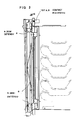
- FIG. 2 shows, in sectional view and closed door, a mixed cooking enclosure (100), traditional and microwave, formed mainly of a muffle (101), and a door floating (102).
- the muffle (101) delimits a muffle cavity (105) whose side walls are equipped with steps (103). On its front face, the muffle (101) has a front edge (106) and an outer edge (104) surrounding the cavity (105).
- the floating door (102) described and shown here is composed of a door (20) and a storm door (2).
- the door (20) is linked to the block (101) by hinges (22), of the conventional type.
- the axis of rotation (26) of the door is here horizontal and in the lower part of the muffle, it could in principle also be vertical to the left or right of the muffle, or else horizontal and in the upper part of the muffle.
- the door (20) mainly consists of an exterior porthole (21) held by springs (27), a handle (23), a door frame (24).
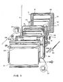
- the door frame (24) is equipped, in its upper part, with a right safety stud (25a) and a left safety stud (25b) ( Figure 1).
- the safety pins (25a, 25b) cooperate with the two micro-contacts (107a, 107b) fixed on the outer edge of the muffle (104). The function of these micro-contacts is to cut the power to the microwave generator when the door is open.
- the inner door (2) consists of an outer inner door frame (4), a door seal frame (5), a wave trap (1) and a trap reinforcement wave (3).
- the outer door frame (4) is formed from a pressed sheet according to the preferred profile visible in FIGS. 5a and 5b.
- the central area (4a) of the frame (4) is perforated in a known manner, to form a microwave screen and allow visibility through the floating door (102).
- the wave trap (1) and its reinforcement (3) are of conventional design, and are fixed to the outer door frame (4).
- An internal window (12) having the function of protecting the central zone (4a) perforated against grease splashes is held by pinching between said central zone (4a) perforated and the edge (3a) of the reinforcement.
- the groove (4b) completely surrounds the perforated area (4a) of the frame (4).
- Another frame called pyrolytic frame (5) has the function of maintaining and positioning a door seal (10).
- the door seal (10) is a glass silk braid, not active in the microwave, like that used on simple traditional enclosures, its function is the usual function of sealing against vapors and fumes during cooking and the pyrolysis.
- the frame (5) has a flat fixing edge (5a) and a groove (5b) for pinching the inner edge of the door seal (10) against the outer frame (4), so that the braid of the seal door (10) is held flat against the outer flat edge of the frame (4).
- the seal (10) completely covers three of the edges of the frame (4), and partially covers the lower horizontal edge of said frame (4), to avoid the formation of folds by closing the door.
- the frame (5) is fixed by its edge (5a) over the entire periphery of the frame (4) by means of rivets for example.
- the storm door (2) is linked to the door (20) by elastic connections such as guided springs.
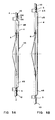
- the springs are flat springs (8) shown in detail in Figures 6a and 6b.
- Each flat spring in sheet metal has a flat central part (8c), two arms (8b) on either side of the central part (8c), each arm (8b) ending in one end (8a).
- One end (8a) and the middle part (8c) have a hole for fixing, the other end (8a) has an oblong hole (8d) intended to cooperate with a guide bush (9).
- the length of the oblong hole (8d) is a function of the length of the displacement of the middle part (8c), between the closed and open positions of the floating door (102).
- the springs (8) are four in number, arranged between the door frame (24) and the outer door frame (4), and distributed on each side of the frame (4), between the groove (4b) and the edge of the frame (4) as shown in Figure 1.
- the guide sleeve (9) and the ends of the arms (8a) are fixed to the frame (4), the middle part (8c) being fixed to the frame (24).
- An intermediate window (11) is held between the two frames (4) and (24), it serves as a heat shield, in particular during the pyrolysis operations.
- the floating storm door ensures both vapor and smoke tightness and microwave tightness whatever the relative deformations of the muffle due to the temperature.
- pre-opening a first step called "pre-opening" (see Figure 3) during which the pins (25a and 25b) are not yet released from the micro-contacts (107a, 107b), but during which the counter door is applied against the block under the action of the half-relaxed springs (8).
- the wave trap therefore remains active even if the door (20) is detached from the edge of the muffle, the wave generator not yet being cut.
- the deflection of the springs (8) is of the order of 10 mm.
Landscapes
- Engineering & Computer Science (AREA)
- Chemical & Material Sciences (AREA)
- Combustion & Propulsion (AREA)
- Mechanical Engineering (AREA)
- General Engineering & Computer Science (AREA)
- Physics & Mathematics (AREA)
- Electromagnetism (AREA)
- Electric Ovens (AREA)
Applications Claiming Priority (2)
| Application Number | Priority Date | Filing Date | Title |
|---|---|---|---|
| FR8815213 | 1988-11-17 | ||
| FR8815213A FR2639170B1 (fr) | 1988-11-17 | 1988-11-17 | Porte pour enceinte de cuisson mixte comportant un piege a ondes flottant |
Publications (2)
| Publication Number | Publication Date |
|---|---|
| EP0369911A1 true EP0369911A1 (de) | 1990-05-23 |
| EP0369911B1 EP0369911B1 (de) | 1994-03-30 |
Family
ID=9372119
Family Applications (1)
| Application Number | Title | Priority Date | Filing Date |
|---|---|---|---|
| EP19890440122 Expired - Lifetime EP0369911B1 (de) | 1988-11-17 | 1989-11-16 | Tür für einen kombinierten Bratraum mit einer schwebenden Mikrowellendichtung |
Country Status (3)
| Country | Link |
|---|---|
| EP (1) | EP0369911B1 (de) |
| DE (1) | DE68914253T2 (de) |
| FR (1) | FR2639170B1 (de) |
Cited By (4)
| Publication number | Priority date | Publication date | Assignee | Title |
|---|---|---|---|---|
| CN1299065C (zh) * | 2002-07-12 | 2007-02-07 | 乐金电子(天津)电器有限公司 | 微波炉的弹簧锁装置 |
| KR100698212B1 (ko) | 2005-05-20 | 2007-03-22 | 엘지전자 주식회사 | 전기 오븐 레인지용 오븐 도어 |
| EP2469178A1 (de) * | 2010-12-23 | 2012-06-27 | BSH Bosch und Siemens Hausgeräte GmbH | Garbehandlungsofen |
| EP2480048A1 (de) * | 2010-12-23 | 2012-07-25 | BSH Bosch und Siemens Hausgeräte GmbH | Hochfrequenzgargerät |
Families Citing this family (1)
| Publication number | Priority date | Publication date | Assignee | Title |
|---|---|---|---|---|
| DE10208042B4 (de) * | 2002-02-25 | 2016-09-01 | BSH Hausgeräte GmbH | Türgriff |
Citations (10)
| Publication number | Priority date | Publication date | Assignee | Title |
|---|---|---|---|---|
| GB778878A (en) * | 1955-04-24 | 1957-07-10 | Revo Electric Company Ltd | Oven, refrigerator and like doors |
| US2860026A (en) * | 1956-03-08 | 1958-11-11 | Gen Motors Corp | Domestic appliance |
| DE1906621B1 (de) * | 1969-02-11 | 1970-09-03 | Licentia Gmbh | Bratraumtuere fuer Kuechenherde |
| US3666904A (en) * | 1971-04-12 | 1972-05-30 | Bowmar Tic Inc | Microwave oven and door structure for minimizing leakage |
| DE2102015A1 (de) * | 1971-01-16 | 1972-07-27 | Burger Eisenwerke Ag | Bratraumtüre für Herde, insbesondere für Herde mit Selbstreinigung |
| US3808391A (en) * | 1973-01-29 | 1974-04-30 | Hobart Mfg Co | Microwave oven door assembly |
| US4013861A (en) * | 1975-08-13 | 1977-03-22 | The Frymaster Corporation | Microwave oven door seal |
| FR2399780A1 (fr) * | 1977-08-01 | 1979-03-02 | Bosch Siemens Hausgeraete | Four a micro-ondes comportant une porte du type a tiroir |
| CH633413A5 (en) * | 1978-11-08 | 1982-12-15 | Prometheus Ag Fabrik Elektrisc | Oven door with inspection window |
| EP0121893A2 (de) * | 1983-04-07 | 1984-10-17 | INDUSTRIE ZANUSSI S.p.A. | Tür für einen Gas- oder Elektro- und Mikrowellenkombinationsofen |
-
1988
- 1988-11-17 FR FR8815213A patent/FR2639170B1/fr not_active Expired - Fee Related
-
1989
- 1989-11-16 DE DE1989614253 patent/DE68914253T2/de not_active Expired - Fee Related
- 1989-11-16 EP EP19890440122 patent/EP0369911B1/de not_active Expired - Lifetime
Patent Citations (10)
| Publication number | Priority date | Publication date | Assignee | Title |
|---|---|---|---|---|
| GB778878A (en) * | 1955-04-24 | 1957-07-10 | Revo Electric Company Ltd | Oven, refrigerator and like doors |
| US2860026A (en) * | 1956-03-08 | 1958-11-11 | Gen Motors Corp | Domestic appliance |
| DE1906621B1 (de) * | 1969-02-11 | 1970-09-03 | Licentia Gmbh | Bratraumtuere fuer Kuechenherde |
| DE2102015A1 (de) * | 1971-01-16 | 1972-07-27 | Burger Eisenwerke Ag | Bratraumtüre für Herde, insbesondere für Herde mit Selbstreinigung |
| US3666904A (en) * | 1971-04-12 | 1972-05-30 | Bowmar Tic Inc | Microwave oven and door structure for minimizing leakage |
| US3808391A (en) * | 1973-01-29 | 1974-04-30 | Hobart Mfg Co | Microwave oven door assembly |
| US4013861A (en) * | 1975-08-13 | 1977-03-22 | The Frymaster Corporation | Microwave oven door seal |
| FR2399780A1 (fr) * | 1977-08-01 | 1979-03-02 | Bosch Siemens Hausgeraete | Four a micro-ondes comportant une porte du type a tiroir |
| CH633413A5 (en) * | 1978-11-08 | 1982-12-15 | Prometheus Ag Fabrik Elektrisc | Oven door with inspection window |
| EP0121893A2 (de) * | 1983-04-07 | 1984-10-17 | INDUSTRIE ZANUSSI S.p.A. | Tür für einen Gas- oder Elektro- und Mikrowellenkombinationsofen |
Cited By (4)
| Publication number | Priority date | Publication date | Assignee | Title |
|---|---|---|---|---|
| CN1299065C (zh) * | 2002-07-12 | 2007-02-07 | 乐金电子(天津)电器有限公司 | 微波炉的弹簧锁装置 |
| KR100698212B1 (ko) | 2005-05-20 | 2007-03-22 | 엘지전자 주식회사 | 전기 오븐 레인지용 오븐 도어 |
| EP2469178A1 (de) * | 2010-12-23 | 2012-06-27 | BSH Bosch und Siemens Hausgeräte GmbH | Garbehandlungsofen |
| EP2480048A1 (de) * | 2010-12-23 | 2012-07-25 | BSH Bosch und Siemens Hausgeräte GmbH | Hochfrequenzgargerät |
Also Published As
| Publication number | Publication date |
|---|---|
| DE68914253D1 (de) | 1994-05-05 |
| FR2639170B1 (fr) | 1991-01-11 |
| FR2639170A1 (fr) | 1990-05-18 |
| EP0369911B1 (de) | 1994-03-30 |
| DE68914253T2 (de) | 1994-10-06 |
Similar Documents
| Publication | Publication Date | Title |
|---|---|---|
| EP0061970B1 (de) | Schiebefenster mit elektrischer Steuerung und Näherungsdetektor | |
| BE1004250A5 (fr) | Charniere de chassis de fenetre a battants. | |
| EP0369911B1 (de) | Tür für einen kombinierten Bratraum mit einer schwebenden Mikrowellendichtung | |
| FR2705765A1 (fr) | Porte de four. | |
| EP3184910A1 (de) | Tür für garraum mit entfernbarer innenplatte | |
| FR2670563A1 (fr) | Porte pour four de cuisson a usage domestique. | |
| EP0149385B1 (de) | Montageeinrichtung für ein Schauglas einer Ofentür | |
| FR2812074A1 (fr) | Porte isolante en verre pour une chambre de cuisson d'un appareil de cuisson | |
| EP1400195B1 (de) | Haushaltsgerät aus scharnierartig verbundenen Rostelementen | |
| EP3840151B1 (de) | Schaltkasten und zugehörige elektrische ausrüstung | |
| FR2853955A1 (fr) | Dispositif de supportage d'un moufle de four de cuisson | |
| EP0202144A1 (de) | Elektromagnetische Abdichtungsvorrichtung durch eine messerförmige Kontaktfeder | |
| EP1048902A1 (de) | Backofen mit gekühlter Tür | |
| EP0651122B1 (de) | Verbesserung an Scharnieren zur gelenkigen Verbindung eines Flügels an einem Rahmen | |
| EP0621388B1 (de) | Tür mit Stangenverschluss mit verbessertem Schlosseinbau | |
| FR2653211A1 (fr) | Porte pour four de cuisson d'aliments et four equipe d'une telle porte. | |
| NO165394B (no) | Fremgangsmaate til fremstilling av fettsyrenitriler og glyserol fra glyserider. | |
| EP4346036B1 (de) | Schutzzubehör für die tür eines schaltschranks, tür und schaltschrank mit solchem schutzzubehör | |
| EP1553257B1 (de) | Panzertür oder -fenster mit einer direkt an der Panzerplatte verbundenen Verglasung | |
| FR2559965A1 (fr) | Dispositif de connexion entre une gaine de protection et de blindage de cables electriques et l'enveloppe conductrice d'un appareil, par exemple dans un ordinateur | |
| FR2737052A1 (fr) | Dispositif de jumelage pour coffrets pour appareillages electriques | |
| FR2756616A1 (fr) | Porte pour une enceinte a cuire et a rotir d'un four | |
| FR2723488A1 (fr) | Dispositif de commande pour materiel electrique antideflagrant, et enceinte ou enveloppe dite "a securite augmentee" equipee d'un tel dispositif de commande | |
| JPH04187124A (ja) | グリラー | |
| FR2785660A1 (fr) | Joint refractaire resilient hermetique et dispositif de fermeture pour un foyer de cheminee le mettant en oeuvre |
Legal Events
| Date | Code | Title | Description |
|---|---|---|---|
| PUAI | Public reference made under article 153(3) epc to a published international application that has entered the european phase |
Free format text: ORIGINAL CODE: 0009012 |
|
| AK | Designated contracting states |
Kind code of ref document: A1 Designated state(s): DE GB |
|
| 17P | Request for examination filed |
Effective date: 19900612 |
|
| RAP1 | Party data changed (applicant data changed or rights of an application transferred) |
Owner name: DE DIETRICH EQUIPEMENT MENAGER, SOCIETE ANONYME |
|
| RAP1 | Party data changed (applicant data changed or rights of an application transferred) |
Owner name: DE DIETRICH EUROPEENNE D'ELECTROMENAGER |
|
| 17Q | First examination report despatched |
Effective date: 19930602 |
|
| GRAA | (expected) grant |
Free format text: ORIGINAL CODE: 0009210 |
|
| AK | Designated contracting states |
Kind code of ref document: B1 Designated state(s): DE GB |
|
| REF | Corresponds to: |
Ref document number: 68914253 Country of ref document: DE Date of ref document: 19940505 |
|
| GBT | Gb: translation of ep patent filed (gb section 77(6)(a)/1977) |
Effective date: 19940629 |
|
| PGFP | Annual fee paid to national office [announced via postgrant information from national office to epo] |
Ref country code: GB Payment date: 19941024 Year of fee payment: 6 |
|
| PGFP | Annual fee paid to national office [announced via postgrant information from national office to epo] |
Ref country code: DE Payment date: 19941025 Year of fee payment: 6 |
|
| PLBE | No opposition filed within time limit |
Free format text: ORIGINAL CODE: 0009261 |
|
| STAA | Information on the status of an ep patent application or granted ep patent |
Free format text: STATUS: NO OPPOSITION FILED WITHIN TIME LIMIT |
|
| 26N | No opposition filed | ||
| PG25 | Lapsed in a contracting state [announced via postgrant information from national office to epo] |
Ref country code: GB Effective date: 19951116 |
|
| GBPC | Gb: european patent ceased through non-payment of renewal fee |
Effective date: 19951116 |
|
| PG25 | Lapsed in a contracting state [announced via postgrant information from national office to epo] |
Ref country code: DE Effective date: 19960801 |