EP4346036B1 - Schutzzubehör für die tür eines schaltschranks, tür und schaltschrank mit solchem schutzzubehör - Google Patents
Schutzzubehör für die tür eines schaltschranks, tür und schaltschrank mit solchem schutzzubehör Download PDFInfo
- Publication number
- EP4346036B1 EP4346036B1 EP23199776.8A EP23199776A EP4346036B1 EP 4346036 B1 EP4346036 B1 EP 4346036B1 EP 23199776 A EP23199776 A EP 23199776A EP 4346036 B1 EP4346036 B1 EP 4346036B1
- Authority
- EP
- European Patent Office
- Prior art keywords
- flap
- border
- opening
- door
- protection
- Prior art date
- Legal status (The legal status is an assumption and is not a legal conclusion. Google has not performed a legal analysis and makes no representation as to the accuracy of the status listed.)
- Active
Links
Images


Classifications
-
- H—ELECTRICITY
- H02—GENERATION; CONVERSION OR DISTRIBUTION OF ELECTRIC POWER
- H02B—BOARDS, SUBSTATIONS OR SWITCHING ARRANGEMENTS FOR THE SUPPLY OR DISTRIBUTION OF ELECTRIC POWER
- H02B1/00—Frameworks, boards, panels, desks, casings; Details of substations or switching arrangements
- H02B1/26—Casings; Parts thereof or accessories therefor
- H02B1/30—Cabinet-type casings; Parts thereof or accessories therefor
- H02B1/38—Hinged covers or doors
-
- H—ELECTRICITY
- H02—GENERATION; CONVERSION OR DISTRIBUTION OF ELECTRIC POWER
- H02B—BOARDS, SUBSTATIONS OR SWITCHING ARRANGEMENTS FOR THE SUPPLY OR DISTRIBUTION OF ELECTRIC POWER
- H02B1/00—Frameworks, boards, panels, desks, casings; Details of substations or switching arrangements
- H02B1/26—Casings; Parts thereof or accessories therefor
- H02B1/30—Cabinet-type casings; Parts thereof or accessories therefor
- H02B1/306—Accessories, e.g. windows
Definitions
- the present invention relates to the field of protective accessories for electrical cabinet doors, the field of electrical cabinet doors and the field of electrical cabinets.
- electrical protection devices such as circuit breakers
- circuit breakers are known, which are installed in electrical cabinets that can be closed by a door.
- Such electrical protection devices may in certain situations require direct access through the door of the electrical cabinet, while ensuring protection, for example, with an IP3X protection rating of these electrical protection devices.
- a protective accessory comprising a frame fitted with a rubber seal which provides IP3X protection around the electrical protection device.
- US 3,075,061 A , EP 0 387 973 A1 And US 9 461 446 B1 disclose examples of such arrangements.
- Such protective electrical equipment can be either fixed or withdrawable.
- withdrawable protective electrical equipment is known to be able to adopt several positions relative to its chassis in addition to the connected position corresponding to the fixed position of fixed protective electrical equipment, in which the power part of the protective electrical equipment is retracted inside the chassis.
- withdrawable protective electrical equipment can also adopt a disconnected position, in which the power part of the protective electrical equipment projects from the chassis.
- the present invention aims to overcome at least one of these drawbacks and to propose a solution which makes it possible to guarantee protection preferably with an IP3X rating around the protective electrical equipment whatever the position of the latter in its chassis, and which allows the opening and closing of the door of the electrical cabinet integrating the protective accessory whatever the position of the protective electrical equipment in its chassis.
- the invention also relates to a door for an electrical cabinet comprising a window configured to form a passage of a front face of an electrical protection device, characterized in that the door comprises said protection accessory according to the invention and in that the frame is mounted on the window.
- the invention also relates to an electrical cabinet comprising the door movable in rotation around a pivot axis between a closed position and an open position, characterized in that said door is according to the invention.
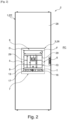
- the invention relates to a protective accessory for door 1 of electrical cabinet 2.
- an electrical protection device D comprises a chassis C which is intended to be fixed in the electrical cabinet 2 and a power part with a front face F, which power part can be received in the chassis C.
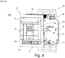
- the power part of the protective electrical equipment D is mobile relative to the chassis C between a PC connected position ( Figure 7 ), in which the power part is received entirely in the chassis C and a disconnected position PD ( figure 8 ), in which the power part is partially received in the chassis C.
- the disconnected position PD the front face F protrudes more from the chassis C than in the connected position PC.
- the power part and the chassis C are fixed in the electrical cabinet 2.
- the first flap 9 and the second flap 10 firstly make it possible to guarantee protection, preferably with an IP3X rating, by forming a barrier which prevents access to the protective electrical equipment D, at least via two lateral edges B of the front face F, when the protective electrical equipment D is removable and is in the connected position PC and the door 1 of the electrical cabinet 2 is in the closed position PF, as illustrated by figures 1 , 2 And 7 or when the protective electrical apparatus D is withdrawable and is in the disconnected position PD and the door 1 of the electrical cabinet 2 is in the closed position PF, as illustrated in figure 8 or when the protective electrical equipment D is fixed (not shown) and the door 1 of the electrical cabinet 2 is in the closed position PF.
- first return member 11 and the second return member 12 respectively make it possible to permanently return the first flap 9 and second flap 10 to their initial position PI in order to guarantee that the first flap 9 and second flap 10 remain in contact with the lateral edges B of the front face F of the electrical protection apparatus D and thus to guarantee protection preferably with an IP3X index.
- first flap 9 and the second flap 10 also allow the opening and closing of the door 1 regardless of the position of the withdrawable electrical protection device D relative to its chassis C, that is to say both in the connected position PC which is illustrated in Figure 12 , than in the disconnected PD position which is illustrated in figures 13 And 14 .
- the front face F protrudes more into the main opening 4 than in the connected position PC, there is a passage critical to overcome which is visible at the Figure 14 when opening or closing the door 1.
- the first flap 9 and the second flap 10 can pivot, the passage of the front face F through the main opening 4 is not hindered by the first flap 9 and the second flap 10 and is therefore done without any blockage.
- Detail Z of the figures 14 And 15 more particularly illustrates the ability of the second flap 10 to pivot to allow the front face F to pass through the main opening 4 under these conditions.
- this protective accessory solution according to the invention with the first flap 9 and the second flap 10 also makes it possible to compensate for the positioning defects of the protective electrical apparatus D in the electrical cabinet 2, which leads to simplifying the mounting of the chassis C of the protective electrical apparatus D in the electrical cabinet 2, which no longer has to be as precise as in the prior art.
- the frame 3 is a single piece, preferably obtained by molding.
- the frame 3 is preferably made of a polymer material such as plastic. This material is preferably rigid, but this example is not limiting and the material can also be flexible.
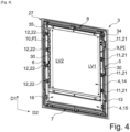
- the frame 3 preferably comprises a front interface 26 and a mounting interface 27 arranged opposite the front interface 26.
- the mounting interface 27 is intended to be mounted on the door 1, without being visible from the outer face 28 of the door 1, while the front interface 26 is visible on the outer face 28.
- the front interface 26 is preferably smooth and the mounting interface 27 is preferably ribbed.
- the main opening 4 is preferably rectangular in shape.
- the first, second, third, fourth edges 5, 6, 7, 8 each preferably have a rectangular section.
- the first flap 9 and the second flap 10 each have an essentially flat and rectangular shape.
- the first flap 9 and the second flap 10 each have a first face 29 which is smooth and on the side of the front interface 26 and a second face 30 which is ribbed and on the side of the mounting interface 27.
- the initial position PI of the first flap 9 preferably corresponds to a position of the first flap 9 in which the latter conceals a portion of the main opening 4 near the first border 5.
- the maximum opening position of the first flap 9 preferably corresponds to a position of the first flap 9 in which the latter comes into abutment against the thickness of the first border 5.
- the initial position PI of the second flap 10 preferably corresponds to a position of the second flap 10 in which the latter conceals a portion of the main opening 4 near the second border 6.
- the maximum opening position of the second flap 10 preferably corresponds to a position of the second flap 10 in which the latter comes into abutment against the thickness of the second border 6.
- a first subassembly formed by the first return member 11 and the first flap 9 is preferably mounted on the mounting interface 27 by first fixing means.
- the first flap 9 is mounted on the mounting interface 27 in particular by a first pivot connection.
- the second subassembly formed by the second return member 12 and the second flap 10 is preferably mounted on the mounting interface 27 by second fixing means.
- the second flap 10 is mounted on the mounting interface 27 in particular by a second pivot connection.
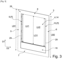
- said protective accessory further comprises a separating spacer 13 connecting the first edge 5 and the second edge 6 and extending longitudinally in the second direction D2, said separating spacer 13 being configured to separate the main opening 4 in two, into a first opening 14 and a second opening 15.
- the separating spacer 13 makes it possible to divide the main opening 4 into two openings, namely a first opening 14 and a second opening 15.
- the front face F can pass through the first opening 14 between the connected position PC, as shown in Figure 7 , and the disconnected PD position, as shown in the figure 8 .
- the interface I of position control is accessible from the second opening 15 and remains fixed relative to the chassis C.
- the electrical protection apparatus D is fixed and according to an example not illustrated, then the front face F is accessible through the first opening 14 and remains fixed relative to the chassis C.
- the first flap 9 conceals a portion of the first opening 14 near the first border 5 and the second flap 10 conceals a portion of the first opening 14 near the second border 6.
- the third flap 17 described below conceals a portion of the second opening 15 near the first border 5 and the fourth flap 18 described below conceals a portion of the second opening 15 near the second border 6.
- the separating spacer 13 has a rectangular section.
- the first opening 14 has a shape suitable and intended to surround with clearance the front face F of the electrical protection apparatus D and is preferably rectangular in shape.
- the first flap 9 and the second flap 10 make it possible to cover this clearance at the level of the lateral edges B of the front face F.
- the dimensions of the first flap 9 and the second flap 10, and in particular their width, can be adapted and modified according to the dimensions of the clearance to be covered which can also vary according in particular to the dimensions of the electrical protection equipment D.
- the second opening 15 has a shape suitable and intended to surround with clearance the interface I for controlling the position of the electrical protection apparatus D and is preferably rectangular in shape.
- the third flap 17 and the fourth flap 18 described below make it possible to cover this clearance at the level of the lateral edges of the position control interface I.
- the first opening 14 is preferably larger than the second opening 15.
- the first flap 9 has a first length LV1 less than a length LB1 of the first border 5 and the second flap 10 has a second length LV2 less than a length LB2 of the second border 6 and the first flap 9 and the second flap 10 project into the first opening 14.
- the protective accessory comprises only two flaps, namely the first flap 9 and the second flap 10 which protrude into the first opening 14.
- This variant embodiment is suitable for fixed electrical protection equipment D according to the second possibility.
- the second opening 15 is closed by a shutter 16.
- the shutter 16 makes it possible to cover at least the second opening 15 which is not useful, because the electrical protection apparatus D does not have an interface I for controlling the position in this case.
- the shutter 16 makes it possible to cover both the second opening 15 and the separation spacer 13.
- the shutter 16 preferably has an essentially flat and rectangular shape.
- the shutter 16 can be fixed to the frame 3 by fixing means, for example of the interlocking or clipping type.
- the first length LV1 of the first shutter 9 and the second length LV2 of the second shutter 10 are equal to a length LO1 of the first opening 14.
- the protective accessory comprises a total of four flaps, namely the first flap 9 and the second flap 10 which project into the first opening 14 and the third flap 17 and the fourth flap 18 which project into the second opening 15.
- This variant embodiment is suitable for a removable protective electrical device D according to the first possibility.
- the third flap 17 and the fourth flap 18 each have, for example, an essentially flat and rectangular shape.
- the third flap 17 and the fourth flap 18 each have a first face 29 which is smooth and on the side of the front interface 26 and a second face 30 which is ribbed and on the side of the mounting interface 27.
- the width of the third flap 17 and the width of the fourth flap 18 may be equal to or different from the width of the first flap 9 and the width of the second flap 10 respectively.
- the initial position PI of the third flap 17 preferably corresponds to a position of the third flap 17 in which the latter conceals a portion of the second opening 15 near the first border 5.
- the initial position PI of the fourth flap 18 preferably corresponds to a position of the fourth flap 18 in which the latter conceals a portion of the second opening 15 near the second border 6.
- a third sub-assembly formed by the third return member 19 and the third flap 17 is preferably mounted on the mounting interface 27 by third fixing means.
- the third flap 17 is mounted on the mounting interface 27 in particular by a third pivot connection 31.
- the fourth subassembly formed by the fourth return member 20 and the fourth flap 18 is preferably mounted on the mounting interface 27 by fourth fixing means.
- the fourth flap 18 is mounted on the mounting interface 27 in particular by a fourth pivot connection.
- the third panel 17 is preferably a mirror image of the fourth panel 18.
- the third flap 17 may be marked with a first marking 32 on its second face 30, which consists for example of at least one symbol, such as the letter R.
- the fourth flap 18 may be marked with a second marking 33 on its second face 30, which consists for example of at least one symbol, such as the letter L.
- the third flap 17 has a third length LV3 less than the length LB1 of the first border 5 and the first length LV1 of the first flap 9 and the fourth flap 18 has a fourth length LV4 less than the length LB2 of the second border 6 and the second length LV2 of the second flap 10 and the third flap 17 and the fourth flap 18 project into the second opening 15.
- the first length LV1 of the first flap 9 and the second length LV2 of the second flap 10 are equal to a length LO1 of the first opening 14 and the third length LV3 of the third flap 17 and the fourth length LV4 of the fourth flap 18 are equal to a length LO2 of the second opening 15.
- the first return member 11 and the second return member 12 respectively comprise at least one first leaf spring 21 associated with at least one first cam of the first flap 9 and at least one second leaf spring 22 associated with at least one second cam.
- said at least one first leaf spring 21 and said at least one second leaf spring 22 respectively make it possible to permanently return the first flap 9 and second flap 10 to their initial position PI in order to guarantee that the first flap 9 and second flap 10 remain in contact with the lateral edges B of the front face F of the electrical protection apparatus D and thus guarantee protection of index IP3X.
- said at least one first leaf spring 21 and said at least one second leaf spring 22 are made of metal, preferably steel.
- the first return member 11 comprises four first leaf springs 21 which are distributed uniformly over the first length LV1 of the first flap 9 and the second return member 12 comprises four second leaf springs 22 which are distributed equidistantly over the second length LV2 of the second flap 10.
- the third return member 19 and the fourth return member 20 respectively comprise at least one third leaf spring 23 associated with at least one third cam 25 and at least one fourth leaf spring 24 associated with at least one fourth cam.
- said at least one third leaf spring 23 and said at least one fourth leaf spring 24 respectively make it possible to permanently return the third flap 17 and the fourth flap 18 to their initial position PI in order to guarantee that the third flap 17 and the fourth flap 18 remain in contact with the lateral edges of the interface I of the protective electrical apparatus D and thus guarantee protection of index IP3X.
- said at least one third leaf spring 23 and said at least one fourth leaf spring 24 are made of metal, preferably steel.
- the third return member 19 comprises a single third leaf spring 23 which is located substantially in the middle of the third length LV3 of the third flap 17 and the fourth return member 20 preferably comprises a single fourth leaf spring 24 which is located substantially in the middle of the fourth length LV4 of the fourth flap 18.
- a first metal strip 34 comprises the first four leaf springs 21 and the third leaf spring 23.
- the first metal strip 34 may comprise five equidistant tabs, for example obtained by cutting and forming the first four leaf springs 21 and the third leaf spring 23.
- the first metal strip 34 is preferably secured to the mounting interface 27 at the first edge 5 by five sets of fastening means.
- such a set of fixing means comprises for example two screws 36 which can be screwed through two orifices 37 located on either side of the tab and two holes 38 provided in the mounting interface 27 at the level of the first edge 5.
- a second metal strip 35 comprises the four second leaf springs 22 and the fourth leaf spring 24.
- the second metal strip 35 can comprise five equidistant tabs, for example obtained by cutting and forming the four second leaf springs 22 and the fourth leaf spring 24.
- the second metal strip 35 is preferably fixed to the mounting interface 27 at the second edge 6 by five sets of fixing means.
- a set of fixing means comprises, for example, two screws 36 which can be screwed through two orifices 37 located on either side of the tab and two holes 38 provided in the mounting interface 27 at the second edge 6.
- the third edge 7 and the fourth edge 8 may each be provided with a sealing gasket which extends over their length, for example made of rubber, which projects respectively into the second opening 15 and into the first opening 14.
- the separating spacer 13 may be provided with two sealing gaskets which extend over its length, for example made of rubber, and which project respectively into the first opening 14 and into the second opening 15.
- This configuration guarantees protection preferably with an IP 3X rating around the entire perimeter of the front face F of the electrical equipment. protection D and where appropriate around the entire perimeter of the position control interface I.
- the invention relates to a door 1 for an electrical cabinet comprising a window configured to form a passage of a front face F of an electrical protection device D.
- the door 1 comprises said protective accessory according to the invention and as described previously and the frame 3 is mounted on the window.
- the invention relates to an electrical cabinet 2 comprising the door 1 movable in rotation about a pivot axis AP between a closed position PF and an open position PO.
- said electrical cabinet 2 is characterized in that said door 1 is according to the invention and as described previously.
- the invention relates to an assembly comprising the electrical cabinet 2 comprising said protection accessory and said electrical protection apparatus D, said electrical protection apparatus D comprising a chassis C and a power part comprising a front face F, which power part is suitable and intended to be received in the chassis C, while being movable relative to the chassis C between a connected position PC and a disconnected position PD.
- the electrical protection device D when the electrical protection device D is in the disconnected position PD, it extends a distance preferably equal to 48 millimeters more than its position in the connected position PC.
- the first flap 9 and the second flap 10 are configured to be pivoted to allow the front face F to pass through the first opening 14.
- the rotational movements of the first flap 9 and the second flap 10 thus prevent them from being damaged by wear caused by repeated friction, which guarantees that the IP3X protection index is maintained over time.
Landscapes
- Engineering & Computer Science (AREA)
- Power Engineering (AREA)
- Casings For Electric Apparatus (AREA)
Claims (12)
- Schutzzubehör für eine Tür (1) eines Schaltschranks (2), wobei das Schutzzubehör einen Rahmen (3), vorzugsweise rechteckiger Form, umfasst, beinhaltend mindestens:- eine Hauptöffnung (4),- einen ersten Randabschnitt (5) und einen zweiten Randabschnitt (6), die sich längs entlang einer ersten Richtung (D1) zueinander parallel und voneinander beabstandet erstrecken,- einen dritten Randabschnitt (7) und einen vierten Randabschnitt (8), die sich längs entlang einer zu der ersten Richtung (D1) im Wesentlichen senkrechten zweiten Richtung (D2) zueinander parallel und voneinander beabstandet erstrecken und jeweils den ersten Randabschnitt (5) mit dem zweiten Randabschnitt (6) verbinden,wobei der erste Randabschnitt (5), der zweite Randabschnitt (6), der dritte Randabschnitt (7) und der vierte Randabschnitt (8) die Hauptöffnung (4) begrenzen,das Schutzzubehör ist dadurch gekennzeichnet, dass es ferner mindestens Folgendes beinhaltet:- eine erste Klappe (9), die dazu konfiguriert ist, in einer Ausgangsposition (PI) die Hauptöffnung (4) teilweise zu verdecken, und die zwischen der Ausgangsposition (PI) und einer maximalen Öffnungsposition um eine erste Drehachse (A1) parallel zu der ersten Richtung (D1) drehbar an dem ersten Randabschnitt (5) angebracht ist,- eine zweite Klappe (10), die dazu konfiguriert ist, in einer Ausgangsposition (PI) die Hauptöffnung (4) teilweise zu verdecken, und die zwischen der Ausgangsposition (PI) und der maximalen Öffnungsposition um eine zweite Drehachse (A2) parallel zu der ersten Richtung (D1) drehbar an dem zweiten Randabschnitt (6) angebracht ist,- ein erstes Rückstellorgan (11), das dazu konfiguriert ist, die automatische Rückkehr der ersten Klappe (9) von der maximalen Öffnungsposition in die Ausgangsposition (PI) zu ermöglichen,- ein zweites Rückstellorgan (12), das dazu konfiguriert ist, die automatische Rückkehr der zweiten Klappe (10) von der maximalen Öffnungsposition in die Ausgangsposition (PI) zu ermöglichen.
- Schutzzubehör nach Anspruch 1, dadurch gekennzeichnet, dass es ferner einen Trennsteg (13) beinhaltet, der den ersten Randabschnitt (5) und den zweiten Randabschnitt (6) verbindet und sich längs entlang der zweiten Richtung (D2) erstreckt, wobei der Trennsteg (13) dazu konfiguriert ist, die Hauptöffnung (4) in eine erste Öffnung (14) und eine zweite Öffnung (15) zweizuteilen.
- Schutzzubehör nach Anspruch 2, dadurch gekennzeichnet, dass die erste Klappe (9) eine erste Länge (LV1) aufweist, die kleiner als eine Länge (LB1) des ersten Randabschnitts (5) ist, und die zweite Klappe (10) eine zweite Länge (LV2) aufweist, die kleiner als eine Länge (LB2) des zweiten Randabschnitts (6) ist, und dass die erste Klappe (9) und die zweite Klappe (10) in die erste Öffnung (14) ragen.
- Schutzzubehör nach Anspruch 3, dadurch gekennzeichnet, dass die zweite Öffnung (15) durch eine Blende (16) verschlossen ist.
- Schutzzubehör nach Anspruch 3, dadurch gekennzeichnet, dass es ferner mindestens Folgendes beinhaltet:- eine dritte Klappe (17), die dazu konfiguriert ist, in einer Ausgangsposition (PI) die zweite Öffnung (15) teilweise zu verdecken, und die zwischen der Ausgangsposition (PI) und der maximalen Öffnungsposition parallel zu dem ersten Randabschnitt (5) drehbar um die erste Drehachse (A1) angebracht ist,- eine vierte Klappe (18), die dazu konfiguriert ist, in einer Ausgangsposition (PI) die zweite Öffnung (15) teilweise zu verdecken, und die zwischen der Ausgangsposition (PI) und der maximalen Öffnungsposition um die zweite Drehachse (A2) drehbar an dem zweiten Randabschnitt (6) angebracht ist,- ein drittes Rückstellorgan (19), das dazu konfiguriert ist, die automatische Rückkehr der dritten Klappe (17) von der maximalen Öffnungsposition in die Ausgangsposition (PI) zu ermöglichen,- ein viertes Rückstellorgan (20), das dazu konfiguriert ist, die automatische Rückkehr der vierten Klappe (18) von der maximalen Öffnungsposition in die Ausgangsposition (PI) zu ermöglichen.
- Schutzzubehör nach Anspruch 5, dadurch gekennzeichnet, dass die dritte Klappe (17) eine dritte Länge (LV3) aufweist, die kleiner als die Länge (LB1) des ersten Randabschnitts (5) und die erste Länge (LV1) der ersten Klappe (9) ist, und dass die vierte Klappe (18) eine vierte Länge (LV4) aufweist, die kleiner als die Länge (LB2) des zweiten Randabschnitts (6) und die zweite Länge (LV2) der zweiten Klappe (10) ist, und dass die dritte Klappe (17) und die vierte Klappe (18) in die zweite Öffnung (15) ragen.
- Schutzzubehör nach einem der Ansprüche 1 bis 6, dadurch gekennzeichnet, dass das erste Rückstellorgan (11) und das zweite Rückstellorgan (12) jeweils mindestens eine erste Blattfeder (21), die mit mindestens einem ersten Nocken der ersten Klappe (9) assoziiert ist, bzw. mindestens eine zweite Blattfeder (22), die mit mindestens einem zweiten Nocken assoziiert ist, umfassen.
- Schutzzubehör nach den Ansprüchen 5 und 7, dadurch gekennzeichnet, dass das dritte Rückstellorgan (19) und das vierte Rückstellorgan (20) jeweils mindestens eine dritte Blattfeder (23), die mit mindestens einem dritten Nocken (25) assoziiert ist, bzw. mindestens eine vierte Blattfeder (24), die mit mindestens einem vierten Nocken assoziiert ist, umfassen.
- Tür (1) für einen Schaltschrank (2), beinhaltend ein Fenster, das dazu konfiguriert ist, einen Durchgang einer Vorderseite (F) eines elektrischen Schutzgeräts (D) zu bilden, dadurch gekennzeichnet, dass die Tür (1) das Schutzzubehör nach einem der Ansprüche 1 bis 8 beinhaltet und dass der Rahmen (3) an dem Fenster angebracht ist.
- Schaltschrank (2), beinhaltend die Tür (1), die zwischen einer geschlossenen Position (PF) und einer geöffneten Position (PO) um eine Schwenkachse (AP) drehbar ist, dadurch gekennzeichnet, dass die Tür (1) Anspruch 9 entspricht.
- Anordnung, beinhaltend den Schaltschrank (2), der das Schutzzubehör und das elektrische Schutzgerät (D) beinhaltet, wobei das elektrische Schutzgerät (D) ein Gestell (C) und ein Leistungsteil mit einer Vorderseite (F) beinhaltet, wobei das Leistungsteil dazu angepasst und bestimmt ist, in dem Gestell (C) aufgenommen zu werden und dabei zwischen einer verbundenen Position (PC) und einer nicht verbundenen Position (PD) relativ zu dem Gestell (C) beweglich zu sein, dadurch gekennzeichnet, dass der Schaltschrank (2) Anspruch 10 entspricht, das Zubehör einem der Ansprüche 2 bis 8 entspricht und dass:- in der geschlossenen Position (PF) der Tür (1) und in der verbundenen Position (PC) des elektrischen Schutzgeräts (D) die Vorderseite (F) von dem Rahmen (3) umgeben ist und in die erste Öffnung (14) ragt und wobei die erste Klappe (9) und die zweite Klappe (10) eine Barriere, die dazu konfiguriert ist, den Zugang zu dem elektrischen Schutzgerät (D) zu verhindern, mindestens durch zwei Seitenränder (B) der Vorderseite (F) bilden,- in der geschlossenen Position (PF) der Tür (1) und in der nicht verbundenen Position (PD) des elektrischen Schutzgeräts (D) die Vorderseite (F) von dem Rahmen (3) umgeben ist und weiter aus der ersten Öffnung (14) ragt als in der verbundenen Position (PC) und wobei die erste Klappe (9) und die zweite Klappe (10) eine Barriere, die dazu konfiguriert ist, den Zugang zu dem elektrischen Schutzgerät (D) zu verhindern, mindestens durch zwei Seitenränder (B) der Vorderseite (F) bilden.
- Anordnung nach Anspruch 11, dadurch gekennzeichnet, dass beim Übergang von der geschlossenen Position (PF) in die geöffnete Position (PO) der Tür (1) oder umgekehrt und in der nicht verbundenen Position (PD) des elektrischen Schutzgeräts (D) die erste Klappe (9) und die zweite Klappe (10) dazu konfiguriert sind, geschwenkt zu werden, um den Durchgang der Vorderseite (F) in der ersten Öffnung (14) zu ermöglichen.
Applications Claiming Priority (1)
| Application Number | Priority Date | Filing Date | Title |
|---|---|---|---|
| FR2209801A FR3140203B1 (fr) | 2022-09-27 | 2022-09-27 | Accessoire de protection pour porte d’armoire électrique, porte et armoire électrique intégrant ledit accessoire |
Publications (2)
| Publication Number | Publication Date |
|---|---|
| EP4346036A1 EP4346036A1 (de) | 2024-04-03 |
| EP4346036B1 true EP4346036B1 (de) | 2025-06-18 |
Family
ID=84331460
Family Applications (1)
| Application Number | Title | Priority Date | Filing Date |
|---|---|---|---|
| EP23199776.8A Active EP4346036B1 (de) | 2022-09-27 | 2023-09-26 | Schutzzubehör für die tür eines schaltschranks, tür und schaltschrank mit solchem schutzzubehör |
Country Status (3)
| Country | Link |
|---|---|
| EP (1) | EP4346036B1 (de) |
| CN (1) | CN117791334A (de) |
| FR (1) | FR3140203B1 (de) |
Family Cites Families (3)
| Publication number | Priority date | Publication date | Assignee | Title |
|---|---|---|---|---|
| US3075061A (en) * | 1960-01-20 | 1963-01-22 | Allis Chalmers Mfg Co | Automatic door seal |
| DE8903374U1 (de) * | 1989-03-15 | 1990-07-12 | Siemens AG, 1000 Berlin und 8000 München | Dichtungsrahmen für eine verfahrbare Schaltgeräteanordnung |
| US9461446B1 (en) * | 2015-03-30 | 2016-10-04 | General Electric Company | Electrical enclosure having a breaker cover gasket and method |
-
2022
- 2022-09-27 FR FR2209801A patent/FR3140203B1/fr active Active
-
2023
- 2023-09-26 EP EP23199776.8A patent/EP4346036B1/de active Active
- 2023-09-27 CN CN202311263294.2A patent/CN117791334A/zh active Pending
Also Published As
| Publication number | Publication date |
|---|---|
| EP4346036A1 (de) | 2024-04-03 |
| FR3140203B1 (fr) | 2024-08-30 |
| FR3140203A1 (fr) | 2024-03-29 |
| CN117791334A (zh) | 2024-03-29 |
Similar Documents
| Publication | Publication Date | Title |
|---|---|---|
| EP1263104B1 (de) | Winkelzubehörelement für Führungskanal | |
| EP1039079A1 (de) | Schloss für Kraftfahrzeugflügel | |
| EP3702189B1 (de) | Belüftungsvorrichtung für fahrzeug | |
| EP3119241B1 (de) | Rahmen mit mindestens einer vorrichtung zur befestigung in einer durchgangsöffnung in einer platte | |
| EP4346036B1 (de) | Schutzzubehör für die tür eines schaltschranks, tür und schaltschrank mit solchem schutzzubehör | |
| WO2009083378A1 (fr) | Serrure pour un ouvrant notamment de vehicule automobile | |
| EP2407620B1 (de) | Pfostenprofil für Haltevorrichtung eines schwenkbaren Türflügels, und eine eines solchen Pfosten umfassende Haltevorrichtung | |
| EP3840151B1 (de) | Schaltkasten und zugehörige elektrische ausrüstung | |
| EP2360339B1 (de) | Stellglied mit Arm für Fenster- oder Türflügel | |
| FR2738676A1 (fr) | Appareil electrique a bornes de raccordement protegees par un diaphragme | |
| EP2148040A1 (de) | Behangvorrichtung insbesondere für Verdunkelungssystem und/oder Gebäudeverschlusssystem | |
| EP1059409B1 (de) | Antriebsgetriebe für Schlossnuss | |
| EP1059415B1 (de) | Gurtaufroller, Rolladen- oder Storebetätigungsmechanismus mit einem solchen Aufroller und Verfahren zur Herstellung eines solchen Aufrollers | |
| EP0930412A1 (de) | Türscharnier mit Feststeller, insbesondere für ein Kraftfahrzeug | |
| EP1094579B1 (de) | Gerätehalter zur Befestigung mindestens eines elektrischen Geräts auf einem Kabelkanal | |
| FR3091221A1 (fr) | Hayon arrière à doublure structurelle munie d’une trappe | |
| EP0935271B1 (de) | Scharnierdeckel insbesonderes für Schalterabdeckung | |
| EP1160414A1 (de) | Endhalterung für eine Wickelwelle, Verfahren zur Herstellung und Antriebsmechanismus einer Schliess- oder Sonnenschutzeinrichtung mit solcher Vorrichtung | |
| EP4400688B1 (de) | Rollladenschloss und zugehörige anlage | |
| EP4345857B1 (de) | Frontseite für ein elektrisches schutzgerät und elektrisches schutzgerät | |
| FR3096714A3 (fr) | Charnière de type à peigne pour fenêtre et portes à vantail pivotant | |
| EP1026356B1 (de) | Glaspaneel mit Mitteln zum Verbinden an eine angrenzende Struktur | |
| EP1139537A1 (de) | Einbaudose für elektrisches Gerät zur Montage entlang einem Kabelkanal | |
| FR2788730A1 (fr) | Pare-soleil avec miroir occultable par un couvercle coulissant | |
| FR3144183A1 (fr) | Détecteur d’ouverture pour un portail et portail comprenant un tel détecteur d’ouverture |
Legal Events
| Date | Code | Title | Description |
|---|---|---|---|
| PUAI | Public reference made under article 153(3) epc to a published international application that has entered the european phase |
Free format text: ORIGINAL CODE: 0009012 |
|
| STAA | Information on the status of an ep patent application or granted ep patent |
Free format text: STATUS: THE APPLICATION HAS BEEN PUBLISHED |
|
| AK | Designated contracting states |
Kind code of ref document: A1 Designated state(s): AL AT BE BG CH CY CZ DE DK EE ES FI FR GB GR HR HU IE IS IT LI LT LU LV MC ME MK MT NL NO PL PT RO RS SE SI SK SM TR |
|
| STAA | Information on the status of an ep patent application or granted ep patent |
Free format text: STATUS: REQUEST FOR EXAMINATION WAS MADE |
|
| 17P | Request for examination filed |
Effective date: 20240910 |
|
| RBV | Designated contracting states (corrected) |
Designated state(s): AL AT BE BG CH CY CZ DE DK EE ES FI FR GB GR HR HU IE IS IT LI LT LU LV MC ME MK MT NL NO PL PT RO RS SE SI SK SM TR |
|
| GRAP | Despatch of communication of intention to grant a patent |
Free format text: ORIGINAL CODE: EPIDOSNIGR1 |
|
| STAA | Information on the status of an ep patent application or granted ep patent |
Free format text: STATUS: GRANT OF PATENT IS INTENDED |
|
| RIC1 | Information provided on ipc code assigned before grant |
Ipc: H02B 1/30 20060101ALI20250115BHEP Ipc: H02B 1/38 20060101AFI20250115BHEP |
|
| INTG | Intention to grant announced |
Effective date: 20250129 |
|
| GRAS | Grant fee paid |
Free format text: ORIGINAL CODE: EPIDOSNIGR3 |
|
| GRAA | (expected) grant |
Free format text: ORIGINAL CODE: 0009210 |
|
| STAA | Information on the status of an ep patent application or granted ep patent |
Free format text: STATUS: THE PATENT HAS BEEN GRANTED |
|
| AK | Designated contracting states |
Kind code of ref document: B1 Designated state(s): AL AT BE BG CH CY CZ DE DK EE ES FI FR GB GR HR HU IE IS IT LI LT LU LV MC ME MK MT NL NO PL PT RO RS SE SI SK SM TR |
|
| REG | Reference to a national code |
Ref country code: GB Ref legal event code: FG4D Free format text: NOT ENGLISH |
|
| REG | Reference to a national code |
Ref country code: CH Ref legal event code: EP |
|
| REG | Reference to a national code |
Ref country code: DE Ref legal event code: R096 Ref document number: 602023004072 Country of ref document: DE |
|
| REG | Reference to a national code |
Ref country code: CH Ref legal event code: EP |
|
| REG | Reference to a national code |
Ref country code: IE Ref legal event code: FG4D Free format text: LANGUAGE OF EP DOCUMENT: FRENCH |
|
| PG25 | Lapsed in a contracting state [announced via postgrant information from national office to epo] |
Ref country code: FI Free format text: LAPSE BECAUSE OF FAILURE TO SUBMIT A TRANSLATION OF THE DESCRIPTION OR TO PAY THE FEE WITHIN THE PRESCRIBED TIME-LIMIT Effective date: 20250618 |
|
| PGFP | Annual fee paid to national office [announced via postgrant information from national office to epo] |
Ref country code: DE Payment date: 20250929 Year of fee payment: 3 |
|
| REG | Reference to a national code |
Ref country code: LT Ref legal event code: MG9D |
|
| PG25 | Lapsed in a contracting state [announced via postgrant information from national office to epo] |
Ref country code: NO Free format text: LAPSE BECAUSE OF FAILURE TO SUBMIT A TRANSLATION OF THE DESCRIPTION OR TO PAY THE FEE WITHIN THE PRESCRIBED TIME-LIMIT Effective date: 20250918 Ref country code: GR Free format text: LAPSE BECAUSE OF FAILURE TO SUBMIT A TRANSLATION OF THE DESCRIPTION OR TO PAY THE FEE WITHIN THE PRESCRIBED TIME-LIMIT Effective date: 20250919 |
|
| PG25 | Lapsed in a contracting state [announced via postgrant information from national office to epo] |
Ref country code: BG Free format text: LAPSE BECAUSE OF FAILURE TO SUBMIT A TRANSLATION OF THE DESCRIPTION OR TO PAY THE FEE WITHIN THE PRESCRIBED TIME-LIMIT Effective date: 20250618 |
|
| PG25 | Lapsed in a contracting state [announced via postgrant information from national office to epo] |
Ref country code: HR Free format text: LAPSE BECAUSE OF FAILURE TO SUBMIT A TRANSLATION OF THE DESCRIPTION OR TO PAY THE FEE WITHIN THE PRESCRIBED TIME-LIMIT Effective date: 20250618 |
|
| PGFP | Annual fee paid to national office [announced via postgrant information from national office to epo] |
Ref country code: FR Payment date: 20250925 Year of fee payment: 3 Ref country code: AT Payment date: 20251020 Year of fee payment: 3 |
|
| PG25 | Lapsed in a contracting state [announced via postgrant information from national office to epo] |
Ref country code: RS Free format text: LAPSE BECAUSE OF FAILURE TO SUBMIT A TRANSLATION OF THE DESCRIPTION OR TO PAY THE FEE WITHIN THE PRESCRIBED TIME-LIMIT Effective date: 20250918 |
|
| REG | Reference to a national code |
Ref country code: NL Ref legal event code: MP Effective date: 20250618 |
|
| PG25 | Lapsed in a contracting state [announced via postgrant information from national office to epo] |
Ref country code: LV Free format text: LAPSE BECAUSE OF FAILURE TO SUBMIT A TRANSLATION OF THE DESCRIPTION OR TO PAY THE FEE WITHIN THE PRESCRIBED TIME-LIMIT Effective date: 20250618 |
|
| PG25 | Lapsed in a contracting state [announced via postgrant information from national office to epo] |
Ref country code: NL Free format text: LAPSE BECAUSE OF FAILURE TO SUBMIT A TRANSLATION OF THE DESCRIPTION OR TO PAY THE FEE WITHIN THE PRESCRIBED TIME-LIMIT Effective date: 20250618 |
|
| PG25 | Lapsed in a contracting state [announced via postgrant information from national office to epo] |
Ref country code: PT Free format text: LAPSE BECAUSE OF FAILURE TO SUBMIT A TRANSLATION OF THE DESCRIPTION OR TO PAY THE FEE WITHIN THE PRESCRIBED TIME-LIMIT Effective date: 20251020 |
|
| REG | Reference to a national code |
Ref country code: AT Ref legal event code: MK05 Ref document number: 1805118 Country of ref document: AT Kind code of ref document: T Effective date: 20250618 |
|
| PG25 | Lapsed in a contracting state [announced via postgrant information from national office to epo] |
Ref country code: IS Free format text: LAPSE BECAUSE OF FAILURE TO SUBMIT A TRANSLATION OF THE DESCRIPTION OR TO PAY THE FEE WITHIN THE PRESCRIBED TIME-LIMIT Effective date: 20251018 |
|
| PG25 | Lapsed in a contracting state [announced via postgrant information from national office to epo] |
Ref country code: AT Free format text: LAPSE BECAUSE OF FAILURE TO SUBMIT A TRANSLATION OF THE DESCRIPTION OR TO PAY THE FEE WITHIN THE PRESCRIBED TIME-LIMIT Effective date: 20250618 Ref country code: SM Free format text: LAPSE BECAUSE OF FAILURE TO SUBMIT A TRANSLATION OF THE DESCRIPTION OR TO PAY THE FEE WITHIN THE PRESCRIBED TIME-LIMIT Effective date: 20250618 |
|
| PG25 | Lapsed in a contracting state [announced via postgrant information from national office to epo] |
Ref country code: CZ Free format text: LAPSE BECAUSE OF FAILURE TO SUBMIT A TRANSLATION OF THE DESCRIPTION OR TO PAY THE FEE WITHIN THE PRESCRIBED TIME-LIMIT Effective date: 20250618 |
|
| PG25 | Lapsed in a contracting state [announced via postgrant information from national office to epo] |
Ref country code: PL Free format text: LAPSE BECAUSE OF FAILURE TO SUBMIT A TRANSLATION OF THE DESCRIPTION OR TO PAY THE FEE WITHIN THE PRESCRIBED TIME-LIMIT Effective date: 20250618 |
|
| PG25 | Lapsed in a contracting state [announced via postgrant information from national office to epo] |
Ref country code: EE Free format text: LAPSE BECAUSE OF FAILURE TO SUBMIT A TRANSLATION OF THE DESCRIPTION OR TO PAY THE FEE WITHIN THE PRESCRIBED TIME-LIMIT Effective date: 20250618 |
|
| PG25 | Lapsed in a contracting state [announced via postgrant information from national office to epo] |
Ref country code: SK Free format text: LAPSE BECAUSE OF FAILURE TO SUBMIT A TRANSLATION OF THE DESCRIPTION OR TO PAY THE FEE WITHIN THE PRESCRIBED TIME-LIMIT Effective date: 20250618 |
|
| PG25 | Lapsed in a contracting state [announced via postgrant information from national office to epo] |
Ref country code: ES Free format text: LAPSE BECAUSE OF FAILURE TO SUBMIT A TRANSLATION OF THE DESCRIPTION OR TO PAY THE FEE WITHIN THE PRESCRIBED TIME-LIMIT Effective date: 20250618 |
|
| PG25 | Lapsed in a contracting state [announced via postgrant information from national office to epo] |
Ref country code: RO Free format text: LAPSE BECAUSE OF FAILURE TO SUBMIT A TRANSLATION OF THE DESCRIPTION OR TO PAY THE FEE WITHIN THE PRESCRIBED TIME-LIMIT Effective date: 20250618 |
|
| PG25 | Lapsed in a contracting state [announced via postgrant information from national office to epo] |
Ref country code: DK Free format text: LAPSE BECAUSE OF FAILURE TO SUBMIT A TRANSLATION OF THE DESCRIPTION OR TO PAY THE FEE WITHIN THE PRESCRIBED TIME-LIMIT Effective date: 20250618 |
|
| PG25 | Lapsed in a contracting state [announced via postgrant information from national office to epo] |
Ref country code: IT Free format text: LAPSE BECAUSE OF FAILURE TO SUBMIT A TRANSLATION OF THE DESCRIPTION OR TO PAY THE FEE WITHIN THE PRESCRIBED TIME-LIMIT Effective date: 20250618 |
|
| PLBE | No opposition filed within time limit |
Free format text: ORIGINAL CODE: 0009261 |
|
| STAA | Information on the status of an ep patent application or granted ep patent |
Free format text: STATUS: NO OPPOSITION FILED WITHIN TIME LIMIT |