EP0369912A1 - Dispositif de tri de pièces, en particulier de pièces de formes et de dimensions différentes - Google Patents
Dispositif de tri de pièces, en particulier de pièces de formes et de dimensions différentes Download PDFInfo
- Publication number
- EP0369912A1 EP0369912A1 EP89440123A EP89440123A EP0369912A1 EP 0369912 A1 EP0369912 A1 EP 0369912A1 EP 89440123 A EP89440123 A EP 89440123A EP 89440123 A EP89440123 A EP 89440123A EP 0369912 A1 EP0369912 A1 EP 0369912A1
- Authority
- EP
- European Patent Office
- Prior art keywords
- wall
- conical element
- parts
- receptacle
- cylindrical receptacle
- Prior art date
- Legal status (The legal status is an assumption and is not a legal conclusion. Google has not performed a legal analysis and makes no representation as to the accuracy of the status listed.)
- Granted
Links
- 238000007599 discharging Methods 0.000 claims description 4
- 230000000149 penetrating effect Effects 0.000 claims description 2
- 230000000284 resting effect Effects 0.000 claims 1
- 230000001105 regulatory effect Effects 0.000 abstract 1
- 238000000926 separation method Methods 0.000 description 6
- 238000002347 injection Methods 0.000 description 5
- 239000007924 injection Substances 0.000 description 5
- 235000002767 Daucus carota Nutrition 0.000 description 2
- 244000000626 Daucus carota Species 0.000 description 2
- 230000005484 gravity Effects 0.000 description 2
- 238000009825 accumulation Methods 0.000 description 1
- 230000000903 blocking effect Effects 0.000 description 1
- 230000008030 elimination Effects 0.000 description 1
- 238000003379 elimination reaction Methods 0.000 description 1
- 238000012986 modification Methods 0.000 description 1
- 230000004048 modification Effects 0.000 description 1
- 238000000465 moulding Methods 0.000 description 1
- 238000006467 substitution reaction Methods 0.000 description 1
Images
Classifications
-
- B—PERFORMING OPERATIONS; TRANSPORTING
- B07—SEPARATING SOLIDS FROM SOLIDS; SORTING
- B07B—SEPARATING SOLIDS FROM SOLIDS BY SIEVING, SCREENING, SIFTING OR BY USING GAS CURRENTS; SEPARATING BY OTHER DRY METHODS APPLICABLE TO BULK MATERIAL, e.g. LOOSE ARTICLES FIT TO BE HANDLED LIKE BULK MATERIAL
- B07B13/00—Grading or sorting solid materials by dry methods, not otherwise provided for; Sorting articles otherwise than by indirectly controlled devices
- B07B13/04—Grading or sorting solid materials by dry methods, not otherwise provided for; Sorting articles otherwise than by indirectly controlled devices according to size
-
- B—PERFORMING OPERATIONS; TRANSPORTING
- B07—SEPARATING SOLIDS FROM SOLIDS; SORTING
- B07B—SEPARATING SOLIDS FROM SOLIDS BY SIEVING, SCREENING, SIFTING OR BY USING GAS CURRENTS; SEPARATING BY OTHER DRY METHODS APPLICABLE TO BULK MATERIAL, e.g. LOOSE ARTICLES FIT TO BE HANDLED LIKE BULK MATERIAL
- B07B13/00—Grading or sorting solid materials by dry methods, not otherwise provided for; Sorting articles otherwise than by indirectly controlled devices
- B07B13/003—Separation of articles by differences in their geometrical form or by difference in their physical properties, e.g. elasticity, compressibility, hardness
-
- B—PERFORMING OPERATIONS; TRANSPORTING
- B07—SEPARATING SOLIDS FROM SOLIDS; SORTING
- B07B—SEPARATING SOLIDS FROM SOLIDS BY SIEVING, SCREENING, SIFTING OR BY USING GAS CURRENTS; SEPARATING BY OTHER DRY METHODS APPLICABLE TO BULK MATERIAL, e.g. LOOSE ARTICLES FIT TO BE HANDLED LIKE BULK MATERIAL
- B07B13/00—Grading or sorting solid materials by dry methods, not otherwise provided for; Sorting articles otherwise than by indirectly controlled devices
- B07B13/006—Sorting molded pieces and runners
Definitions
- the present invention relates to the field of sorting parts of different shapes and dimensions, in particular plastic injection parts, and relates to a sorting device suitable for this purpose.
- the core is like the injection channel of the different types of molds and allows the feeding of impressions.
- This core is therefore very variable in shape and size so that its separation, by sorting, of the molding parts is very difficult to achieve.
- the elements of large size are separated by means of spiral or pallet rollers or vibrating tables from the elements of small size, which are evacuated by gravity, taking into account the inclination of the reception table. sorters, or by free fall after passage between the means of separation of the elements of large size. The latter can thus be brought to a receiving receptacle, to a table, or to a conveyor belt.
- the present invention aims to overcome these drawbacks.
- a device for sorting parts in particular parts of different shapes and dimensions, characterized in that it is essentially constituted by a cylindrical receptacle for receiving the elements to be separated having an opening in its vertical wall, by a conical element placed under the cylindrical receptacle, forming the movable bottom of the latter, and driven in rotation and by a means of adjusting the spacing between the conical element and the lower part of the wall of the cylindrical receptacle .
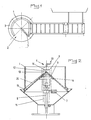
- the device for sorting parts in particular parts of different shapes and dimensions, essentially consists of a cylindrical receptacle 1 for receiving the elements to be separated having an opening 2 in its vertical wall, by a conical element 3 placed under the cylindrical receptacle 1, forming the movable bottom of the latter, and driven in rotation and by a means 4 for adjusting the spacing between the conical element 3 and the lower part of the wall of the cylindrical receptacle 1.
- the cylindrical receptacle 1 is advantageously in the form of a vertical wall extending along a portion of a circle and the opening 2 of which is delimited at one end by a second vertical wall 5 perpendicular to the tangent passing through the first and intended to retain the parts spilled from the mold.
- this second vertical wall 5 is disposed on the side for introducing the pieces to be sorted, which is opposite to that for rejecting the pieces of large size which are ejected by the conical element 3 during its rotation.
- the conical element 3, placed under the cylindrical receptacle 1, is rotated by means of a friction clutch 6 and of a geared motor assembly 7 or of a direct current motor fitted with a variator mounted, preferably, on the support axis 8 of the conical element 3.
- the latter advantageously has grooves, ridges or slight undulations 24 sui vant its generatrices, these grooves, ridges or undulations extending inside the perimeter delimited by the receptacle 1 ( Figures 1 and 2).
- the large-sized parts taken between the large surface of the conical element 3 and the lower part of the cylindrical receptacle 1, are, first of all, wedged between the two surfaces and, therefore, then put into rotation , so that there is a mixing of the parts contained in the receptacle 1 causing their separation and a natural elimination by gravity of the small parts.
- the means 4 for adjusting the spacing between the conical element 3 and the lower part of the wall of the cylindrical receptacle 1 is constituted by a support bearing 9 secured to the external face of the wall of the cylindrical receptacle 1 and provided with a blind housing 10 cooperating with a vertical guide means 11 in the form of an axis and by a threaded rod 12 penetrating into said vertical guide means 11, this rod 12 being provided with a device 13 for actuation in rotation in the form a knurled button or a crank pressing on the external face of the housing 10 and being held in said housing 10 by means of a shoulder 14 or an attached ring.
- the mounting of the threaded rod 12 in the closure wall of the housing 10 is of a type known in the art and does not require any additional description. With this means 4, it is possible to make a fine adjustment of the spacing between the lower part of the wall of the cylindrical receptacle 1 and the surface of the conical element 3, allowing perfect sorting of the parts to be separated.
- the lower part of the wall of the cylindrical receptacle 1 is advantageously provided with a flap 15 of frustoconical shape, extending towards the outside of the receptacle 1, parallel to the conical element 3.
- This flap 15 is intended to retain large parts template during the rotation of element 3 and to avoid their accidental passage simultaneously with that of small parts.
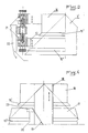
- Figures 3 and 4 of the accompanying drawings show an alternative embodiment of the invention in which the device comprises two cylindrical receptacles 16 and 17 for receiving the elements or parts to be separated having different diameters and mounted concentrically, on the one hand, to the conical element 3 ′ and, on the other hand, between them, these receptacles 16 and 17 being provided with a common retaining plate 18 extending radially and closing the discharge zone and the cylindrical receptacle 17 of larger diameter being provided with a movable inclined wall 19 for retaining and discharging sorted parts cooperating with a clearance 20 provided for this purpose in the wall of the receptacle 17.
- the receptacles 16 and 17 are adjustable vertically with respect to the conical element 3 ′ by means of guide and adjustment devices with screws 21 cooperating with a support 22.
- the adjustment devices 21 are comparable to means 4 of the device according to the figures 1 and 2 and are not described in more detail. These devices therefore also allow a variation in the spacing of the lower part of the wall of the receptacles 16 and 17, in particular of their flap 15 ′ and 15 ⁇ , depending on the parts or elements to be separated.
- the movable inclined wall 19 for retaining and discharging sorted parts is advantageously fixed to a slide 23 mounted adjustable in position on the wall of the receptacle 17 by means of screws.
- the driving of the conical element 3 ′ can be carried out in the same way as for the aforementioned conical element 3.
- the device according to Figures 3 and 4 allows the separation of parts having three different sizes. Indeed, the parts poured into the receptacle 16 can undergo a first separation during the which the larger pieces are discharged through the opening of the wall of said receptacle, fall on the movable inclined wall 19 which directs them to a receiving tank.
- the parts of medium and small sizes can cross the space delimited between the flap 15 ′ of the wall of the receptacle 16 and the conical element 3 ′ to arrive in the receptacle 17, in which the parts of smaller size cross the space between the flap 15 ⁇ of the wall of the receptacle 17 and the conical element 3 ′, to be recovered in a receiving tank, while the pieces of medium size, which cannot pass through this space, are scraped by the movable inclined wall 19 and pass through the clearance 20 provided for this purpose in the wall of the receptacle 17.
- the vertical wall 5, the common retaining plate 18 and the movable inclined wall 19 are advantageously provided, on their side facing the conical element 3 or 3 ′, with a flexible strip 24 cooperating with the surface of said conical element 3 or 3 ′, thus allowing the passage of grooves, ridges or slight undulations 24, provided on the surface of the latter.
- the device according to the invention can be placed directly under a mold or at the end of a carpet or sorting table, the parts or elements to be sorted being poured into an area close to the vertical retaining wall.
- the shape of the cone causes permanent instability of the parts or elements which are poured into the device, which results in rapid evacuation of the elements or parts of small size, while those of large size are evacuated during the rotation of the conical element 3.
- the device according to the invention can be used, due to its autonomy and its small size, both in a fixed position near an injection press, and directly in such a press where it will act as a receiver pieces and carrots.
Landscapes
- Combined Means For Separation Of Solids (AREA)
- Sorting Of Articles (AREA)
Abstract
Description
- La présente invention concerne le domaine du tri de pièces de formes et de dimensions différentes, notamment de pièces d'injection plastique, et a pour objet un dispositif de tri adapté à cet effet.
- Dans le domaine particulier de l'injection plastique, la carotte est à l'image du canal d'injection des différents types de moules et permet l'alimentation des empreintes. Cette carotte est donc de forme et de dimension très variable de sorte que sa séparation, par tri, des pièces de moulage est très difficile à réaliser.
- A cet effet, il existe actuellement divers dispositifs de séparation des carottes et des pièces moulées, qui se présentent généralement sous forme d'éléments présentant entre eux des plans parallèles, rectilignes, dont l'écartement est réglable. Ces dispositifs ne permettent, cependant pas, en fonctionnement, des cotes identiques sur les éléments à séparer.
- Dans ces dispositifs connus, les éléments de grand gabarit sont séparés au moyen de rouleaux à spires ou à palettes ou de tables vibrantes des éléments de faible gabarit, qui sont évacués par gravité, par prise en compte de l'inclinaison de la table de réception des trieurs, ou par chute libre après passage entre les moyens de séparation des éléments de grand gabarit. Ces derniers peuvent ainsi être amenés à un réceptacle de réception, à une table, ou à un tapis transporteur.
- Ces dispositifs connus présentent, cependant, un certain nombre d'inconvénients, à savoir, d'une part, d'avoir un champ d'application très limité, plusieurs séparateurs de conception différente étant nécessaires dès lors que les éléments à séparer ou à trier présen tent une grande variété de formes et de dimensions, d'autre part, de nécessiter une mise au point longue et coûteuse et, enfin, de présenter un risque d'accumulation des carottes rendant la séparation des pièces impossible, du fait de leur efficacité limitée. En outre, dans ces dispositifs connus, il subsiste un risque important d'accrochage des carottes et des pièces entraînant un enchevêtrement de celles-ci et donc le blocage desdits dispositifs et leur degré d'autonomie ainsi que leur encombrement ne permettent pas leur montage directe dans la presse à injection ou à proximité immédiate de celle-ci.
- La présente invention a pour but de pallier ces inconvénients.
- Elle a, en effet, pour objet un dispositif de tri de pièces, en particulier de pièces de formes et de dimensions différentes, caractérisé en ce qu'il est essentiellement constitué par un réceptacle cylindrique de réception des éléments à séparer présentant une ouverture dans sa paroi verticale, par un élément conique disposé sous le réceptacle cylindrique, formant le fond mobile de ce dernier, et entraîné en rotation et par un moyen de réglage de l'écartement entre l'élément conique et la partie inférieure de la paroi du réceptacle cylindrique.
- L'invention sera mieux comprise, grâce à la description ci-après, qui se rapporte à des modes de réalisation préférés, donnés à titre d'exemples non limitatifs, et expliqués avec référence aux dessins schématiques annexés, dans lesquels :
- la figure 1 est une vue en plan du dispositif conforme à l'invention ;
- la figure 2 est une vue en élévation latérale et en coupe du dispositif suivant la figure 1 ;
- la figure 3 est une vue partielle en coupe d'une variante de réalisation de l'invention, et
- la figure 4 est une vue partielle en élévation du dispositif suivant la figure 3.
- Conformément à l'invention, et comme le montrent plus particulièrement, à titre d'exemple, les figures 1 et 2 des dessins annexés, le dispositif de tri de pièces, en particulier de pièces de formes et de dimensions différentes est essentiellement constitué par un réceptacle cylindrique 1 de réception des éléments à séparer présentant une ouverture 2 dans sa paroi verticale, par un élément conique 3 disposé sous le réceptacle cylindrique 1, formant le fond mobile de ce dernier, et entraîné en rotation et par un moyen 4 de réglage de l'écartement entre l'élément conique 3 et la partie inférieure de la paroi du réceptacle cylindrique 1.
- Le réceptacle cylindrique 1 est avantageusement sous forme d'une paroi verticale s'étendant suivant une portion de cercle et dont l'ouverture 2 est délimitée à une extrémité par une deuxième paroi verticale 5 perpendiculaire à la tangente passant par la première et destinée à retenir les pièces déversées par le moule. En effet, cette deuxième paroi verticale 5 est disposée du côté d'introduction des pièces à trier, qui est opposée à celui de rejet des pièces de grand gabarit qui sont éjectées par l'élément conique 3 lors de sa rotation.
- L'élément conique 3, disposé sous le réceptacle cylindrique 1, est entraîné en rotation par l'intermédiaire d'un embrayage à friction 6 et d'un ensemble motoréducteur 7 ou d'un moteur à courant continu équipé d'un variateur montés, de préférence, sur l'axe de support 8 de l'élément conique 3. Afin de réaliser un bon entraînment des pièces, et en particulier une mobilité des pièces de grand gabarit destinée à éviter une imbrication de ces dernières avec les pièces de petite dimension devant être évacuées entre la partie inférieure du réceptacle cylindrique 1 et la surface de l'élément conique 3, cette dernière présente avantageusement des rainures, des stries ou de légers vallonnements 24 sui vant ses génératrices, ces rainures, stries ou vallonnements s'étendant à l'intérieur du périmètre délimité par le réceptacle 1 (figures 1 et 2). Ainsi, les pièces de grand gabarit, prises entre la grande surface de l'élément conique 3 et la partie inférieure du réceptacle cylindrique 1, sont, dans un premier temps, coincées entre les deux surfaces et, de ce fait, mises ensuite en rotation, de sorte qu'il se produit un brassage des pièces contenues dans le réceptacle 1 entraînant leur séparation et une élimination naturelle par gravité des pièces de petite dimension.
- Le moyen 4 de réglage de l'écartement entre l'élément conique 3 et la partie inférieure de la paroi du réceptacle cylindrique 1 est constitué par un palier de support 9 solidaire de la face externe de la paroi du réceptacle cylindrique 1 et muni d'un logement borgne 10 coopérant avec un moyen de guidage vertical 11 sous forme d'un axe et par une tige filetée 12 pénétrant dans ledit moyen de guidage vertical 11, cette tige 12 étant pourvue d'un dispositif 13 d'actionnement en rotation sous forme d'un bouton moleté ou d'une manivelle s'appuyant sur la face externe du logement 10 et étant maintenue dans ledit logement 10 au moyen d'un épaulement 14 ou d'une bague rapportée. Le montage de la tige filetée 12 dans la paroi de fermeture du logement 10 est d'un type connu dans la technique et ne nécessite pas de description complémentaire. Grâce à ce moyen 4, il est possible de réaliser un réglage fin de l'écartement entre la partie inférieure de la paroi du réceptacle cylindrique 1 et la surface de l'élément conique 3, permettant un tri parfait des pièces à séparer.
- Selon une autre caractéristique de l'invention, la partie inférieure de la paroi du réceptacle cylindrique 1 est avantageusement pourvue d'une bavette 15 de forme tronconique, s'étendant vers l'extérieur du réceptacle 1, parallèlement à l'élément conique 3. Cette bavette 15 est destinée à retenir les pièces de grand gabarit pendant la rotation de l'élément 3 et à éviter leur passage accidentel simultanément avec celui des pièces de petite dimension.
- Les figures 3 et 4 des dessins annexés représentent une variante de réalisation de l'invention dans laquelle le dispositif comporte deux réceptacles cylindriques 16 et 17 de réception des éléments ou pièces à séparer présentant des diamètres différents et montés concentriquement, d'une part, à l'élément conique 3′ et, d'autre part, entre eux, ces réceptacles 16 et 17 étant munis d'une tôle de retenue commune 18 s'étendant radialement et fermant la zone de déversement et le réceptacle cylindrique 17 de plus grand diamètre étant pourvu d'une paroi inclinée mobile 19 de retenue et d'évacuation de pièces triées coopérant avec un dégagement 20 prévu à cet effet dans la paroi du réceptacle 17.
- Les réceptacles 16 et 17 sont réglables verticalement par rapport à l'élément conique 3′ au moyen de dispositifs de guidage et de réglage à vis 21 coopérant avec un support 22. Les dispositifs 21 de réglage sont comparables au moyen 4 du dispositif selon les figures 1 et 2 et ne sont pas décrits plus en détail. Ces dispositifs permettent donc également une variation de l'écartement de la partie inférieure de la paroi des réceptacles 16 et 17, en particulier de leur bavette 15′ et 15˝, en fonction des pièces ou éléments à séparer.
- La paroi inclinée mobile 19 de retenue et d'évacuation de pièces triées est avantageusement fixée sur un coulisseau 23 montée réglable en position sur la paroi du réceptacle 17 au moyen de vis.
- L'entraînment de l'élément conique 3′ peut être effectué de la même manière que pour l'élément conique 3 précité.
- Le dispositif selon les figures 3 et 4 permet la séparation de pièces présentant trois gabarits différents. En effet, les pièces déversées dans le réceptacle 16 peuvent subir une première séparation lors de la quelle les pièces de plus grande dimension sont évacuées à travers l'ouverture de la paroi dudit réceptacle, tombent sur la paroi inclinée mobile 19 qui les dirige vers un bac de réception. Les pièces de gabarits moyen et faible peuvent traverser l'espace délimité entre la bavette 15′ de la paroi du réceptacle 16 et l'élément conique 3′ pour arriver dans le réceptacle 17, dans lequel les pièces de plus petit gabarit traversent l'espace entre la bavette 15˝ de la paroi du réceptacle 17 et l'élément conique 3′, pour être récupérées dans un bac de réception, tandis que les pièces de gabarit moyen, qui ne peuvent traverser cet espace, sont raclées par la paroi inclinée mobile 19 et traversent le dégagement 20 prévu à cet effet dans la paroi du réceptacle 17.
- Conformément à une autre caractéristique de l'invention, la paroi verticale 5, la tôle de retenue commune 18 et la paroi inclinée mobile 19 sont avantageusement pourvues, sur leur côté tourné vers l'élément conique 3 ou 3′, d'une bande souple 24 coopérant avec la surface dudit élément conique 3 ou 3′, permettant ainsi le passage des rainures, stries ou légers vallonnements 24, prévus à la surface de ce dernier.
- Le dispositif conforme à l'invention peut être placé directement sous un moule ou à l'extrémité d'un tapis ou d'une table de tri, les pièces ou éléments à trier étant déversés dans une zone proche de la paroi verticale de retenue. La forme du cône entraîne une instabilité permanente des pièces ou éléments qui sont déversés dans le dispositif, ce qui a pour conséquence une évacuation rapide des éléments ou pièces de faible gabarit, tandis que ceux de grand gabarit sont évacués lors de la rotation de l'élément conique 3.
- Enfin, le dispositif conforme à l'invention peut être utilisé, du fait de son autonomie et de son faible encombrement, aussi bien en poste fixe à proximité d'une presse à injection, que directement dans une telle presse où il fera office de récepteur des pièces et des carottes.
- Bien entendu, l'invention n'est pas limitée aux modes de réalisation décrits et représentés aux dessins annexés. Des modifications restent possibles, notamment du point de vue de la constitution des divers éléments ou par substitution d'équivalents techniques, sans sortir pour autant du domaine de protection de l'invention.
Claims (10)
Priority Applications (1)
| Application Number | Priority Date | Filing Date | Title |
|---|---|---|---|
| AT89440123T ATE86150T1 (de) | 1988-11-18 | 1989-11-16 | Vorrichtung zum sortieren von stuecken, insbesondere von stuecken mit verschiedenen formen und groessen. |
Applications Claiming Priority (2)
| Application Number | Priority Date | Filing Date | Title |
|---|---|---|---|
| FR8815222 | 1988-11-18 | ||
| FR8815222A FR2639262B1 (fr) | 1988-11-18 | 1988-11-18 | Dispositif de tri de pieces, en particulier de pieces de formes et de dimensions differentes |
Publications (2)
| Publication Number | Publication Date |
|---|---|
| EP0369912A1 true EP0369912A1 (fr) | 1990-05-23 |
| EP0369912B1 EP0369912B1 (fr) | 1993-03-03 |
Family
ID=9372128
Family Applications (1)
| Application Number | Title | Priority Date | Filing Date |
|---|---|---|---|
| EP89440123A Expired - Lifetime EP0369912B1 (fr) | 1988-11-18 | 1989-11-16 | Dispositif de tri de pièces, en particulier de pièces de formes et de dimensions différentes |
Country Status (5)
| Country | Link |
|---|---|
| EP (1) | EP0369912B1 (fr) |
| AT (1) | ATE86150T1 (fr) |
| DE (1) | DE68905148T2 (fr) |
| ES (1) | ES2040493T3 (fr) |
| FR (1) | FR2639262B1 (fr) |
Cited By (1)
| Publication number | Priority date | Publication date | Assignee | Title |
|---|---|---|---|---|
| CN116553059A (zh) * | 2023-07-07 | 2023-08-08 | 成都飞机工业(集团)有限责任公司 | 一种人机结合的高效物料拣选设备及方法 |
Citations (3)
| Publication number | Priority date | Publication date | Assignee | Title |
|---|---|---|---|---|
| US4257883A (en) * | 1979-02-12 | 1981-03-24 | Realex Corporation | Parts sorting mechanism |
| FR2485957A1 (fr) * | 1980-07-01 | 1982-01-08 | Fratellia Aldo | Appareil pour trier des produits fragiles comportant des chemins de roulement inclines et superposes |
| US4342396A (en) * | 1980-08-11 | 1982-08-03 | Nelmor Company, Inc. | Rotary parts separator |
-
1988
- 1988-11-18 FR FR8815222A patent/FR2639262B1/fr not_active Expired - Lifetime
-
1989
- 1989-11-16 EP EP89440123A patent/EP0369912B1/fr not_active Expired - Lifetime
- 1989-11-16 AT AT89440123T patent/ATE86150T1/de not_active IP Right Cessation
- 1989-11-16 DE DE89440123T patent/DE68905148T2/de not_active Expired - Fee Related
- 1989-11-16 ES ES198989440123T patent/ES2040493T3/es not_active Expired - Lifetime
Patent Citations (3)
| Publication number | Priority date | Publication date | Assignee | Title |
|---|---|---|---|---|
| US4257883A (en) * | 1979-02-12 | 1981-03-24 | Realex Corporation | Parts sorting mechanism |
| FR2485957A1 (fr) * | 1980-07-01 | 1982-01-08 | Fratellia Aldo | Appareil pour trier des produits fragiles comportant des chemins de roulement inclines et superposes |
| US4342396A (en) * | 1980-08-11 | 1982-08-03 | Nelmor Company, Inc. | Rotary parts separator |
Cited By (2)
| Publication number | Priority date | Publication date | Assignee | Title |
|---|---|---|---|---|
| CN116553059A (zh) * | 2023-07-07 | 2023-08-08 | 成都飞机工业(集团)有限责任公司 | 一种人机结合的高效物料拣选设备及方法 |
| CN116553059B (zh) * | 2023-07-07 | 2023-11-10 | 成都飞机工业(集团)有限责任公司 | 一种人机结合的高效物料拣选设备及方法 |
Also Published As
| Publication number | Publication date |
|---|---|
| DE68905148T2 (de) | 1993-11-18 |
| DE68905148D1 (de) | 1993-04-08 |
| FR2639262B1 (fr) | 1991-03-15 |
| FR2639262A1 (fr) | 1990-05-25 |
| EP0369912B1 (fr) | 1993-03-03 |
| ES2040493T3 (es) | 1993-10-16 |
| ATE86150T1 (de) | 1993-03-15 |
Similar Documents
| Publication | Publication Date | Title |
|---|---|---|
| FR2834436A3 (fr) | Extracteur de jus de fruits et de legumes | |
| FR3004893A1 (fr) | Dispositif de piegeage a moyens de jonction | |
| EP1826155A1 (fr) | Dispositif de distribution contrôlée d'objets introduits en vrac dans un bol vibrant, système correspondant | |
| FR2491040A1 (fr) | Appareil de distribution de composants de circuits electriques | |
| FR2600049A1 (fr) | Dispositif de retenue d'un objet a l'entree d'un canal d'empilement. | |
| EP1077891B1 (fr) | Mecanisme d'orientation et de distrubution automatique de pieces | |
| EP0369912B1 (fr) | Dispositif de tri de pièces, en particulier de pièces de formes et de dimensions différentes | |
| FR2538797A1 (fr) | Dispositif d'empilage d'objets plats | |
| EP0233233A1 (fr) | Procede et dispositif pour ouvrir par la zone mediane de leur corps, vider et aplatir des recipients metalliques ou composites hermetiquement fermes | |
| FR2791284A1 (fr) | Dispositif de compactage d'emballages, tels que bouteilles ou canettes | |
| FR2538718A1 (fr) | Roue de broyeur centrifuge | |
| FR2765814A1 (fr) | Dispositif de tri des recipients et emballages | |
| EP0088028B1 (fr) | Tamis de maçon | |
| FR2477369A1 (fr) | Mangeoire pour animaux domestiques | |
| EP1147834B1 (fr) | Emporte-pièces | |
| EP2949438B1 (fr) | Broyeur de végétaux pour réaliser des particules calibrées | |
| FR3097535A1 (fr) | Dispositif d’ouverture par découpe de colis, notamment de colis en carton | |
| EP4656555A1 (fr) | Recuperateur magnetique de couverts pour vide-ordures, ensemble pour vide-ordures et vide-ordures le comprenant | |
| FR2673928A3 (fr) | Outil pour enlever le capuchon en metal de biberons de laboratoire. | |
| FR2836016A1 (fr) | Dispositif d'extractions de jus d'agrumes | |
| FR2687216A1 (fr) | Dispositif et procede de demoulage d'objets renfermes dans un moule ouvert en matiere deformable, notamment un bac a glacons. | |
| FR3165792A1 (fr) | Système d’étalement d’un cordon de pâte le long d’une paroi interne d’une chambre cylindrique | |
| FR2706795A1 (en) | Device for separating moulded components injected as a cluster | |
| FR2629421A1 (fr) | Tiroir pour appareil de conditionnement de produits pateux | |
| EP1474988B1 (fr) | Dispositif destiné à la séparation de la mie et de la croûte d'un pain |
Legal Events
| Date | Code | Title | Description |
|---|---|---|---|
| PUAI | Public reference made under article 153(3) epc to a published international application that has entered the european phase |
Free format text: ORIGINAL CODE: 0009012 |
|
| AK | Designated contracting states |
Kind code of ref document: A1 Designated state(s): AT BE CH DE ES GB IT LI LU NL SE |
|
| 17P | Request for examination filed |
Effective date: 19900924 |
|
| 17Q | First examination report despatched |
Effective date: 19910904 |
|
| GRAA | (expected) grant |
Free format text: ORIGINAL CODE: 0009210 |
|
| AK | Designated contracting states |
Kind code of ref document: B1 Designated state(s): AT BE CH DE ES GB IT LI LU NL SE |
|
| PG25 | Lapsed in a contracting state [announced via postgrant information from national office to epo] |
Ref country code: SE Effective date: 19930303 Ref country code: NL Effective date: 19930303 Ref country code: GB Effective date: 19930303 |
|
| REF | Corresponds to: |
Ref document number: 86150 Country of ref document: AT Date of ref document: 19930315 Kind code of ref document: T |
|
| REF | Corresponds to: |
Ref document number: 68905148 Country of ref document: DE Date of ref document: 19930408 |
|
| ITF | It: translation for a ep patent filed | ||
| NLV1 | Nl: lapsed or annulled due to failure to fulfill the requirements of art. 29p and 29m of the patents act | ||
| GBV | Gb: ep patent (uk) treated as always having been void in accordance with gb section 77(7)/1977 [no translation filed] |
Effective date: 19930303 |
|
| REG | Reference to a national code |
Ref country code: ES Ref legal event code: FG2A Ref document number: 2040493 Country of ref document: ES Kind code of ref document: T3 |
|
| PG25 | Lapsed in a contracting state [announced via postgrant information from national office to epo] |
Ref country code: LU Free format text: LAPSE BECAUSE OF NON-PAYMENT OF DUE FEES Effective date: 19931130 |
|
| PLBE | No opposition filed within time limit |
Free format text: ORIGINAL CODE: 0009261 |
|
| STAA | Information on the status of an ep patent application or granted ep patent |
Free format text: STATUS: NO OPPOSITION FILED WITHIN TIME LIMIT |
|
| 26N | No opposition filed | ||
| PGFP | Annual fee paid to national office [announced via postgrant information from national office to epo] |
Ref country code: BE Payment date: 19961129 Year of fee payment: 8 Ref country code: AT Payment date: 19961129 Year of fee payment: 8 |
|
| PG25 | Lapsed in a contracting state [announced via postgrant information from national office to epo] |
Ref country code: AT Free format text: LAPSE BECAUSE OF NON-PAYMENT OF DUE FEES Effective date: 19971116 |
|
| PGFP | Annual fee paid to national office [announced via postgrant information from national office to epo] |
Ref country code: ES Payment date: 19971128 Year of fee payment: 9 |
|
| PG25 | Lapsed in a contracting state [announced via postgrant information from national office to epo] |
Ref country code: BE Free format text: LAPSE BECAUSE OF NON-PAYMENT OF DUE FEES Effective date: 19971130 |
|
| PGFP | Annual fee paid to national office [announced via postgrant information from national office to epo] |
Ref country code: CH Payment date: 19980227 Year of fee payment: 9 |
|
| BERE | Be: lapsed |
Owner name: HEINIMANN GERARD Effective date: 19971130 |
|
| PG25 | Lapsed in a contracting state [announced via postgrant information from national office to epo] |
Ref country code: ES Free format text: LAPSE BECAUSE OF NON-PAYMENT OF DUE FEES Effective date: 19981117 |
|
| PG25 | Lapsed in a contracting state [announced via postgrant information from national office to epo] |
Ref country code: LI Free format text: LAPSE BECAUSE OF NON-PAYMENT OF DUE FEES Effective date: 19981130 Ref country code: CH Free format text: LAPSE BECAUSE OF NON-PAYMENT OF DUE FEES Effective date: 19981130 |
|
| REG | Reference to a national code |
Ref country code: CH Ref legal event code: PL |
|
| PGFP | Annual fee paid to national office [announced via postgrant information from national office to epo] |
Ref country code: DE Payment date: 20011205 Year of fee payment: 13 |
|
| PG25 | Lapsed in a contracting state [announced via postgrant information from national office to epo] |
Ref country code: DE Free format text: LAPSE BECAUSE OF NON-PAYMENT OF DUE FEES Effective date: 20030603 |
|
| REG | Reference to a national code |
Ref country code: ES Ref legal event code: FD2A Effective date: 19991214 |
|
| PG25 | Lapsed in a contracting state [announced via postgrant information from national office to epo] |
Ref country code: IT Free format text: LAPSE BECAUSE OF NON-PAYMENT OF DUE FEES Effective date: 20051116 |