EP0369914B1 - Verfahren zum Verbinden eines Matrixmaterials mit einem Funktionsträger und mit diesem Verfahren hergestellte Vorrichtungen - Google Patents
Verfahren zum Verbinden eines Matrixmaterials mit einem Funktionsträger und mit diesem Verfahren hergestellte Vorrichtungen Download PDFInfo
- Publication number
- EP0369914B1 EP0369914B1 EP89440125A EP89440125A EP0369914B1 EP 0369914 B1 EP0369914 B1 EP 0369914B1 EP 89440125 A EP89440125 A EP 89440125A EP 89440125 A EP89440125 A EP 89440125A EP 0369914 B1 EP0369914 B1 EP 0369914B1
- Authority
- EP
- European Patent Office
- Prior art keywords
- profile
- connection part
- concrete
- support
- profiles
- Prior art date
- Legal status (The legal status is an assumption and is not a legal conclusion. Google has not performed a legal analysis and makes no representation as to the accuracy of the status listed.)
- Expired - Lifetime
Links
- 238000000034 method Methods 0.000 title claims abstract description 12
- 239000011159 matrix material Substances 0.000 title 1
- 239000004567 concrete Substances 0.000 claims abstract description 52
- 230000002787 reinforcement Effects 0.000 claims description 31
- 239000000463 material Substances 0.000 claims description 13
- 238000005520 cutting process Methods 0.000 claims description 9
- 239000002184 metal Substances 0.000 claims description 5
- 229910052751 metal Inorganic materials 0.000 claims description 5
- 230000002829 reductive effect Effects 0.000 claims description 4
- 238000005096 rolling process Methods 0.000 claims description 3
- 238000012546 transfer Methods 0.000 claims description 3
- 239000011324 bead Substances 0.000 claims description 2
- 238000005242 forging Methods 0.000 claims description 2
- 229920002994 synthetic fiber Polymers 0.000 claims description 2
- 238000009415 formwork Methods 0.000 abstract description 16
- 230000003014 reinforcing effect Effects 0.000 description 20
- XEEYBQQBJWHFJM-UHFFFAOYSA-N Iron Chemical compound [Fe] XEEYBQQBJWHFJM-UHFFFAOYSA-N 0.000 description 10
- 238000005452 bending Methods 0.000 description 8
- 229910000831 Steel Inorganic materials 0.000 description 7
- 238000010276 construction Methods 0.000 description 7
- 238000012423 maintenance Methods 0.000 description 7
- 239000010959 steel Substances 0.000 description 7
- 238000009434 installation Methods 0.000 description 6
- 229910052742 iron Inorganic materials 0.000 description 5
- 238000004519 manufacturing process Methods 0.000 description 5
- 238000003466 welding Methods 0.000 description 5
- 230000036961 partial effect Effects 0.000 description 4
- 238000005266 casting Methods 0.000 description 3
- 238000006073 displacement reaction Methods 0.000 description 2
- 230000000694 effects Effects 0.000 description 2
- 230000009467 reduction Effects 0.000 description 2
- 239000011150 reinforced concrete Substances 0.000 description 2
- 238000010008 shearing Methods 0.000 description 2
- 238000010521 absorption reaction Methods 0.000 description 1
- 230000004888 barrier function Effects 0.000 description 1
- 239000000919 ceramic Substances 0.000 description 1
- 230000003749 cleanliness Effects 0.000 description 1
- 230000006835 compression Effects 0.000 description 1
- 238000007906 compression Methods 0.000 description 1
- 238000009826 distribution Methods 0.000 description 1
- 230000003100 immobilizing effect Effects 0.000 description 1
- 230000000977 initiatory effect Effects 0.000 description 1
- 238000003780 insertion Methods 0.000 description 1
- 230000037431 insertion Effects 0.000 description 1
- 238000009413 insulation Methods 0.000 description 1
- 230000001788 irregular Effects 0.000 description 1
- 230000000670 limiting effect Effects 0.000 description 1
- 230000014759 maintenance of location Effects 0.000 description 1
- 238000012986 modification Methods 0.000 description 1
- 230000004048 modification Effects 0.000 description 1
- 238000000465 moulding Methods 0.000 description 1
- 238000009417 prefabrication Methods 0.000 description 1
- 230000036316 preload Effects 0.000 description 1
- 238000002360 preparation method Methods 0.000 description 1
- 230000008569 process Effects 0.000 description 1
- 230000000750 progressive effect Effects 0.000 description 1
- 238000011084 recovery Methods 0.000 description 1
- 230000008439 repair process Effects 0.000 description 1
- 230000002441 reversible effect Effects 0.000 description 1
- 238000007789 sealing Methods 0.000 description 1
- 125000006850 spacer group Chemical group 0.000 description 1
- 238000006467 substitution reaction Methods 0.000 description 1
- XLYOFNOQVPJJNP-UHFFFAOYSA-N water Substances O XLYOFNOQVPJJNP-UHFFFAOYSA-N 0.000 description 1
Images

Classifications
-
- B—PERFORMING OPERATIONS; TRANSPORTING
- B28—WORKING CEMENT, CLAY, OR STONE
- B28B—SHAPING CLAY OR OTHER CERAMIC COMPOSITIONS; SHAPING SLAG; SHAPING MIXTURES CONTAINING CEMENTITIOUS MATERIAL, e.g. PLASTER
- B28B23/00—Arrangements specially adapted for the production of shaped articles with elements wholly or partly embedded in the moulding material; Production of reinforced objects
-
- E—FIXED CONSTRUCTIONS
- E04—BUILDING
- E04B—GENERAL BUILDING CONSTRUCTIONS; WALLS, e.g. PARTITIONS; ROOFS; FLOORS; CEILINGS; INSULATION OR OTHER PROTECTION OF BUILDINGS
- E04B5/00—Floors; Floor construction with regard to insulation; Connections specially adapted therefor
- E04B5/16—Load-carrying floor structures wholly or partly cast or similarly formed in situ
- E04B5/17—Floor structures partly formed in situ
- E04B5/23—Floor structures partly formed in situ with stiffening ribs or other beam-like formations wholly or partly prefabricated
- E04B5/29—Floor structures partly formed in situ with stiffening ribs or other beam-like formations wholly or partly prefabricated the prefabricated parts of the beams consisting wholly of metal
-
- E—FIXED CONSTRUCTIONS
- E04—BUILDING
- E04C—STRUCTURAL ELEMENTS; BUILDING MATERIALS
- E04C3/00—Structural elongated elements designed for load-supporting
- E04C3/02—Joists; Girders, trusses, or trusslike structures, e.g. prefabricated; Lintels; Transoms; Braces
- E04C3/29—Joists; Girders, trusses, or trusslike structures, e.g. prefabricated; Lintels; Transoms; Braces built-up from parts of different material, i.e. composite structures
- E04C3/293—Joists; Girders, trusses, or trusslike structures, e.g. prefabricated; Lintels; Transoms; Braces built-up from parts of different material, i.e. composite structures the materials being steel and concrete
-
- E—FIXED CONSTRUCTIONS
- E04—BUILDING
- E04C—STRUCTURAL ELEMENTS; BUILDING MATERIALS
- E04C3/00—Structural elongated elements designed for load-supporting
- E04C3/02—Joists; Girders, trusses, or trusslike structures, e.g. prefabricated; Lintels; Transoms; Braces
- E04C3/29—Joists; Girders, trusses, or trusslike structures, e.g. prefabricated; Lintels; Transoms; Braces built-up from parts of different material, i.e. composite structures
- E04C3/293—Joists; Girders, trusses, or trusslike structures, e.g. prefabricated; Lintels; Transoms; Braces built-up from parts of different material, i.e. composite structures the materials being steel and concrete
- E04C3/294—Joists; Girders, trusses, or trusslike structures, e.g. prefabricated; Lintels; Transoms; Braces built-up from parts of different material, i.e. composite structures the materials being steel and concrete of concrete combined with a girder-like structure extending laterally outside the element
-
- E—FIXED CONSTRUCTIONS
- E04—BUILDING
- E04B—GENERAL BUILDING CONSTRUCTIONS; WALLS, e.g. PARTITIONS; ROOFS; FLOORS; CEILINGS; INSULATION OR OTHER PROTECTION OF BUILDINGS
- E04B5/00—Floors; Floor construction with regard to insulation; Connections specially adapted therefor
- E04B5/16—Load-carrying floor structures wholly or partly cast or similarly formed in situ
- E04B5/17—Floor structures partly formed in situ
- E04B5/23—Floor structures partly formed in situ with stiffening ribs or other beam-like formations wholly or partly prefabricated
- E04B2005/232—Floor structures partly formed in situ with stiffening ribs or other beam-like formations wholly or partly prefabricated with special provisions for connecting wooden stiffening ribs or other wooden beam-like formations to the concrete slab
- E04B2005/235—Wooden stiffening ribs or other wooden beam-like formations having a special form
Definitions
- the present invention relates to the field of public works and civil engineering, in particular the production of concrete slabs with steel frames, for example for bridges and buildings, and relates to a method of securing a mass of material to a functional support.
- the invention also relates to devices obtained by implementing this method.
- Steel-framed concrete slabs called mixed frameworks are generally made up of steel beams and reinforcement and concrete, the whole being cased and poured on site.
- the drawback of such a process lies in the fact that it requires a relatively long production time, the construction not being industrialized and being subjected to climatic vagaries and to the concrete hardening period which is 28 days.
- the material used for the support profiles is generally not used to the maximum of its possibilities, after installation, the upper part of these profiles, linked to the concrete, being little stressed mechanically, while the lower part of the profile is tense.
- the upper part of the profile is only necessary during the short period when the profile must carry the soft concrete, and constitutes a stiffening intended to prevent its spillage or buckling and serves to retain the lost formwork.
- connection between the support profile and the reinforcement of the concrete slab is often ensured by an attached connector, fixed by welding to the support profile.
- an attached connector fixed by welding to the support profile.
- Such an embodiment is relatively expensive, because it requires careful welding of said connectors.
- FR-A-2 578 276 describes a concrete construction element, in particular a floor, consisting of support beams of reinforced concrete secured to the floor itself during the casting of the latter and by cooperation with the frames of the latter.
- This document also relates to a method of producing such a building element using a reverse casting technique followed by a reversal.
- the beams used in this element show projecting hooks, which are only intended for the installation and maintenance of the reinforcement of the floor and not for the housing of connection parts intended for the recovery of essentially vertical forces. , this notion being essential in order to avoid shearing forces at the level of the connection between metallic supports and concrete slabs.
- US-A-2 636 377 discloses a reinforced concrete beam requiring fixing of the transverse steels.
- the metal beam has in its upper part an added element provided with perforations obtained by stamping.
- GB-A-396 569 also discloses a metal profile intended to be partially embedded in a floor element and to cooperate for this purpose with reinforcing elements, the projecting part preferably extending under the floor element. .
- DE-U-8 714 517 describes support profile elements with a T-shaped cross section and provided on their vertical core with cutouts intended to prevent a displacement of longitudinal sliding. These cutouts are only intended for the installation and the maintenance of transverse reinforcements ensuring the maintenance of the profiles against a longitudinal sliding.
- the present invention proposes to substantially lighten the support profiles, while taking up multi-directional forces and avoiding any possibility of initiation of rupture.
- each support profile comprising a connection part, embedded in the concrete, in one piece with the profile and provided with means intended to cooperate with the reinforcing elements, which are mounted transversely with respect to said elements profiles and are embedded in the concrete, together with the connectors of the profiles, the connection part having a constant section and extending in a rectilinear fashion on the support profit and its means intended to cooperate with the reinforcing elements, which are constituted by cutouts, ensuring the triangulation of the profile between the sole of said profile and the concrete slab, as well as a transfer of the tanks vertical ges, the support profile being constituted in the form of a T-profile, the core of which, forming the connection part, is provided, at regular intervals, with cutouts, substantially in dovetail, said profile and its connection
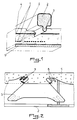
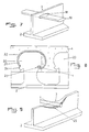
- the device essentially constituted by a concrete slab 4, the reinforcement 1 of which is connected to profiles of support 2 by means of connectors 3 or connection parts and partially embedded in concrete 4, this device being preferably molded in the inverted position, each support profile 2 comprising a connection part 3, embedded in concrete 4, of in one piece with the profile 2 and provided with means intended to cooperate with the reinforcing elements 1, which are mounted transversely relative to the said profiles 2 and are embedded in the concrete 4, together with the connectors 3 of the profiles 2, the part connection 3 having a constant section and extending in a rectilinear manner on the support profile 2 and its means intended to cooperate with the reinforcing elements 1, which are constituted pa r cutouts 5, ensuring the triangulation of the profile 2 between the sole of said profile 2 and the concrete slab 4, as well as a transfer of vertical loads, the support profile 2 being formed in the form of a T-profile, of which the core, forming
- connection between the reinforcement 1 and the sections 2 is made in the submerged part of said sections 2, which are functionally linked to the mass of the concrete 4 via the reinforcements 1.
- Such an embodiment of the device makes it possible to obtain a perfectly flat upper face and an arrangement of the frame 1 in the formwork without the need for spacers, said frame 1 being suspended from the profiles 2 by means of the connectors 3. which are embedded in the concrete 4, so that the positioning of said reinforcement can be carried out much more precisely and without the insertion of foreign bodies.
- Profiles 2, which are generally metal profiles, are intended to be placed on linear or point supports constituting bridges, floors or other walls, and are most often in the form of elements of a few meters or a few tens of meters long associated, individually or in number, with a concrete slab 4 a few meters wide.
- Each support profile 2 comprises a connection part 3 in one piece with the profile 2 and provided, at regular intervals, with cutouts 5 intended to cooperate with the reinforcing elements 1 with a view to housing and / or fixing of these, while ensuring the triangulation of the profile 2 between the sole of said profile 2 and the concrete slab 4.
- cutouts 5 thus achieve the positioning and spacing of the reinforcing elements 1 in two or three dimensions.
- the embodiment of the profiled support 2 and of its connection part 3 in one piece makes it possible to eliminate the subsequent welding operations from part 3 to part 2.
- connection part 3 makes it possible to reduce the various mechanical bending and shearing stresses of the reinforcing elements 1, which oppose the displacement of the mass of material formed by concrete 4, via said connection part 3, on the support profiles 2.
- all of the internal and / or external multidimensional forces exerted on a slab and due, in particular , slipping, lifting and tearing can be resumed.
- connection part 3 embedded in the concrete slab 4 participates, in fact, usefully in the resistance to bending of the support profile 2, which can, therefore, be undersized with respect to its dimensioning. origin.
- connection part 3 has a constant cross-section and extends in a rectilinear manner on the support profile 2 and its cutouts 5 are in the form of opposite hooks cooperating by their bottom with the reinforcing elements 1 freely placed in said hooks.
- the reinforcing elements 1 can easily be put in place in the cut-outs 5 of the connection parts 3 of the profiles 2 after the latter have been disposed in an inverted position above the formwork, by simple engagement in the hooks opposite forming said cutouts 5, said hooks holding the reinforcing elements 1 against a fall in said formwork.
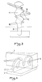
- FIG. 2 represents an alternative embodiment of the support profile 2, constituted in the form of a T-profile, the core of which is provided, at regular intervals, with cutouts 5, substantially dovetail-shaped, whose corner ends, preferably rounded, delimiting said cutouts 5, are each provided with at least one notch 6 for accommodating a flat reinforcing element 7 or one or more adjoining round reinforcing elements.
- This embodiment allows a substantial reduction in the profile 2 due to the cutouts 5 and the installation of flat reinforcing elements 7 taking up precise multi-directional forces or even round reinforcing elements, of which only a part is intended for connection, the others being intended only for the transverse reinforcement of the concrete slab.
- the rounded ends of the corners make it possible to eliminate the incipient fractures.
- a profile element 2 with the connection part 3, according to FIG. 2 can easily be produced by cutting an I or H profile at its core, the symmetry of the cuts 5 making it possible to obtain two profiles 2 to the end of the cut.
- the notches 6, provided at the corner ends of the cutouts 5 of the connection part of the profile according to FIG. 2 cooperate with a flexible frame, the edges of which are inserted in said notches 6.
- the flexible reinforcement is fixed with preload on the connection part 3, so that its retention during the pouring of the concrete into the formwork is ensured.
- several notches 6 can be provided at the ends of the corners of the cutouts 5, it is possible to fix with offset the reinforcing elements 1 or 7 in said notches, so as to achieve transverse prestressing of said reinforcements compared to the profiles 2, which results in their automatic maintenance during the formwork and the pouring of the concrete.
- FIG. 3 represents another variant embodiment of the invention, in which the connection part 3 consists of a non-linear point element 8, preferably in the form of a molded part of revolution or in the form of a cut part, fixed to the profile 2 by welding and having appendages 10 along a central part 11, these appendages 10 cooperating with helical reinforcement elements 12.
- Such elements 12 can easily be mounted on the appendages 10, for example by simple screwing.
- FIG. 4 represents another alternative embodiment of the invention, in which the sections 13 of the connection part 3 of the support profile 2 included between the cutouts 5 are oriented alternately in opposite directions by folding relative to their position of origin and possibly with twist.
- these projecting sections can oppose the driving effects due to the sliding and lifting of a concrete slab 4 relative to the support profiles 2.
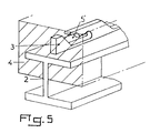
- FIG. 5 represents another alternative embodiment of the invention, in which the connection part 3 is in the form of a flat iron provided with cutouts 5 ′ with a reservation for housing and for holding a reinforcement element 1 and mounted on a profiled element 2 with an I or H section.
- the profiled element 2 is advantageously a commercial element and the connection part 3 can also be produced from a flat iron commercially available, possibly a large flat iron cut symmetrically to obtain two connection parts 3.
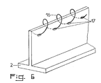
- FIG. 6 represents an alternative embodiment of the connection part 3, in which the profiled angle 15 is replaced by a helical element 16 cooperating with transverse bores 17 made in the core of the profiled element 2, near its free edge.
- a helical element 16 can easily be put in place in the bores 17, by simple screwing, and can be used simultaneously to hold reinforcing elements passing through its turns, possibly obliquely.
- Figures 7 and 8 of the accompanying drawings show other alternative embodiments of the connection part 3 of the profile according to Figure 6.
- Figure 7 shows a connection part 3 consisting of oblong holes 18 arranged at regular intervals near from the free end of the core of a T-shaped section or of an I or H shaped section cut symmetrically and extending parallel to this free edge or obliquely to the latter, the holes 18 of this part connection 3 cooperating with armatures 19 of corresponding section threaded into said holes 18.
- Such an embodiment makes it possible to obtain the same effects as those obtained with the profile according to FIG. 2.
- the profiled support 2 has a core cut so as to form appendages 20 having at least one latching part 21, these appendages 20 cooperating with transverse connection clips 22 having a cross section corresponding to the section of the appendices 20.
- This embodiment makes it possible to fix the clips 22 on the profiled supports 2 and to ensure their maintenance during the formwork and the pouring of the concrete, while immobilizing the transverse reinforcements in mortises 23, the clips 22 abutting on the opposite side against a tenon 24.
- FIG. 9 represents an alternative embodiment of the invention, in which the connection part 3 has a variable and discontinuous section over the length of the profiled support 2.
- a section can be obtained by deformation, hot or cold, at regular or irregular intervals, of the core of a profile, by rolling or forging.
- the core of the profile 2 has a reduced height allowing the passage of the transverse reinforcements and their support and a greater thickness corresponding to the deformation of the material, for example in the form of a bead 25 forming a connector for the concrete mass of the slab.
- connection part 3 can also be constituted by a twisted flat iron fixed by welding on another flat iron forming the support profile.
- Figure 10 shows an alternative embodiment of the device according to the invention, in which the ends of the support profile 2 are embedded in a drop 26 of the concrete slab 4, which is provided, in addition, in at least one edge longitudinal, a groove 27 for housing a piece 28 for resumption of cutting forces intended to cooperate with a corresponding groove in the adjacent slab.
- This embodiment makes it possible, on the one hand, by predicting the embedding of the ends of the profiled supports 2, to improve the connection between the slab and said profiles and to realize a prestressing of the latter, due to the withdrawal of the concrete, and, on the other hand, to stiffen the whole of the slab by torsion and therefore to facilitate handling, overturning, transport and operation in the service position, the fallout 26 forming, in addition, a land stop with or without a strike guard in the case of construction of bridges.
- the support profiles 2 may advantageously have a bending along their longitudinal axis.
- Such bending can easily, due to the very constitution of the profiled supports 2 in accordance with the invention, be carried out on site in a natural manner, by simple arrangement of their ends on supports, due to the low inertia of said profiles 2 obtained. thanks to the cutting, unlike conventional beams with I or H section which require factory bending, possibly hot.
- the bending of the profiles according to the invention can therefore be carried out in a particularly economical manner.
- Such bending allows, due to the molding of the devices according to the invention in the inverted position, to produce devices or slabs on flat, convex, concave, curved, left, and ... surfaces, in order to obtain a prestress said slabs along one or more preferred axes.
- the support profiles 2 and the reinforcements can advantageously be connected together on a preparation device annexed to the formwork and be put in place in the latter, before or after pouring the concrete, by sinking or by vibration.
- the junction between the various elements to be introduced into the concrete is carried out by clips or by ligatures.
- connection part 3 of the profiled supports 2 and / or the reinforcing elements 1, 7 or 19 can advantageously be made of a magnetic or magnetized material.
- connection between said sections and frames can be ensured in any position of the latter. relative to the formwork, without risking their fall in the latter during the pouring of the concrete.
- the device according to the invention advantageously consists of a mass of material in the form of concrete and a functional support formed by profiled supports, preferably of steel, connected to reinforcements also of steel, embedded in the mass of material, at by means of a connection part also made of steel and embedded in the mass of material.
- the mass of material could also consist of synthetic concrete cooperating with support elements and reinforcements of synthetic material or metal.
- connection part can easily be adapted over the entire length of the corresponding profile in order to respond exactly to the local stresses that this connection part must balance, for example by variation along the profile, according to the distribution of the effort.
- this geometry can also be constant for reasons of standardization, simplification of the calculations and implementation.
- the spacing of the profiles 2 is modular, as is the distance between the profiles 2 and the bottom of the formwork and the thickness of the device or slab obtained.
- Two successive sections 2 delimit between them a space in which the thickness of the device or slab can be identical or different from that of neighboring spaces by using the rheological characteristics of fresh concrete and the pressure drop that the space entails. free between profile 2 and the bottom of the mold.
- the device thus obtained can, therefore, present exactly and rationally the mechanical characteristics necessary for the absorption of the forces caused by external and internal actions, so as not to exceed the admissible values of each material.
- the external face of the device can advantageously be provided with a covering in ceramic tiles, in concrete slabs, in road carpets or in another floor covering.
- a covering in ceramic tiles, in concrete slabs, in road carpets or in another floor covering can fulfill the functions of formwork, wear layer, insulation layer. thermal or sound or sealing or cleanliness or decorative layer.
- the subject of the invention is also a method of turning this device over, characterized in that it consists in lifting this device by one or more profiles from its middle zone and, after passing vertically, retaining it by the profiles from its zones 'ends.
- Such an inversion mode makes it possible to guarantee, throughout the operation, the maintenance of the compression in the part of the device forming the concrete slab.
- the device according to the invention can be used, after hardening of the concrete, for the production of bridge decks, industrial floors or buildings, vertical structures, such as curtain walls, facades or noise barriers, or even roofing elements, or also for making pavements by laying a succession of adjacent devices on stringers or directly on a form layer by partial or total support of the profiles 2.
- the lightness of the device which can be obtained thanks to the invention, makes it possible to envisage, in particular in the case of the building, the production of elements of several square meters of surface which can easily be handled.
- mixed construction frees up a space between the ground and the concrete which can be used for the passage of networks, facilitating their installation, repair and replacement, and as a water reservoir structure facilitating drainage.
- the invention it is possible to produce prefabricated devices which can be used in particular in the field of public works and building, which can be quickly executed in the factory, in complete independence from atmospheric conditions, and of a perfect quality, the functional surface, namely that forming or supporting the wearing course, having a perfect surface finish, while the opposite surface, namely that forming the lower surface of the slab, remaining untreated.
- these devices can be produced repeatedly, so that their cost price can be considerably reduced, and, due to their total prefabrication, they can be transported, fully equipped with their superstructures, to the site where time intervention can also be significantly reduced, limiting discomfort to users and providing significant economic returns.
- the devices according to the invention make it possible to significantly reduce the quantity of steel in the beams, of the order of 15% to 20%, as well as to reduce the surfaces to be treated of the latter by around from 30% to 40%, which reduces maintenance costs by the same amount, while allowing, through both longitudinal and transverse reservations obtained, the passage of networks.
- the production method according to the invention makes it possible, owing to the very constitution of the connection part, to eliminate any prior bending of the support profiles in the factory, which also results in a reduction in the cost of these profiles.
Landscapes
- Engineering & Computer Science (AREA)
- Architecture (AREA)
- Structural Engineering (AREA)
- Chemical & Material Sciences (AREA)
- Civil Engineering (AREA)
- Composite Materials (AREA)
- Mechanical Engineering (AREA)
- Ceramic Engineering (AREA)
- Manufacturing & Machinery (AREA)
- Physics & Mathematics (AREA)
- Electromagnetism (AREA)
- Bridges Or Land Bridges (AREA)
- Transition And Organic Metals Composition Catalysts For Addition Polymerization (AREA)
- Medicines That Contain Protein Lipid Enzymes And Other Medicines (AREA)
- Manufacturing Of Tubular Articles Or Embedded Moulded Articles (AREA)
- Glass Compositions (AREA)
- Diaphragms For Electromechanical Transducers (AREA)
Claims (10)
- Vorrichtung, im wesentlichen bestehend aus einer Betonplatte (4), deren Armierung (1) mittels Verbindern (3) oder Verbindungsteilen mit Trägerprofilen (2) verbunden und teilweise in dem Beton (4) versenkt ist, wobei diese Vorrichtung bevorzugt in Überkopfstellung gegossen ist und jedes Trägerprofil (2) ein in dem Beton (4) versenktes Verbindungsteil (3) umfaßt, das einstückig mit dem Profil (2) ausgebildet ist und Mittel aufweist, die dazu bestimmt sind, mit den Armierungselementen (1) zusammenzuwirken, die querverlaufend zu den Profilen (2) befestigt und zusammen mit den Verhindern (3) der Profile (2) in dem Beton (4) versenkt sind, wobei das Verbindungsteil (3) einen gleichbleibenden Bereich aufweist und sich geradlinig auf dem Trägerprofil (2) und seinen Mitteln erstreckt, die dazu bestimmt sind, mit den Armierungselementen (1) zusammenzuwirken, die aus Ausschnitten (5) bestehen und die Triangulation des Profils (2) zwischen dem Gurt des Profils (2) und der Betonplatte (4) sowie eine Übertragung der vertikalen Lasten gewährleisten, wobei das Trägerprofil (2) in Form eines T-Profils ausgebildet ist, dessen das Verbindungsteil (3) bildender Steg mit gleichmäßig beabstandeten, im wesentlichen schwalbenschwanzförmig angeordneten Ausschnitten (5) versehen ist und das Profil (2) und sein Verbindungsteil (3) vorteilhafterweise entweder erhalten wird durch Ausschnitt im Steg eines T-Profils oder auch durch symmetrischen Ausschnitt eines I-oder H-Profils mit hohem Steg oder eines wiederhergestellten, geschweißten Profils, bestehend aus einem Gurt und einem Steg,
dadurch gekennzeichnet, daß
die äußeren, bevorzugt abgerundeten, die schwalbenschwanzförmigen Ausschnitte (5) begrenzenden Eckbereiche jeweils mit wenigstens einer Aussparung (6) zur Anbringung eines flachen Armierungselementes (7) oder eines oder mehrerer angebundener Armierungsrundeisen versehen sind. - Vorrichtung nach Anspruch 1, dadurch gekennzeichnet, daß die an den Eckbereichen der Ausschnitte (5) des Verbindungsteils (3) des Profils (2) vorgesehenen Aussparungen (6) mit einer biegsamen Armierung zusammenwirken, deren Kanten sich in die Aussparungen (6) einfügen.
- Vorrichtung nach Anspruch 1, dadurch gekennzeichnet, daß das Verbindungsteil (3) Querbohrungen (17) aufweist, die nahe an seiner freien Kante im Steg des Profilelementes (2) verlaufen und mit einem schraublinienförmigen Element (16) zusammenwirken, das mit den Armierungselementen (1) zusammenwirkt.
- Vorrichtung nach Anspruch 1, dadurch gekennzeichnet, daß das Verbindungsteil (3) Langlöcher (18) aufweist, die in gleichmäßigem Abstand nahe der freien Außenfläche des Steges angeordnet sind und sich parallel oder schräg zu dieser Kante erstrecken, wobei die Löcher (18) des Verbindungsteiles (3) mit Armierungen (19) des entsprechenden, in die Löcher (18) eingefädelten Abschnitts zusammenwirken.
- Vorrichtung nach Anspruch 1, dadurch gekennzeichnet, daß der Profilträger (2) einen Steg aufweist, der so ausgeschnitten ist, daß er Ansatzstücke (20) ausbildet, die zumindest einen Umklammerungsbereich (21) bilden, wobei die Ansatzstücke (20) mit Querverbindungsklammern (22) zusammenwirken, deren Querschnitt demjenigen der Ansatzstücke (20) entspricht, und diese Anordnung das verbindungsteil (3) bildet.
- Vorrichtung nach Anspruch 1, dadurch gekennzeichnet, daß das Verbindungsteil (3) in regel- oder unregelmäßigen Abständen auf der Länge des Steges des Profils (2) eine verringerte Höhe und eine wesentlichere Verdickung aufweist, je nach Verformung des Materials, beispielsweise in Form eines Flansches (25), der einen Verbinder für die Betonmasse der Platte bildet, wobei die Verformung warm oder kalt durch Walzen oder Schmieden erreicht wird.
- Vorrichtung nach einem der Ansprüche 1 bis 6, dadurch gekennzeichnet, daß die Trägerprofile (2) in vorteilhafter Weise entlang ihrer Längsachse gewölbt sind, um eine Vorspannung der Platten, bevorzugt direkt auf der Baustelle zu erhalten.
- Vorrichtung nach einem der Ansprüche 1 bis 7, dadurch gekennzeichnet, daß die Materialmasse aus einem synthetischen Beton besteht, der mit Träger- und Armierungselementen aus Kunststoff oder Metall zusammenwirkt.
- Vorrichtung nach einem der Ansprüche 1 bis 8, dadurch gekennzeichnet, daß ihre Außenseite in vorteilhafter Weise mit einer Straßenbelag-Abdeckung versehen ist.
- Verfahren zum Wenden der Vorrichtung nach einem der Ansprüche 1 bis 9, dadurch gekennzeichnet, daß es darin besteht, eine Vorrichtung mit einem oder mehreren Profilen an ihrem Mittelbereich hochzuheben und sie nach Übergang zur Vertikalen mit den Profilen ihrer Außenzone festzuhalten.
Applications Claiming Priority (6)
| Application Number | Priority Date | Filing Date | Title |
|---|---|---|---|
| FR8815199 | 1988-11-16 | ||
| FR8815199A FR2639056B1 (fr) | 1988-11-16 | 1988-11-16 | Dispositif utilise en genie civil, mecanique, outillage permettant la connexion d'une masse de matiere a un support fonctionnel |
| FR8903067A FR2643927B1 (fr) | 1989-03-06 | 1989-03-06 | Ossature mixte prefabriquee caracterisee par une construction pour retournement |
| FR8903067 | 1989-03-06 | ||
| FR8912940A FR2652600A2 (fr) | 1989-03-06 | 1989-09-29 | Ossature mixte prefabriquee caracterisee par une construction par retournement. |
| FR8912940 | 1989-09-29 |
Publications (2)
| Publication Number | Publication Date |
|---|---|
| EP0369914A1 EP0369914A1 (de) | 1990-05-23 |
| EP0369914B1 true EP0369914B1 (de) | 1994-08-17 |
Family
ID=27251731
Family Applications (1)
| Application Number | Title | Priority Date | Filing Date |
|---|---|---|---|
| EP89440125A Expired - Lifetime EP0369914B1 (de) | 1988-11-16 | 1989-11-16 | Verfahren zum Verbinden eines Matrixmaterials mit einem Funktionsträger und mit diesem Verfahren hergestellte Vorrichtungen |
Country Status (6)
| Country | Link |
|---|---|
| EP (1) | EP0369914B1 (de) |
| AT (1) | ATE110133T1 (de) |
| AU (1) | AU4637189A (de) |
| CA (1) | CA2003060A1 (de) |
| DE (1) | DE68917560T2 (de) |
| WO (1) | WO1990005818A1 (de) |
Cited By (1)
| Publication number | Priority date | Publication date | Assignee | Title |
|---|---|---|---|---|
| CN105220805A (zh) * | 2015-10-14 | 2016-01-06 | 山东隆和节能科技股份有限公司 | 钢筋桁架及预埋钢筋桁架的叠合板底板 |
Families Citing this family (10)
| Publication number | Priority date | Publication date | Assignee | Title |
|---|---|---|---|---|
| SE9003314L (sv) * | 1990-10-16 | 1992-04-17 | Bengt Johansson | Bjaelklagsbalk |
| FR2736667B1 (fr) * | 1995-07-13 | 1997-08-14 | Est Centre Tech Equip | Dispositif pour connecter l'ame d'un profile metallique au beton dans une construction mixte |
| ITCR990007A1 (it) * | 1999-07-07 | 2001-01-07 | Corrado Cavani | Solaio di copertura monolitico in calcestruzzo di cemento armato gettato in opera e relativo procedimneto di costruzione |
| DE102004001638A1 (de) * | 2004-01-10 | 2005-08-11 | Fritz, Bruno O., Dipl.-Ing. (FH) | Verfahren zur Herstellung eines Verbundelementes |
| FI6681U1 (fi) * | 2005-02-10 | 2005-05-17 | Juhani Maeki-Fossi | Palkki |
| DE102008011176A1 (de) * | 2008-02-26 | 2009-09-03 | Ssf-Ingenieure Gmbh | Stahl-Beton-Verbundträger und Verfahren zu seiner Herstellung |
| DE102010045453A1 (de) * | 2010-09-15 | 2012-03-15 | Ssf Ingenieure Ag | Brückenkonstruktion |
| AT517824B1 (de) * | 2015-09-21 | 2017-10-15 | Franz Oberndorfer Gmbh & Co Kg | Platte, insbesondere Boden- bzw. Deckenplatte für ein Bauwerk |
| US11028573B1 (en) * | 2020-01-16 | 2021-06-08 | Novel Structures, LLC | Serrated beam |
| US11725386B2 (en) | 2020-01-16 | 2023-08-15 | Simpson Strong-Tie Company Inc. | Serrated beam |
Family Cites Families (26)
| Publication number | Priority date | Publication date | Assignee | Title |
|---|---|---|---|---|
| FR742922A (de) * | 1933-03-18 | |||
| GB190901408A (en) * | 1909-01-20 | 1909-11-18 | Mark Fawcett | Improvements in Steel and Concrete Construction. |
| US1936147A (en) * | 1930-08-04 | 1933-11-21 | Leonie S Young | Floor or roof joist construction |
| GB396569A (en) * | 1931-09-17 | 1933-08-10 | Fritz Zollinger | Improvements in or relating to steel girders for concrete structures |
| FR41817E (fr) * | 1931-12-30 | 1933-04-21 | Brev De Construction S A Et | Poutrelle et son application à la constitution des planchers |
| US2028169A (en) * | 1934-07-09 | 1936-01-21 | Rolf K O Sahlberg | Composite beam |
| US2132220A (en) * | 1936-08-29 | 1938-10-04 | Eugene S Powers | Floor construction or the like |
| FR910506A (fr) * | 1945-05-07 | 1946-06-11 | Procédé de liaison intime entre profilés métalliques et dalles, voiles ou remplissages en tous matériaux tels que béton, béton armé ou aires portantes composites, planes ou voûtées | |
| US2636377A (en) * | 1945-11-07 | 1953-04-28 | Hilpert Meier George | Reinforced concrete beam |
| FR1008501A (fr) * | 1950-01-18 | 1952-05-19 | Seibert B | Poutres composées consistant en dalles de béton avec poutres métalliques |
| FR1092168A (fr) * | 1954-02-02 | 1955-04-19 | Poutrelle métallique légère | |
| CH410343A (de) * | 1961-10-23 | 1966-03-31 | Crompton Parkinson Ltd | Verbundbau-Konstruktion |
| US3401497A (en) * | 1964-02-26 | 1968-09-17 | Gregory Ind Inc | Support for reinforcing members |
| AU6409665A (en) * | 1966-09-16 | 1968-03-21 | Composite construction and shear connectors therefor | |
| US3576069A (en) * | 1969-05-23 | 1971-04-27 | Edward Augustus Proctor | Process for forming a composite building construction |
| DE2156016A1 (de) * | 1971-11-11 | 1973-05-17 | Dyckerhoff & Widmann Ag | Vorgefertigter stahlverbundtraeger |
| DE2218573A1 (de) * | 1972-04-17 | 1973-10-31 | Gerhard Dipl Ing Tuch | Verbundtraeger mit gezahnt-gestanzten obergurtprofil |
| DE2239572A1 (de) * | 1972-08-11 | 1974-02-21 | Gerhard Dipl Ing Tuch | Verbundtraeger mit gezahnter flanschauflagerung und hochgebogenen schubverduebelungen und stahlbetonplatten aus fertigteilen |
| BE795916A (fr) * | 1973-02-26 | 1973-06-18 | Noel Albert D G | Elements de construction mixtes 'acier-beton' |
| GB2053308B (en) * | 1979-07-06 | 1983-04-07 | Conder International Ltd | Beam floor or roof construction |
| US4493177A (en) * | 1981-11-25 | 1985-01-15 | Grossman Stanley J | Composite, pre-stressed structural member and method of forming same |
| US4495688A (en) * | 1983-09-07 | 1985-01-29 | Francois Longpre | Prefabricated concrete panel with truss |
| DE3503410A1 (de) * | 1984-02-07 | 1985-08-08 | Irmfried Dipl.-Ing. 7847 Badenweiler Brendel | Stahlverbundtraeger |
| FR2578276B1 (fr) * | 1985-03-01 | 1988-06-03 | Rech Etudes Tech | Element de construction en beton, notamment element de plancher, et procede pour sa fabrication |
| ATE59685T1 (de) * | 1985-09-17 | 1991-01-15 | Wolfhart Andrae | Verbundmittel fuer stahlbeton-verbundtragwerke. |
| DE8714517U1 (de) * | 1987-10-31 | 1987-12-10 | Kombi Tragwerk GmbH, 6277 Bad Camberg | Tragwerk |
-
1989
- 1989-11-15 CA CA002003060A patent/CA2003060A1/fr not_active Abandoned
- 1989-11-16 EP EP89440125A patent/EP0369914B1/de not_active Expired - Lifetime
- 1989-11-16 DE DE68917560T patent/DE68917560T2/de not_active Expired - Fee Related
- 1989-11-16 AT AT89440125T patent/ATE110133T1/de not_active IP Right Cessation
- 1989-11-16 AU AU46371/89A patent/AU4637189A/en not_active Abandoned
- 1989-11-16 WO PCT/FR1989/000589 patent/WO1990005818A1/fr not_active Ceased
Cited By (1)
| Publication number | Priority date | Publication date | Assignee | Title |
|---|---|---|---|---|
| CN105220805A (zh) * | 2015-10-14 | 2016-01-06 | 山东隆和节能科技股份有限公司 | 钢筋桁架及预埋钢筋桁架的叠合板底板 |
Also Published As
| Publication number | Publication date |
|---|---|
| CA2003060A1 (fr) | 1990-05-16 |
| DE68917560D1 (de) | 1994-09-22 |
| DE68917560T2 (de) | 1995-04-20 |
| WO1990005818A1 (fr) | 1990-05-31 |
| ATE110133T1 (de) | 1994-09-15 |
| AU4637189A (en) | 1990-06-12 |
| EP0369914A1 (de) | 1990-05-23 |
Similar Documents
| Publication | Publication Date | Title |
|---|---|---|
| EP0369914B1 (de) | Verfahren zum Verbinden eines Matrixmaterials mit einem Funktionsträger und mit diesem Verfahren hergestellte Vorrichtungen | |
| EP0288385B1 (de) | Vorgefertigtes Bauelement mit integrierter Wärmedämmung, insbesondere Deckenelement und Verfahren zu dessen Herstellung | |
| EP4194631A1 (de) | Vorgefertigte verbundfassadenplatte und verfahren zur herstellung einer fassade eines gebäudes | |
| EP2549028B1 (de) | Verfahren zur Herstellung eines gestützten Bauwerks und Gesamtheit der Schalungen für seine Erstellung | |
| FR2620153A1 (fr) | Panneau de construction, notamment panneau de bardage, a isolation thermique integree | |
| FR2973407A1 (fr) | Plaque mince en beton fibre comportant des moyens de liaison avec une piece en beton, et element de construction comportant une telle plaque mince | |
| EP3293318B1 (de) | Holz-beton-verbundstrukturen | |
| EP0004998A2 (de) | Baustruktur | |
| EP3070220B1 (de) | Verfahren zur behandlung von wärmebrücken | |
| FR2913993A1 (fr) | Entrevous en matrice minerale, dispositif de plancher a entrevous et son procede de realisation | |
| FR2925083A1 (fr) | Systeme d'assemblage de structures de batiments | |
| FR3057289B1 (fr) | Element de construction pour poutre mixe acier-beton arme, ensemble de construction et kits de construction | |
| EP3117054A1 (de) | Bewehrungsstab für ein strukturbauteil | |
| EP3320154B1 (de) | Bauteil und herstellungsverfahren eines solchen bauelements | |
| FR2757889A1 (fr) | Planchers realises a partir de dalles prefabriquees permettant de transmettre des efforts horizontaux sans dalle de compression rapportee sur chantier | |
| FR2812323A1 (fr) | Piscine du type composee d'elements prefabriques en beton arme | |
| EP2464798B1 (de) | Vorgefertigtes bauelement, zur vermeidung von wärmebrücken | |
| FR2738580A1 (fr) | Structure de tablier de pont et procede pour realiser le tablier | |
| EP0260197A1 (de) | Stahlbetonbrücke mit integrierter Schalung | |
| FR2843985A1 (fr) | Longeron de pont prefabrique | |
| FR2775998A1 (fr) | Procede de construction de batiments prefabriques et ensemble d'elements de construction pour la mise en oeuvre d'un tel procede | |
| FR2755451A1 (fr) | Nouveau procede de conception d'ouvrage en beton | |
| FR2781241A1 (fr) | Bloc de construction et procede de construction d'un edifice au moyen de tels blocs | |
| FR2595393A1 (fr) | Entrevous composite a base de polystyrene expanse | |
| BE517689A (de) |
Legal Events
| Date | Code | Title | Description |
|---|---|---|---|
| PUAI | Public reference made under article 153(3) epc to a published international application that has entered the european phase |
Free format text: ORIGINAL CODE: 0009012 |
|
| AK | Designated contracting states |
Kind code of ref document: A1 Designated state(s): AT BE CH DE ES FR GB GR IT LI LU NL SE |
|
| 17P | Request for examination filed |
Effective date: 19901015 |
|
| 17Q | First examination report despatched |
Effective date: 19910306 |
|
| GRAA | (expected) grant |
Free format text: ORIGINAL CODE: 0009210 |
|
| AK | Designated contracting states |
Kind code of ref document: B1 Designated state(s): AT BE CH DE ES FR GB GR IT LI LU NL SE |
|
| PG25 | Lapsed in a contracting state [announced via postgrant information from national office to epo] |
Ref country code: GB Effective date: 19940817 Ref country code: IT Free format text: LAPSE BECAUSE OF FAILURE TO SUBMIT A TRANSLATION OF THE DESCRIPTION OR TO PAY THE FEE WITHIN THE PRE;WARNING: LAPSES OF ITALIAN PATENTS WITH EFFECTIVE DATE BEFORE 2007 MAY HAVE OCCURRED AT ANY TIME BEFORE 2007. THE CORRECT EFFECTIVE DATE MAY BE DIFFERENT FROM THE ONE RECORDED.SCRIBED TIME-LIMIT Effective date: 19940817 Ref country code: AT Effective date: 19940817 Ref country code: NL Effective date: 19940817 Ref country code: ES Free format text: THE PATENT HAS BEEN ANNULLED BY A DECISION OF A NATIONAL AUTHORITY Effective date: 19940817 Ref country code: GR Free format text: LAPSE BECAUSE OF FAILURE TO SUBMIT A TRANSLATION OF THE DESCRIPTION OR TO PAY THE FEE WITHIN THE PRESCRIBED TIME-LIMIT Effective date: 19940817 |
|
| REF | Corresponds to: |
Ref document number: 110133 Country of ref document: AT Date of ref document: 19940915 Kind code of ref document: T |
|
| REF | Corresponds to: |
Ref document number: 68917560 Country of ref document: DE Date of ref document: 19940922 |
|
| PG25 | Lapsed in a contracting state [announced via postgrant information from national office to epo] |
Ref country code: SE Effective date: 19941117 |
|
| PG25 | Lapsed in a contracting state [announced via postgrant information from national office to epo] |
Ref country code: CH Effective date: 19941130 Ref country code: LI Effective date: 19941130 Ref country code: BE Effective date: 19941130 |
|
| NLV1 | Nl: lapsed or annulled due to failure to fulfill the requirements of art. 29p and 29m of the patents act | ||
| GBV | Gb: ep patent (uk) treated as always having been void in accordance with gb section 77(7)/1977 [no translation filed] |
Effective date: 19940817 |
|
| BERE | Be: lapsed |
Owner name: CENTRE D'ETUDES TECHNIQUES DE L'EQUIPEMENT DE L'E Effective date: 19941130 |
|
| PLBE | No opposition filed within time limit |
Free format text: ORIGINAL CODE: 0009261 |
|
| STAA | Information on the status of an ep patent application or granted ep patent |
Free format text: STATUS: NO OPPOSITION FILED WITHIN TIME LIMIT |
|
| REG | Reference to a national code |
Ref country code: CH Ref legal event code: PL |
|
| 26N | No opposition filed | ||
| PGFP | Annual fee paid to national office [announced via postgrant information from national office to epo] |
Ref country code: FR Payment date: 19981008 Year of fee payment: 10 |
|
| PGFP | Annual fee paid to national office [announced via postgrant information from national office to epo] |
Ref country code: LU Payment date: 19981126 Year of fee payment: 10 |
|
| PGFP | Annual fee paid to national office [announced via postgrant information from national office to epo] |
Ref country code: DE Payment date: 19981130 Year of fee payment: 10 |
|
| PG25 | Lapsed in a contracting state [announced via postgrant information from national office to epo] |
Ref country code: LU Free format text: LAPSE BECAUSE OF NON-PAYMENT OF DUE FEES Effective date: 19991116 |
|
| PG25 | Lapsed in a contracting state [announced via postgrant information from national office to epo] |
Ref country code: FR Free format text: LAPSE BECAUSE OF NON-PAYMENT OF DUE FEES Effective date: 20000731 |
|
| PG25 | Lapsed in a contracting state [announced via postgrant information from national office to epo] |
Ref country code: DE Free format text: LAPSE BECAUSE OF NON-PAYMENT OF DUE FEES Effective date: 20000901 |
|
| REG | Reference to a national code |
Ref country code: FR Ref legal event code: ST |