EP0370033B1 - Procede et dispositif d'analyse par micro-ondes - Google Patents
Procede et dispositif d'analyse par micro-ondes Download PDFInfo
- Publication number
- EP0370033B1 EP0370033B1 EP88905699A EP88905699A EP0370033B1 EP 0370033 B1 EP0370033 B1 EP 0370033B1 EP 88905699 A EP88905699 A EP 88905699A EP 88905699 A EP88905699 A EP 88905699A EP 0370033 B1 EP0370033 B1 EP 0370033B1
- Authority
- EP
- European Patent Office
- Prior art keywords
- microwave
- stark
- frequency
- absorption
- cell
- Prior art date
- Legal status (The legal status is an assumption and is not a legal conclusion. Google has not performed a legal analysis and makes no representation as to the accuracy of the status listed.)
- Expired - Lifetime
Links
Images

Classifications
-
- G—PHYSICS
- G01—MEASURING; TESTING
- G01N—INVESTIGATING OR ANALYSING MATERIALS BY DETERMINING THEIR CHEMICAL OR PHYSICAL PROPERTIES
- G01N22/00—Investigating or analysing materials by the use of microwaves or radio waves, i.e. electromagnetic waves with a wavelength of one millimetre or more
Definitions
- the invention relates to a method for analyzing gaseous media by means of microwave absorption, in particular for determining the concentration of gases, a microwave being generated with at least one frequency, and a device for analyzing gaseous media by means of the absorption of microwaves, in particular for determining the concentration, above all to carry out the method, with at least one microwave transmitter, at least one measuring cell, at least one detector, amplification and display devices for the measurement signal and a control device for the microwave transmitter.
- test procedure could only be used on a laboratory scale.
- Devices that could be used industrially were not available, since known devices were complex, both in terms of design, mechanical and electrical configurations, and in some cases had sensitive components, and compliance with critical parameters was problematic or complex.
- a stabilization and thus a regulation (in the true sense) of the frequency of the emitted microwave to the absorption maximum of the molecule of interest to be investigated possibly taking into account the Stark voltage acting on it, is necessary.
- microwave transmitter to transmit part of the microwave radiation through a reference cell with the component to be measured, a directional coupler again having to be used to split the microwave beams.
- the microwave transmitter is fixed on the absorption line of the component to be measured with the aid of the derivative signal at the detector of the reference cell which is required in addition to the detector of the measuring cell.
- the invention has for its object to provide a generic method that allows an inexpensive analysis of gaseous media, in particular the concentration determination using the disadvantages mentioned and creates the conditions for an industrially usable microwave analyzer.
- the above-mentioned object is achieved by a method of the type mentioned at the outset, which is characterized in that the microwave frequency within a predetermined bandwidth 2 ⁇ ⁇ continuously via the absorption frequency ⁇ o of the flow through the measuring cell 11 or in pure form in the reference cell 4 trapped gas is guided by a voltage ramp with the stroke 2 ⁇ ⁇ U.
- the course of the absorption of the microwave in the reference cell 4 is measured and the maximum absorption is determined and from this the tuning voltage U o is determined. Accordingly, the voltage ramp U o - ⁇ U ⁇ U ⁇ U o + ⁇ U is generated in the control device 63.
- the frequency-dependent course of the detector signal at the detector 19 of the measuring cell 11 is finally integrated with the signal amplification.
- the frequency range for sampling and integration is determined by a reference signal of a known clean gas component, which is included in a reference cell.
- a further embodiment provides that when the absorption line is split up using a Stark effect, a Stark AC voltage is applied, with the Stark AC voltage then being applied out of phase for the gas to be measured on the one hand and for the clean gas component present in the reference cell on the other hand, and in particular the Stark AC voltage is applied with a phase shift of 90 °.
- This may make it possible to provide only one preamplifier both for the reference signal and for the measurement signal, in particular the preamplification through a subcritically damped narrowband passive network.
- the Stark high voltage is supplemented by an inductance which directly supplements the Stark capacitance to form a parallel resonant circuit and forms the high voltage winding of a transformer.
- a preferred embodiment of the device according to the invention provides that the control device is designed for the continuous control of a frequency-determining voltage for the microwave transmitter over an adjustable frequency range and the detector is followed by an integrator for integrating the measurement signals during the change in the microwave frequency.
- the control device is designed for the continuous control of a frequency-determining voltage for the microwave transmitter over an adjustable frequency range and the detector is followed by an integrator for integrating the measurement signals during the change in the microwave frequency.
- at least one reference cell is assigned to the measuring cell in parallel, the detector of which is connected to the control device for the microwave transmitter, in particular at least one Stark generator being provided, which is the measuring and possibly the reference cell feeds a modulated Stark signal.
- microwave transmitters of different frequency ranges are assigned to a measuring cell, and in order to avoid replacing the clean gas generator, for example a permeation system in the reference cell, it can be provided in a further development that several reference cells one Are assigned to the measuring cell, with either the reference cells being connected in parallel to one another or in series, and in all cases being arranged in parallel in parallel with the measuring cell.
- the microwave transmitters which preferably have Gunn oscillators, are connected by a coupler on the one hand to the measuring cell and on the other hand to the reference cell (s), with a plurality of reference cells being able to be switched over by corresponding waveguide switches.
- the various components are measured by activating the respective transmitter and applying the respective Stark voltages, although switchover times may be necessary. Particularly when measuring two components, two transmitters are therefore preferably provided, which can be switched on via switches of the measuring cell.
- the configuration according to the invention has the particular advantage that only one Stark generator has to be used.
- lower-power microwave transmitters can be used, which are cheaper than powerful transmitters.
- thermostatting of the reference cell is not absolutely necessary, since it works with fully modulated rotation transitions.
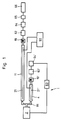
- the device 1 has a microwave transmitter 2, which is followed by the reference cell 4 and the measuring cell 11, arranged parallel to one another via the coupler 81.
- the measuring cell 11 is assigned to the detector 19 and the reference cell of the detector 19 '.
- 4 Stark electrodes 21, 21 ' are arranged, which are connected to a common Stark generator 61.
- the Stark field in the reference cell 4 is at least as large as that in the measuring cell 11.
- the mechanical structure of the device can correspond in detail to that of patent application DE 36 22 956.3 - with the parallel arrangement of measuring cells 11 and reference cell 4 via the coupler 81.
- the measuring cell 11, but also the reference cell 4 can be guided in a meandering manner to avoid large overall lengths and can be divided into several 180 degree arcs and straight Stark chamber areas.
- the cross section of the measuring cell and the reference cell is optimized for the respective microwave range in which the device is to operate and is matched to this, in particular if only one frequency is to be analyzed.
- the microwave transmitter preferably has a Gunn oscillator.
- the transmitters can be switched to corresponding measuring / reference cells via respective waveguide switches.
- the Stark voltages in the measuring or reference cell are switched on according to the transmitters.
- the respective component is provided purely for the reference cell, several reference cells behind the transmitters assigned to them are arranged in parallel with one another or all in a row, but overall in any case parallel to the measuring cell and according to the measurement to be taken.
- the Stark voltage supply is designed in such a way that it has an external inductance which expands the capacity of the inner Stark electrode to form a parallel resonant circuit, which in turn can simultaneously form the high-voltage winding of a transformer.
- Reference cell 4 and measuring cell 11 are tempered, and they can be kept at the same temperature.
- a constant pressure can be maintained in particular in the reference cell 4.
- a conventional vacuum pump is connected to the outlet of the reference cell 4.
- the outlet has a capillary through which a constant gas flow is achieved. If only one vacuum system is used, the capillary is followed by a filter which absorbs the component to be measured and thus prevents it from entering the measuring cell as a pure substance, where it would falsify the measurement.
- the pure substance required for the reference cell 4 is provided by a permeation vessel containing it, which has separate heating and / or cooling.
- a pressure control connected to a pressure sensor in the following way: If the suction power of a vacuum system varies, pressure fluctuations can occur despite the capillary. These are measured via the pressure sensor, which either heats the permeation vessel via the pressure control - if the pressure drops to achieve increased permeation of the pure component - or reduces or cools the heating - if the pressure rises so as to reduce the permeation capacity . This achieves precise and reliable pressure control, the pressure in the reference cell 4 corresponding at least to that of the measuring cell 11.
- the pressure in the reference cell 4 is selected to be higher than the pressure in the measuring cell 11. This generally also sets a higher strength in the reference cell 4. Field ahead to ensure complete modulation of the absorption line. In order to prevent crosstalk of the relatively large signals that are detected in the reference branch onto the measuring branch, there is a phase shift between strong alternating voltage in reference cell 4 and strong alternating voltage 900 in measuring cell 11.
- the detectors 19, 19 ' are each connected to its own preamplifier 62, 62' in the exemplary embodiment shown.
- Measuring or reference branch have their own preamplifiers 62 and 62 'and their own lock-in amplifiers 64 and 64'.
- the integrator 65 behind the lock-in amplifier 64 supplies a value which corresponds to a concentration of the measurement gas and is made visible via the display 66.
- the detectors 19, 19 'can in principle also be connected to a common preamplifier.
- the latter would presuppose that the Stark generator 61 supplies the two cells 4, 11 phase-shifted Stark voltages - preferably voltages shifted by 90 ° - so that the two measurement results of the detectors 19, 19 'can be worked out one after the other by the common preamplifier 62 .
- the preamplifier 62 is followed by the voltage of the reference cell detector 19, the lock-in amplifier 64 for controlling the microwave transmitter 2 via the control unit 63 and the lock-in amplifier 64 having an integrator, then the integrator 65 and finally the latter subsequent display 66.
- the microwave is divided via the coupler 81.
- Both cells 11, 4 work with the same Stark voltage, which effects the modulation of the rotation transitions, but as I said, with a phase difference of 90 °.
- the control can start at a, for example.
- the regulation generates an increasing voltage ramp; as soon as the absorption line ⁇ o is exceeded, which is caused by the reference signal (which is shown in FIG.
- the control voltage at the high-frequency transmitter 2 is reduced and thus the Absorption line scanned again.
- the limit is exceeded again, the control on the other side of the line switches over again and increases the voltage that is present at the oscillator.
- the signal at the detector 19 of the measuring cell 11 is integrated by the integrator 65 between the voltage deflection points.
- the integration value is a measure of the concentration of the gas in the measuring cell 11.
- the response time of the method is determined by the time it takes to scan over the line is required and is in the order of 30 to 60 seconds, which is sufficient in many cases.
- the amplifiers are phase selective. Measuring and reference signals which are shifted by 90 ° to one another can be separated into the measuring and reference branch of the circuit by means of a suitable phase position of the scanning times. This is done in that only the in-phase component in phase with the control voltage is rectified in each branch of the signal picked up by the detector, which contains reference and measuring components, while the component shifted by 90 ° lifts out.
- Phase shifts of the measurement and reference signals from the detector entering the lock-in amplifier relative to the Stark alternating voltages caused by electronic components can be taken into account by means of a digital phase shifter.
- an oscillator signal from which, for example, the frequency of the Stark voltage was derived by division, is fed to a counter, which is set to its preselected binary value by a set signal, for example that on which the Stark AC voltage is based.
- Output pulses occur at a time corresponding to the binary value after setting, which are converted in a known manner into a symmetrical wave now shifted by the desired phase at the frequency of the set signal. This wave then forms the control signal mentioned above.
- phase shift can be carried out in 200 steps of 1.8 °, for example.
- the phase shift can be switched on once and can also be reproduced automatically when a device is switched on again. It can be controlled directly by a computer.
- a frequency-determining bias voltage is obtained from the reference signal of the reference cell and fed to the oscillator. If due to the leakage of the microwave frequency from the absorption frequency and The control unit ensures a corresponding correction voltage so that a finite voltage arises in the reference branch from the zero crossing of the reference cell signal.
- the measurement signal can be displayed or used to control processes.
Landscapes
- Physics & Mathematics (AREA)
- Electromagnetism (AREA)
- Health & Medical Sciences (AREA)
- Life Sciences & Earth Sciences (AREA)
- Chemical & Material Sciences (AREA)
- Analytical Chemistry (AREA)
- Biochemistry (AREA)
- General Health & Medical Sciences (AREA)
- General Physics & Mathematics (AREA)
- Immunology (AREA)
- Pathology (AREA)
- Investigating Or Analysing Materials By Optical Means (AREA)
- Investigating Or Analyzing Materials By The Use Of Electric Means (AREA)
Abstract
Claims (10)
- Procédé d'analyse de milieux gazeux par absorption de micro-ondes et division de la courbe d'absorption par l'effet Stark, notamment pour déterminer la concentration de gaz, selon lequel au moins un émetteur de micro-ondes crée une micro-onde d'au moins une fréquence pour l'induire dans une cellule de référence contenant, à l'état pur, un gaz à déterminer et dans une cellule de mesure traversée par le gaz analysé, selon lequel :- la fréquence de l'émetteur à micro-ondes est conduite dans une largeur de bande prédéterminée 2 · Δν, en continu suivant la fréquence d'absorption νo du gaz traversant la cellule de mesure (11) ou du gaz à l'état pur contenu dans la cellule de référence (4), avec une rampe de tension d'excursion 2 · ΔU ;- on mesure la courbe de l'absorption des micro-ondes dans la cellule de référence (4) pendant la détermination à l'aide d'un détecteur (19′) et on détermine l'absorption maximale ;- avec l'absorption maximale on détermine la tension d'accord Uo et ainsi la fréquence d'absorption νo et on détermine la fréquence micro-ondes de νo - Δν jusqu'à νo + Δν par la rampe de tension fixée de Uo - ΔU jusqu'à Uo + ΔU ;- on mesure la courbe dépendant de la fréquence de l'absorption de la micro-onde dans la cellule de mesure (4) à l'aide d'un détecteur (19) et on intègre le signal de sortie après une préparation du signal (62, 64).
- Procédé selon la revendication 1, caractérisé en ce que les tensions alternatives Stark du gaz à mesurer et de la composante de gaz pur sont appliquées avec décalage d'un angle de phase prédéterminé.
- Procédé selon la revendication 2, caractérisé en ce que la détection de l'absorption dans la cellule de référence (4) et dans la cellule de mesure (11) est faite avec décalage de l'angle de phase entre les deux tensions alternatives Stark appliquées aux deux électrodes Stark (21, 21′).
- Procédé selon la revendication 1, caractérisé en ce qu'on règle la température d'un système de perméation convenant pour les micro-ondes, pour la composante de gaz pur pour maintenir constante la pression dans la cellule de référence (4).
- Dispositif d'analyse de milieux gazeux par absorption de micro-ondes, notamment pour déterminer la concentration et en particulier pour la mise en oeuvre du procédé selon l'une des revendications précédentes avec au moins un émetteur de micro-ondes (2), au moins une cellule de mesure (11), au moins un détecteur (19), des installations d'amplification (62, 64) et d'affichage (66) du signal de mesure ainsi qu'une installation de commande (63) de l'émetteur à micro-ondes (2), caractérisé en ce que- au moins une cellule de référence (4) est montée en parallèle à la cellule de mesure (11), son détecteur (19′) étant également relié par un amplificateur (62′, 64′) à l'installation de commande (63) de l'émetteur à micro-ondes (2) ;- l'installation de commande (63) de commande en continu d'une fréquence de l'émetteur à micro-ondes (2) crée la rampe de tension correspondante ;- un intégrateur (65) est prévu en aval du détecteur de la cellule de mesure (11) et de l'installation d'amplification (62, 64).
- Dispositif selon la revendication 5, caractérisé par au moins un générateur Stark (61) qui applique un signal Stark modulé en amplitude à la cellule de mesure ou le cas échéant à la cellule de référence (4, 11).
- Dispositif selon la revendication 6, caractérisé par un déphaseur pour créer une différence de phase entre la tension Stark pour la cellule de mesure et celle de la cellule de référence (11, 4).
- Dispositif selon la revendication 7, caractérisé en ce que les électroniques (62, 62′) en aval des deux détecteurs (19, 19′) sont accordées d'une part sur la phase du signal Stark fourni à la cellule de référence (4) et d'autre part sur la phase du signal Stark appliqué à la cellule de mesure (11).
- Dispositif selon la revendication 6, caractérisé en ce que l'alimentation pour fournir la tension alternative Stark à la cellule de mesure (11) et à la cellule de référence (4) est conçue pour avoir une inductance externe complétant la capacité de l'électrode Stark interne pour former un circuit oscillant parallèle, cette inductance constituant également l'enroulement de haute tension d'un transformateur.
- Dispositif selon l'une des revendications 5 à 8, caractérisé en ce que le ou les émetteur(s) micro-ondes (2) comportant chaque fois un ou des oscillateurs Gunn.
Applications Claiming Priority (3)
| Application Number | Priority Date | Filing Date | Title |
|---|---|---|---|
| DE19873723606 DE3723606A1 (de) | 1987-07-17 | 1987-07-17 | Verfahren und vorrichtung zur analyse mittels mikrowellen |
| DE3723606 | 1987-07-17 | ||
| PCT/DE1988/000431 WO1989000684A1 (fr) | 1987-07-17 | 1988-07-08 | Procede et dispositif d'analyse par micro-ondes |
Publications (2)
| Publication Number | Publication Date |
|---|---|
| EP0370033A1 EP0370033A1 (fr) | 1990-05-30 |
| EP0370033B1 true EP0370033B1 (fr) | 1995-11-02 |
Family
ID=6331742
Family Applications (1)
| Application Number | Title | Priority Date | Filing Date |
|---|---|---|---|
| EP88905699A Expired - Lifetime EP0370033B1 (fr) | 1987-07-17 | 1988-07-08 | Procede et dispositif d'analyse par micro-ondes |
Country Status (5)
| Country | Link |
|---|---|
| US (1) | US4972699A (fr) |
| EP (1) | EP0370033B1 (fr) |
| JP (1) | JP2682546B2 (fr) |
| DE (1) | DE3723606A1 (fr) |
| WO (1) | WO1989000684A1 (fr) |
Families Citing this family (13)
| Publication number | Priority date | Publication date | Assignee | Title |
|---|---|---|---|---|
| DE3929079A1 (de) * | 1989-09-01 | 1991-03-21 | Dreizler Helmut | Verfahren und vorrichtung zur analyse gasfoermiger medien mittels mikrowellen |
| DE4113296A1 (de) * | 1991-04-24 | 1992-10-29 | Fritz Stahlecker | Verfahren zum blockweisen wechseln von kannen an einer spinnmaschine und spinnmaschine |
| GB2273986B (en) * | 1992-12-29 | 1996-11-13 | Univ Wales Medicine | Microwave spectrometers |
| DE19603905C1 (de) * | 1996-02-03 | 1997-03-20 | Karlsruhe Forschzent | Mikrowellenhohlraumresonator für die kontinuierliche, spektroskopische Gasanalyse |
| US5949237A (en) * | 1996-02-03 | 1999-09-07 | Forschungszentrum Karlsruhe Gmbh | Microwave cavity resonator for continuous spectroscopic gas analysis |
| WO2001020311A1 (fr) * | 1999-09-17 | 2001-03-22 | Sik - Institut För Livsmedel Och Bioteknik Ab | Dispositif et procede de detection de corps etrangers dans des produits |
| GB2367360A (en) * | 2000-05-01 | 2002-04-03 | Datex Ohmeda Inc | Microwave acoustic gas analyser |
| US7520667B2 (en) * | 2006-05-11 | 2009-04-21 | John Bean Technologies Ab | Method and system for determining process parameters |
| US9325334B2 (en) * | 2013-06-12 | 2016-04-26 | Texas Instruments Incorporated | IC, process, device generating frequency reference from RF gas absorption |
| US9128023B2 (en) * | 2013-05-23 | 2015-09-08 | Texas Instruments Incorporated | Calibration scheme for gas absorption spectra detection |
| US9429528B2 (en) * | 2013-05-23 | 2016-08-30 | Texas Instruments Incorporated | Determining gas absorption line from separate and alternating RF signals |
| US20140373599A1 (en) * | 2013-06-25 | 2014-12-25 | Texas Instruments Incorporated | Detection and locking to the absorption spectra of gasses using quartz enhanced photoacoustic sprectroscopy |
| US10448864B1 (en) | 2017-02-24 | 2019-10-22 | Nokomis, Inc. | Apparatus and method to identify and measure gas concentrations |
Family Cites Families (7)
| Publication number | Priority date | Publication date | Assignee | Title |
|---|---|---|---|---|
| US2792548A (en) * | 1945-05-28 | 1957-05-14 | Rca Corp | Systems and methods of gas analysis |
| US3696292A (en) * | 1970-08-03 | 1972-10-03 | Beloit Corp | Microwave moisture sensing system including means to continuously change the transmission path of the microwave energy |
| JPS5040000A (fr) * | 1973-08-15 | 1975-04-12 | ||
| JPS5544904B2 (fr) * | 1973-09-05 | 1980-11-14 | ||
| JPH0227617B2 (ja) * | 1981-05-29 | 1990-06-19 | Sagami Chem Res | Nijuhenchomaikuroharenzokubunsekihohooyobisochi |
| US4607521A (en) * | 1984-11-20 | 1986-08-26 | Sagami Chemical Research Center | Method of improving response characteristics of gas sensor using microwave spectrometer |
| DE3622957A1 (de) * | 1986-07-09 | 1988-02-11 | Kernforschungsz Karlsruhe | Verfahren und vorrichtung zur analyse mittels mikrowellen |
-
1987
- 1987-07-17 DE DE19873723606 patent/DE3723606A1/de active Granted
-
1988
- 1988-07-08 JP JP63505696A patent/JP2682546B2/ja not_active Expired - Lifetime
- 1988-07-08 EP EP88905699A patent/EP0370033B1/fr not_active Expired - Lifetime
- 1988-07-08 WO PCT/DE1988/000431 patent/WO1989000684A1/fr not_active Ceased
- 1988-07-08 US US07/327,808 patent/US4972699A/en not_active Expired - Fee Related
Non-Patent Citations (1)
| Title |
|---|
| Instruments and Experimental Techniques, Band 17, Nr. 3, Teil II, Mai/Juni 1974, Consultants Bureau, Plenum Publishing Corp., (New York, US), A.A. Dem'yanov et al.: "Measurement of the complex permittivity of strongly absorptive liquids", Seiten 777-778 siehe Abbildung 1 * |
Also Published As
| Publication number | Publication date |
|---|---|
| EP0370033A1 (fr) | 1990-05-30 |
| DE3723606C2 (fr) | 1993-01-28 |
| JP2682546B2 (ja) | 1997-11-26 |
| DE3723606A1 (de) | 1989-01-26 |
| WO1989000684A1 (fr) | 1989-01-26 |
| US4972699A (en) | 1990-11-27 |
| JPH01502363A (ja) | 1989-08-17 |
Similar Documents
| Publication | Publication Date | Title |
|---|---|---|
| EP0370033B1 (fr) | Procede et dispositif d'analyse par micro-ondes | |
| DE3627608A1 (de) | Messvorrichtung fuer mikrowellen-rauschen | |
| DE4437575C2 (de) | Spektrometer mit kohärenter und periodisch gepulster Strahlung | |
| DE2727976A1 (de) | Verfahren zum bestimmen des partialdruckes und der konzentration eines gases und schaltungsanordnung zum durchfuehren des verfahrens | |
| EP3201604A1 (fr) | Procédé et analyseur de gaz pour mesurer la concentration d'un constituant gazeux dans un gaz de mesure | |
| DE3929079C2 (fr) | ||
| WO1990015340A1 (fr) | Procede et dispositif d'analyse spectrale rapide de signaux en un ou plusieurs points de mesure | |
| DE60311182T2 (de) | Laserspektroskopie mittels einer Master-Slave-Steuerungsarchitektur | |
| EP0252235B1 (fr) | Méthode et dispositif pour l'analyse par micro-ondes | |
| DE1673247C3 (de) | Spektrometer für gyromagnetische Resonanz mit wählbaren internen und externen Resonanzkontrollsubstanzen | |
| DE1299444B (de) | Vorrichtung zum Messen gyromagnetischer Resonanzsignale | |
| DE10238356A1 (de) | Quantitative spektroskopische Bestimmung eines Absorbers | |
| DE19628310C2 (de) | Optischer Gasanalysator | |
| EP1066534B1 (fr) | Analyseur vectoriel de reseau | |
| EP0629851A2 (fr) | Dispositif pour analyse de traces de gaz par spectroscopie d'absorption | |
| DE2945172A1 (de) | Verfahren und geraet zur bestimmung der konzentration eines gases in einem gasgemisch, insbesondere des kohlendioxidgehaltes | |
| DE3137660A1 (de) | Verfahren und vorrichtung zur messung des konzentrationsverhaeltnisses zweier ir-, nir-, vis- oder uv-strahlung absorbierender komponenten eines komponentengemischs | |
| EP3417299B1 (fr) | Analyseur de spectre et procédé d'analyse spectrale | |
| EP0310816A1 (fr) | Poursuite automatique de fréquence dans un procédé mesureur de rayons corpusculaires utilisant un rayon primaire modulé | |
| DE2352315B1 (de) | Verfahren zur Stabilisierung des Verhaeltnisses von Messfrequenz zu Magnetfeldstaerke bei einem Spinresonanzspektrometer | |
| EP3575759B1 (fr) | Spectromètre et son procédé de fonctionnement | |
| DE10120568A1 (de) | Akustischer Mikrowellen-Gasanalysator | |
| DE2953958C2 (de) | Gerät zum Erfassen und Sammeln von mit verschiedenen Frequenzen ausgestrahlten Funksignalen in einer Station | |
| DE2939172C2 (de) | Verfahren zur Messung und Nachregelung der Frequenzlinearität von elektronisch durchstimmbaren Wobbeloszillatoren | |
| DE19654740A1 (de) | Meßverfahren zur Vierpolanalyse mit hoher Bandbreite |
Legal Events
| Date | Code | Title | Description |
|---|---|---|---|
| PUAI | Public reference made under article 153(3) epc to a published international application that has entered the european phase |
Free format text: ORIGINAL CODE: 0009012 |
|
| 17P | Request for examination filed |
Effective date: 19890519 |
|
| AK | Designated contracting states |
Kind code of ref document: A1 Designated state(s): AT BE CH DE FR GB IT LI LU NL SE |
|
| RBV | Designated contracting states (corrected) |
Designated state(s): BE CH FR GB IT LI NL SE |
|
| REG | Reference to a national code |
Ref country code: DE Ref legal event code: 8566 |
|
| RAP1 | Party data changed (applicant data changed or rights of an application transferred) |
Owner name: KERNFORSCHUNGSZENTRUM KARLSRUHE GMBH |
|
| 17Q | First examination report despatched |
Effective date: 19950113 |
|
| RAP1 | Party data changed (applicant data changed or rights of an application transferred) |
Owner name: FORSCHUNGSZENTRUM KARLSRUHE GMBH |
|
| ITF | It: translation for a ep patent filed | ||
| GRAA | (expected) grant |
Free format text: ORIGINAL CODE: 0009210 |
|
| AK | Designated contracting states |
Kind code of ref document: B1 Designated state(s): BE CH FR GB IT LI NL SE |
|
| ET | Fr: translation filed | ||
| REG | Reference to a national code |
Ref country code: CH Ref legal event code: NV Representative=s name: ROTTMANN, ZIMMERMANN + PARTNER AG |
|
| GBT | Gb: translation of ep patent filed (gb section 77(6)(a)/1977) |
Effective date: 19960217 |
|
| PGFP | Annual fee paid to national office [announced via postgrant information from national office to epo] |
Ref country code: CH Payment date: 19960701 Year of fee payment: 9 |
|
| PGFP | Annual fee paid to national office [announced via postgrant information from national office to epo] |
Ref country code: SE Payment date: 19960716 Year of fee payment: 9 |
|
| PGFP | Annual fee paid to national office [announced via postgrant information from national office to epo] |
Ref country code: BE Payment date: 19960717 Year of fee payment: 9 |
|
| PGFP | Annual fee paid to national office [announced via postgrant information from national office to epo] |
Ref country code: FR Payment date: 19960730 Year of fee payment: 9 |
|
| PGFP | Annual fee paid to national office [announced via postgrant information from national office to epo] |
Ref country code: NL Payment date: 19960731 Year of fee payment: 9 |
|
| PLBE | No opposition filed within time limit |
Free format text: ORIGINAL CODE: 0009261 |
|
| STAA | Information on the status of an ep patent application or granted ep patent |
Free format text: STATUS: NO OPPOSITION FILED WITHIN TIME LIMIT |
|
| 26N | No opposition filed | ||
| PGFP | Annual fee paid to national office [announced via postgrant information from national office to epo] |
Ref country code: GB Payment date: 19970415 Year of fee payment: 10 |
|
| PG25 | Lapsed in a contracting state [announced via postgrant information from national office to epo] |
Ref country code: SE Effective date: 19970709 |
|
| PG25 | Lapsed in a contracting state [announced via postgrant information from national office to epo] |
Ref country code: LI Free format text: LAPSE BECAUSE OF NON-PAYMENT OF DUE FEES Effective date: 19970731 Ref country code: CH Free format text: LAPSE BECAUSE OF NON-PAYMENT OF DUE FEES Effective date: 19970731 Ref country code: BE Free format text: LAPSE BECAUSE OF NON-PAYMENT OF DUE FEES Effective date: 19970731 |
|
| BERE | Be: lapsed |
Owner name: FORSCHUNGSZENTRUM KARLSRUHE G.M.B.H. Effective date: 19970731 |
|
| PG25 | Lapsed in a contracting state [announced via postgrant information from national office to epo] |
Ref country code: NL Free format text: LAPSE BECAUSE OF NON-PAYMENT OF DUE FEES Effective date: 19980201 |
|
| REG | Reference to a national code |
Ref country code: CH Ref legal event code: PL |
|
| PG25 | Lapsed in a contracting state [announced via postgrant information from national office to epo] |
Ref country code: FR Free format text: LAPSE BECAUSE OF NON-PAYMENT OF DUE FEES Effective date: 19980331 |
|
| NLV4 | Nl: lapsed or anulled due to non-payment of the annual fee |
Effective date: 19980201 |
|
| EUG | Se: european patent has lapsed |
Ref document number: 88905699.0 |
|
| REG | Reference to a national code |
Ref country code: FR Ref legal event code: ST |
|
| PG25 | Lapsed in a contracting state [announced via postgrant information from national office to epo] |
Ref country code: GB Free format text: LAPSE BECAUSE OF NON-PAYMENT OF DUE FEES Effective date: 19980708 |
|
| GBPC | Gb: european patent ceased through non-payment of renewal fee |
Effective date: 19980708 |
|
| PG25 | Lapsed in a contracting state [announced via postgrant information from national office to epo] |
Ref country code: IT Free format text: LAPSE BECAUSE OF NON-PAYMENT OF DUE FEES;WARNING: LAPSES OF ITALIAN PATENTS WITH EFFECTIVE DATE BEFORE 2007 MAY HAVE OCCURRED AT ANY TIME BEFORE 2007. THE CORRECT EFFECTIVE DATE MAY BE DIFFERENT FROM THE ONE RECORDED. Effective date: 20050708 |