EP0629851A2 - Dispositif pour analyse de traces de gaz par spectroscopie d'absorption - Google Patents
Dispositif pour analyse de traces de gaz par spectroscopie d'absorption Download PDFInfo
- Publication number
- EP0629851A2 EP0629851A2 EP94109051A EP94109051A EP0629851A2 EP 0629851 A2 EP0629851 A2 EP 0629851A2 EP 94109051 A EP94109051 A EP 94109051A EP 94109051 A EP94109051 A EP 94109051A EP 0629851 A2 EP0629851 A2 EP 0629851A2
- Authority
- EP
- European Patent Office
- Prior art keywords
- signal
- measurement
- measuring
- laser
- phase
- Prior art date
- Legal status (The legal status is an assumption and is not a legal conclusion. Google has not performed a legal analysis and makes no representation as to the accuracy of the status listed.)
- Withdrawn
Links
Images


Classifications
-
- G—PHYSICS
- G01—MEASURING; TESTING
- G01N—INVESTIGATING OR ANALYSING MATERIALS BY DETERMINING THEIR CHEMICAL OR PHYSICAL PROPERTIES
- G01N21/00—Investigating or analysing materials by the use of optical means, i.e. using sub-millimetre waves, infrared, visible or ultraviolet light
- G01N21/17—Systems in which incident light is modified in accordance with the properties of the material investigated
- G01N21/25—Colour; Spectral properties, i.e. comparison of effect of material on the light at two or more different wavelengths or wavelength bands
- G01N21/31—Investigating relative effect of material at wavelengths characteristic of specific elements or molecules, e.g. atomic absorption spectrometry
- G01N21/39—Investigating relative effect of material at wavelengths characteristic of specific elements or molecules, e.g. atomic absorption spectrometry using tunable lasers
Definitions
- the invention relates to a device for absorption spectroscopic trace gas analysis.
- the invention relates to an arrangement and a method for the power supply of a measuring laser, namely a diode laser for use in absorption spectroscopic trace gas analysis, a device for modulation and demodulation with an arrangement and a method for evaluating a measuring signal according to magnitude and phase in relation to a reference signal , An arrangement and a method for drift correction of discrete-time measurement signals based on a reference signal also for absorption spectroscopic trace gas analysis, a device for determining and normalizing the intensity of a measurement signal with an associated method for use in modulation laser absorption spectroscopy, as well as an arrangement and a method for alternating sample and background measurement.
- Diode lasers around the near and middle infrared are mainly used in spectroscopic trace gas analysis.
- the power supply of the diode laser used is essential for the stability of the measuring system and for its sensitivity.
- an additional current ramp is superimposed on a direct current for supplying the laser, which adjusts the laser emission with the ramp frequency in proportion to the ramp stroke in the frequency range.
- a further increase in sensitivity can also be achieved using a modulation technique, for example amplitude or frequency modulation.
- the absorption measurement signal is generated by the relative position of the laser and absorption line. Since the laser sweeps over an absorption line over time, a signal curve over time is obtained which depends on the shape of the absorption line and the respective detection technique.
- PS-US 5 103 453 it is proposed according to PS-US 5 103 453 to perform a power control of the diode laser power supply, the first and second harmonics of a detector signal being used for power control.
- this requires an extremely complex power supply with a bandwidth of approx. 200 to 700 Hz, which means that the advantages that are partially offset by the optical heating of the diode laser for modulation thereof are canceled out.
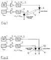
- a single-tone or one-tone modulation technique in which an oscillator 501 has a fixed or variable, i.e. H. tunable frequency generated, which is available via an amplifier 502 as modulation signal M.
- a signal part S is coupled out via a coupler 503 in order to be available as a reference signal for a phase-sensitive detection via a further amplifier 504.
- the modulation signal M is a coupling element 505 a transmitter, z. B. supplied to a laser diode, which emits a modulated signal that arrives on a transmission path and interacts with a sample.
- the modulated signal penetrating the sample then reaches a receiver and is supplied to the phase detector 507 as a detector signal D via an amplifier 506.
- the phase detector 507 consists of an adjustable phase shifter 571, a mixer 572, an amplifier 573 and a further amplifier 574.
- the detector output signal reaches the input of the amplifier 573 and is fed to the mixer 572.
- the mixer 572 also receives a signal from the adjustable phase shifter 571, to which the signal S or T is present for phase-sensitive detection.
- a measurement signal CH1 is then available at the output of the amplifier 574.
- the modulation can take place in the two-tone or two-tone technique already mentioned, in that two discrete frequencies from the oscillators 508 and 509 are mixed using the mixer 510 and provided as a modulation signal M via an amplifier 511 .
- the signal originating from the oscillator 509 in the example is subjected to a frequency doubling 513 via a coupling element 512 and fed to the phase-sensitive detector 507 as signal T via a further amplifier 514.
- the modulation signal M according to FIG. 508 is shown as a sum and as a difference of the frequencies from the oscillators 508 and 509.
- either the one-tone technique or the two-tone technique can be used.
- commercial lock-in amplifiers are not available for the required frequency range (Mhz - Ghz).
- a lock-in amplifier for use in laser spectroscopy has hitherto been constructed on the basis of the hardware available and in view of the specific measurement task in such a way that only one of the two methods mentioned above could be implemented in each case. Therefore, there is a high outlay in the case of changed measurement tasks, since a corresponding change in the experimental setup or the evaluation electronics is necessary. In particular, it is not possible to use the different methods for optimizing the measurement result alternately or simultaneously in a two-channel test setup with a separate measurement and reference channel.
- Interference signals that are contained in the current ramp for tuning the laser are particularly critical. These interference signals can be periodic or discrete in nature. In this case, even at low interference amplitudes, frequencies occur that are lower than the actual ramp frequency with an otherwise stable signal for shifting the measurement signal per scan. If one now averages over a larger number of scans or spectra shifted in this way, there is also an undesired shift relative to the undisturbed mean spectrum for the averaged spectrum.
- a calibration or reference signal of known concentration is required.
- This calibration or reference signal is generated by filling a measuring cell with a calibration gas of known concentration and introducing this measuring cell into the absorptio-skeptroscopic beam path of the measuring system.
- the spectrum of the calibration gas measured here is stored as a calibration or reference signal for comparison purposes.
- An evaluation unit calculates the amplitude ratio of the current measurement spectrum or scan to the calibration or reference signal of the calibration gas, for example using a regression method.
- the measurement signal calculated with known evaluation algorithms is highly error-prone. Even when using conventional averaging, the above-mentioned shift results for the averaged spectrum relative to the undisturbed mean value spectrum, so that measurement errors occur.
- a change in the calculated concentration value c can be caused by a change in the absorption difference ⁇ I, but also by a change in the original intensity I0, or can be attributed to these variables.
- a basic arrangement for carrying out such a method is shown in FIG. 15. 15, the diode laser 602 is controlled via a control unit 601 for the temperature or the current in the pn junction.
- a beam splitter 603 is arranged on the output side of the diode laser 602 and is connected to a reference detector 605 via suitable deflection elements 604.
- the beam splitter 603, the deflection elements 604 and the reference detector 605 form a control channel 606.
- the output signal of the diode laser 602 After passing through the beam splitter 603, the output signal of the diode laser 602 enters an absorption measuring cell 607 with length 1.
- the medium to be examined is located in the absorption measuring cell 607.
- the radiation from the diode laser 602 interacts with the medium to be examined in the absorption measuring cell 607 in the manner described above.
- the absorption measuring cell 607 is connected to a measuring detector 608.
- the measurement signal is determined by means of the measurement detector 608 and a downstream evaluation circuit 609.
- the original intensity values I0 determined via the reference detector 605 run into a signal processing device 610 and are used there together with the output signal of the evaluation circuit 609 to determine the concentration of the medium in the absorption measuring cell 607.
- the absorption measuring cell 607 must be exchanged for a calibration measuring cell in time-division multiplexing, or the measuring gas must be removed from the beam path within the absorption measuring cell 607.
- this is disadvantageous in particular in the case of automatic measurements or measurements over a longer period of time because of the necessary interventions in the entire measuring arrangement.
- the switchover between sample and background measurement in the spectroscopic trace gas analysis takes place by exchanging the sample air after a measuring time t0 to t1 with the sample-free zero air mentioned.
- the exchange time t1 to t2 depends on the most varied constructive parameters of the measuring cell arrangement including the construction of gas inlet and outlet, the measuring cell volume, the measuring cell geometry and the properties of the gas and the pumping power.
- One difficulty in determining the correct concentration is determining whether a significant signal drift has occurred due to the time offset or time delay between the sample and background measurements. If such a signal drift has been detected, the necessary relationship between the measurements is no longer guaranteed. This results in the need to carry out the sample measurement, gas exchange and background measurement in the shortest possible time, usually repeated cyclically.
- the object of the invention to propose a complex device for absorption spectroscopic trace gas analysis, with which it is possible, on the one hand, to effectively propose a laser power supply that signals obtained after passing through a measuring or reference cell using different Modulation techniques can be evaluated, furthermore a drift correction can be implemented in such a way that the otherwise necessary storage of a large number of raw spectra can be dispensed with and that there is a dynamic standardization possibility. Furthermore, a sample and background measurement should alternately be realized in a non-mechanical way.
- a method and an arrangement for the power supply of a measuring laser, in particular a diode laser for absorption spectroscopic trace gas analysis is to be specified which leads to as little interference as possible to the diode laser and which is able, in cooperation with optical modulation or optical tuning of the diode laser, to achieve a stable one To enable laser operation or a measuring system equipped with it.
- a method and an arrangement for evaluating a measurement signal according to magnitude and phase with respect to a reference signal is to be specified, which in particular enables modulation and phase-sensitive demodulation of a signal for absorption spectroscopic examinations, for example trace gases, such that simultaneous operation of different Modulation techniques in different measuring channels is possible.
- Another object of the invention is to provide a method and an arrangement for determining and normalizing the intensity of a measurement signal in modulation laser absorption spectroscopy or interferometry, with which or which, when using only a single measurement detector, the original intensity I0 des Diode laser, including the influence of undesirable changes in the beam path of the arrangement, can be reliably detected and, on the basis thereof, a dynamic normalization of the intensities to obtain an error-free, highly accurate measurement signal can be carried out or achieved.
- another part of the invention is to provide a method and an arrangement for alternating sample and background measurement for selective trace gas analysis, which allows an extreme shortening of the cycle or cycles between sample and background measurement. This is to ensure that, on the one hand, the influence of drifts on the measurement accuracy is reduced and, on the other hand, the accuracy and time resolution when determining properties of trace gases is increased.
- a first basic idea of the invention is to use a diode laser power supply output stage with an extremely small bandwidth, with a complete electrical separation between the direct current diode laser power supply and a tuning signal implemented optically in the diode laser, e.g. B. a ramp signal or a sine or pulse signal is provided.
- the laser power supply is advantageously designed as a constant current source.
- the optical imaging and the supply of a defined amount of heat take place directly in the region of the pn-junction of the diode laser.
- the image can be done using a mirror or lens system.
- the laser diode or light source provided for optical tuning being arranged in the immediate vicinity of the pn junction of the actual diode laser.
- a second basic idea of the invention is to propose a method and an arrangement which enables simultaneous operation of the one-tone and two-tone technology in the modulation or demodulation, for example of the signal of a diode laser, for use in spectroscopy, as a result of which the evaluation of a measurement signal is simplified and a flexible optimal adaptation to experimental conditions, such as. B. laser noise characteristics, background structures, etc. is guaranteed. Due to the high modulation frequencies up to the megahertz and gigahertz range that can be achieved with the method according to the invention and the associated arrangement, it can be used both in rapidly tuned continuous-wave (cw) systems and in pulsed systems of laser spectroscopy, thereby increasing the overall time resolution the respective measurement task can be implemented.
- cw continuous-wave
- Broadband detectors are expediently used for this purpose on the receiver side.
- typical measurement tasks e.g. B. the simultaneous operation of different modulation techniques in the measurement and reference channel can be fulfilled. This is of particular importance since the one-tone and the two-tone technology not only generate different signal forms, but are also influenced differently by interference. Since both techniques can be selected and combined with the inherent advantages, the overall system can be adapted depending on the current operating conditions.
- two different frequencies ⁇ 1 and ⁇ 2 are mixed with the aid of a mixer for the sum ⁇ 1 + ⁇ 2 and for the difference ⁇ 1 - ⁇ 2.
- the mixed signal is available as a modulation signal M after appropriate level adjustment and filtering that may become necessary.
- Part of this modulation signal M is coupled out via a coupler and after suitable filtering and signal conditioning either in the form of ⁇ 1 + ⁇ 2 or in the form of ⁇ 1 - ⁇ 2 as a one-tone detection signal S for operating a demodulation part with a phase-sensitive detector or for triggering the lock -In-amplifier provided in the demodulation section.
- one of the two fundamental frequencies ⁇ 1 or ⁇ 2 is coupled out and level-adjusted after frequency doubling and, if necessary, filtered.
- the two-tone detection signal T obtained in this way is then fed to a demodulation part analogously to the one-tone detection signal S.
- the coupler used provides an automatic automatic coupling of the modulation signal M to the one-tone detection signal S and to the two-tone detection signal T regardless of the type which frequency is currently being varied a.
- a second embodiment of the arrangement according to the invention it is proposed to combine two separately generated modulation frequencies ⁇ 1 and ⁇ 2 with the aid of a combination element to form the modulation signal M, which now consists of the two original, original frequencies ⁇ 1 and ⁇ 2.
- This has the advantage that no higher harmonic interference components arise in the modulation signal M itself and that no secondary sensitivity points are noticeable in the evaluation of the measurement signal.
- components are coupled out of the two frequencies ⁇ 1 and ⁇ 2 and fed to a mixer.
- a difference signal ⁇ 1 - ⁇ 2 is expediently provided for two-tone detection, ie a two-tone detection signal T, after suitable filtering.
- a one-tone detection signal S is through Coupling out a frequency component, e.g. B. ⁇ 1 or ⁇ 2 derived. If a coupling of the two modulation frequencies ⁇ 1 and ⁇ 2 is desired, this can be done in a simple manner by controlling the oscillators together, which generate the modulation frequencies ⁇ 1 and ⁇ 2. It can be seen that even in the second embodiment of the invention, a two-channel measuring device or a two-channel measuring section, for z. B. special spectroscopic investigations can be created.
- a frequency component e.g. B. ⁇ 1 or ⁇ 2 derived.
- modules can be created whose hardware implementation is based on conventional high-frequency components, e.g. B. a resistor network or a toroidal coupling, to implement the combination member.
- modulation frequencies down to the megahertz and gigahertz range can be controlled using simple, inexpensive technology.
- the optimal technique can be selected under the respective operating conditions, whereby the signal / noise ratio of the measurement signal to be evaluated, which is derived from the demodulation signal to be described, is maximized.
- each channel is supplied separately with the one-tone signals S and two-tone signals T provided by the modulation part.
- Each channel is designed so that it can process one-tone or two-tone signals S or T.
- narrow-band filtering of the measurement signal is intended can be achieved at a fixed intermediate frequency for better suppression of residual harmonics.
- the demodulation or detection part according to the second embodiment is constructed in such a way that the one-tone signal S from the modulation part reaches a phase shifter and is mixed with the detection signal to a fixed intermediate frequency and filtered in a narrow band.
- the two-tone signal T is also fed via a phase shifter to another mixer, which receives the intermediate frequency signal. This results in a second mixing process, the result of which is the output signal is obtained.
- a fixed intermediate frequency e.g. B. of 10.7 MHz
- demodulation part according to the second embodiment of the invention is possible in addition to the previously described embodiments of the modulation part also with a further modulation part, in which two modulation frequencies ⁇ 1 and ⁇ 2 are mixed with the help of a mixer to sum ⁇ 1 + ⁇ 2 and difference ⁇ 1 - ⁇ 2.
- one of the two modulation frequencies ⁇ 1 and ⁇ 2 is provided at the outputs via coupling links.
- the signal obtained at the first output then reaches the demodulation section and, as already mentioned, is mixed there with the detector signal to an intermediate frequency IF and filtered in a narrow band.
- the second mixture is carried out with the second output signal in order to obtain the measurement output signal.
- the demodulation or detection part can be supplemented by a special level control in order to ensure the linearity of the measuring system.
- the respective level present is coupled out at the inputs of the mixer and it is checked whether the local oscillator LO receives a specified minimum level and whether the level at the RF input of the mixer is below the compression point.
- a level check can be implemented, for example, by monitoring the decoupled levels with a suitable level meter and feeding the measured values to a computer to derive a controlled variable.
- the respective measurement setup can be optimized and adapted to the specific measurement task without a complex change in the electronic hardware.
- harmonic interference components in the modulation signal M are avoided, so that higher signal / noise ratios can be realized or the use of particularly high-quality and expensive laser diodes can be dispensed with when setting up a spectroscopic measuring section.
- modulation and demodulation or detection part using the principle of a lock-in amplifier, a simultaneous mixed operation of known modulation methods, e.g. B. for direct modulation of diode lasers for use in spectroscopy can be achieved in a simple manner.
- modulation methods e.g. B. for direct modulation of diode lasers for use in spectroscopy
- a third basic idea of the invention is to provide an on-line drift correction which, in addition to spectroscopy with semiconductor diode lasers, can also be used in all other measurement methods in which signal drifts lead to a deterioration in the measurement result.
- the on-line drift correction method according to the invention can be implemented either purely in terms of hardware or purely in terms of software, or in a combination of hardware and software.
- a fourth basic idea of the invention is to propose an on-line standardization using a frequency modulation method in laser absorption spectroscopy, the modulation being carried out in such a way that at least one discrete frequency is modulated onto the diode laser, which is then detected using a phase-sensitive detection method , for example a lock-in amplifier.
- a phase-sensitive detection method for example a lock-in amplifier.
- a residual amplitude of the modulation signal is determined on the detector output, this residual amplitude representing a value or a measure of the intensity I0, which can be used for the intensity standardization known per se.
- the solution according to the invention takes into account the fact that in the case of semiconductor diode lasers there is a coupling of frequency and amplitude modulation due to the function.
- charge carriers are periodically injected into the pn junction of the diode laser via a modulation current, both the charge carrier density (amplitude modulation) and the refractive index in the laser resonator (frequency modulation) are changed.
- This forced coupling of both types of modulation can be controlled or influenced, for example, taking into account the operating point of the diode laser or the laser structure to be selected.
- the inherently disadvantageous coupling between amplitude and frequency modulation in a semiconductor diode laser is surprisingly used for the derivation of an original intensity value Ihongs for simpler and reliable intensity normalization.
- a fifth basic idea of the invention is to dispense with the exchange of the sample or trace gas for a sample-free zero air, which is required according to the known prior art, and instead to shift the spectral signatures (wavelength) position characteristic of the species to be examined. By this shift a background determination can now be carried out in the signal-free spectral measurement window.
- This shifting or the masking of the absorption lines of gas molecules, possibly having a dipole element, in the trace or sample gas takes place in that a measuring cell which receives the trace or sample gas is designed such that an electrical and / or magnetic field is applied to the gas can act.
- the action of the electric field results in a splitting of the spectral lines, i. H. a glazing of the line positions of the gas molecules according to the Stark effect.
- electrical switching between sample and background measurement can be carried out by simply electrically activating a plate capacitor or an electromagnet.
- the time required for the switchover depends only on the speed of the spreading of the field or the interaction of the field with the gas molecules.
- an essential basic idea of the invention is to combine the components presented according to the individual aspects of the invention into a system for absorption spectroscopic To summarize trace gas analysis in such a way that the universality of such a measuring system is expanded, the measuring accuracy is increased and the costs for the production of the measuring system are reduced.
- the diode or measuring laser to be operated is only supplied with a direct current from an extremely narrow-band laser power supply output stage.
- the tuning of the measuring laser is done with a second laser, the energy of which is optically coupled directly into the pn junction of the measuring laser to be operated and where it generates a temperature change directly.
- the temperature change generated by means of optical transmission results in a tuning signal or ramp-synchronous tuning of the measuring laser in accordance with the tuning signal or ramp signal.
- the arrangement for the diode laser power supply for use in measuring devices for absorption spectroscopic trace gas analysis consists of a power supply unit 1, which is expediently used as a constant current source is executed, wherein a respective constant current in the range from 0 to typically 2 A can be set.
- the constant current output signal of the power supply unit 1 reaches an amplifier 2 and is limited with the aid of a low-pass filter 3 with a bandwidth that is below 1 Hz.
- the low-pass filter 3 is connected to the measuring laser 4.
- the measuring laser 4 can be, for example, a lead salt semiconductor diode laser.
- a ramp generator 5 generates a sawtooth-shaped ramp signal or another signal form for tuning, which arrives at a further low pass 7 via a further amplifier 6.
- the bandwidth of the low pass 7 is approximately five times the frequency of the ramp signal.
- the signal passes from the low-pass filter 7 to a tuning laser 8, which optically transmits energy directly into the pn junction of the measuring laser 4 using a mirror arrangement and / or a lens system 9.
- the system bandwidth for operating the tuning laser 8 is not critical. Any laser, e.g. B. a HeNe laser, but also a thermal radiator can be used.
- the use of a semiconductor diode laser is particularly simple. A GaAlAs semiconductor diode laser can advantageously be used.
- the bandwidth-limited power supply unit 1 is able to provide an approximately constant average power at the measuring laser 4, so that no further measures to stabilize the operation of the measuring laser 4 are possible required are.
- the power supply to the measuring laser 4 and the tuning laser 8 is designed in a similar manner to that described in the first exemplary embodiment.
- a special hybrid arrangement for the tuning and measuring laser is presented in the second exemplary embodiment.
- the hybrid arrangement 10 is constructed in such a way that the tuning laser 8 is formed as an integral part of the measuring laser 4.
- the tuning laser 8 is attached in the immediate vicinity or directly to the laser crystal to be influenced or the pn junction of the measuring laser 4.
- the ramp frequency f ramp can be increased by a low heat capacity of the hybrid arrangement consisting of tuning laser 8 and measuring laser 4.
- the control hardware otherwise required for operating a spectroscopic measuring system can be significantly improved in a simple manner.
- the use of a laser power supply with an extremely low bandwidth suppresses disturbances which otherwise lead to the measuring laser via the power supply, whereby a more stable operation of the measuring laser with the consequence of a higher sensitivity of the measuring system is possible.
- By emitting an amount of energy optically into the crystal or pn junction of the measuring laser its emission can be tuned in a simple manner or changed.
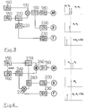
- the first embodiment of the modulation part will be discussed in more detail with reference to FIG. 3.
- a first oscillator 150 and a second oscillator 160 each provide a modulation frequency ⁇ 1 or ⁇ 2.
- the signals from the two oscillators 150 and 160 are fed to a mixer 170, which is designed, for example, as a diode mixer.
- the mixer 170 provides a sum and a difference signal ⁇ 1 + ⁇ 2 and ⁇ 1 - ⁇ 2. After suitable level adjustment and filtering, for example with the aid of a first amplifier 180, this signal is available as a modulation signal M.
- Part of the modulation signal is coupled out on the mixer output side via a second coupler 190 and provided as a one-tone detection signal S via a second amplifier 200.
- one of the two oscillators 150 or 160 couples out a signal part via a first coupler 210 and one via a frequency doubler 220 third amplifier 230 supplied.
- the two-tone detection signal T is then present at the output of the third amplifier 230.
- the one-tone and the two-tone method can thus be implemented simultaneously, ie a two-channel measuring arrangement can be set up. where a one-tone detection signal S or a two-tone detection signal T is available in the measuring and reference channel. In this way, a different operating mode can be set in each channel during the measurement operation, the mixed operation implemented in this way taking place simultaneously, ie simultaneously.
- the second embodiment described in FIG. 4 also starts from two oscillators 150 and 160, each of which supplies a modulation frequency ⁇ 1 and ⁇ 2. Both oscillators are provided with means which enable a common tuning or which are used for readjustment in the sense of a drift compensation.
- the two oscillators 150 and 160 are each led to a first coupler 240 and a second coupler 250.
- the two modulation frequencies ⁇ 1 and ⁇ 2 of the oscillators 150 and 160 also arrive at a combination member 260, which is designed, for example, as a resistance network or by means of a ring core coupling.
- the harmonic-free addition result of the two original frequencies ⁇ 1 and ⁇ 2 is obtained and provided as a modulation signal M via a first amplifier 180.
- the signal components obtained from the first and second couplers 240, 250 are fed to a mixer 270.
- a two-tone detection signal T is obtained on the mixer output side via a third amplifier 230.
- the one-tone detection signal S is obtained by coupling out with the aid of a third coupler 280, which is looped into the signal connection from the second coupler 250 to the mixer 270.
- the means mentioned for coupling the oscillators 150 and 160 can be implemented, for example, mechanically or electronically with the aid of a PLL control or using suitable software.
- a simultaneous two-channel method for evaluating a measurement signal according to magnitude and phase with respect to a reference signal is possible with the arrangement according to FIG. 4 if a suitable, adapted demodulation part is used.
- harmonic interference components in the modulation signal can be excluded from the outset, thereby reducing the selectivity, e.g. B. in the spectroscopic examination of trace gases with the aid of a modulated laser beam, which interacts with a sample, increased.
- a two-channel demodulation part with a one-tone and two-tone option is to be presented, with separate adjustability for the one-tone and two-tone method being given for each of the two channels CH1 and CH2 provided .
- FIG. 5 In the upper part of FIG. 5 is shown symbolically how a modulation signal M via a coupling element, for. B. a bias tea acts on a diode laser, the signal obtained interacting with a measuring section or a sample (symbolized by the arrow).
- Receivers are each provided in the measuring and reference channel, each of which delivers a detector signal D, which with the aid of amplifiers 290 and 300 is appropriately amplified and reaches an input of each channel 310, 320 of a phase-sensitive detector.
- Each channel 310 and 320 has an adjustable phase shifter 330 and a mixer 340.
- each channel has further amplifiers and / or filters 350 at least on the mixer input and output side.
- the signal obtained on the output side of the mixer 340 is then obtained via such an amplifier or filter 350 as a channel-specific measurement signal CH1, CH2.
- the phase shifters 330 of the respective channels can each be controlled with the one-tone signal or the two-tone signal, so that a simple switchover or selection of a predetermined method for each measurement and reference channel is possible.
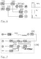
- FIGS. 6 and 7 a demodulation method based on narrow-band filtering of the measurement signal at a fixed intermediate frequency is to be explained in accordance with a further exemplary embodiment, FIG. 6 showing a modulation part expediently to be used for this purpose.
- the special modulation part has two oscillators 150 and 160, each providing a modulation frequency ⁇ 1 and ⁇ 2. Both modulation frequencies arrive at a mixer 360, which supplies the modulation signal M on the output side via a first amplifier 180. With a first coupler 370 and a second coupler 380, a part of the output signal from the oscillator 160 and one from the oscillator 150 is coupled out and obtained via a second and a third amplifier 200, 230 as signals 1 and 2 for phase-sensitive detection. So there are signals at the outputs 1 and 2, each with a different frequency and correlating with the frequencies ⁇ 1 and ⁇ 2 available.
- the signals M, 1 and 2 obtained from the modulation part according to FIG. 6 are used for modulation and for phase-sensitive detection, as explained.
- the demodulation part or the phase-sensitive detector 390 according to FIG. 7 is characterized in that with the signal 1 the detector signal is mixed to an intermediate frequency IF and filtered there in a narrow band.
- a first phase shifter 400 is provided which interacts with a first mixer 410, the first input of the first mixer 410 being connected to the output of the first phase shifter 400 and the second input of which receives the detector signal D via suitable amplifiers or filters 420, 290 .
- the output signal of the first mixer 410 passes through a further filter 430 to the first input of a second mixer 440, the second input of which is connected to a second phase shifter 450.
- the input of the second phase shifter 450 carries the signal 2.
- the signal at the output of the filter 430 is therefore mixed with the signal 2 a second time.
- the mixed signal is passed to an output amplifier 460, which carries the output signal of the channel CH1 under consideration. It is within the meaning of the invention that the phase-sensitive detector 390 or the single measuring channel CH1 shown in FIG. 7 is duplicated in order to form or maintain a further or more channels. It is also within the meaning of the invention that instead of the modulation part according to FIG.
- a modulation with the arrangements according to the exemplary embodiments according to FIGS. 3 and 4 can be carried out, in which case the signals 1 and 2 in each case either the one-tone detection signal S or the two-tone detection signal T corresponds.
- the particular advantage of the demodulation part according to FIG. 7 is that with the special type of narrow-band filtering of the measurement signal it is possible to better suppress any residual disturbing harmonics that may be present, for example when the modulation part according to FIG. 3 is implemented.
- the intermediate frequency filtering at a predetermined intermediate frequency of, for example, 10.7 MHz can achieve that commercial components, e.g. B. can be used from broadcast technology.
- a first and a second coupling element 470, 480 are used to determine whether the mixer input levels are in a predetermined range, i.e. whether the local oscillator LO is receiving a specified minimum level and whether the level at the RF input of mixer 340 is below the compression point.
- This check is expediently carried out by leading and monitoring the signals coupled out on the first and second couplers 470, 480 to a suitable level meter 490 or 500.
- the level measurement can be carried out, for example, with the aid of an HF millivolt meter.
- these values could be digitized and sent to a computer for deriving control variables for optimizing the operation of the method for evaluating the measurement signal according to amount and phase in relation to the reference signal.
- absorption-spectroscopic measuring sections can, for. B. for the analysis of trace gases can be constructed particularly inexpensively and easily adaptable to the special measuring task.
- a simultaneous, simultaneous measurement operation in several channels for. B. possible in the measurement and reference channel with different modulation techniques.
- the arrangement can be realized in a modular design and compatible with the connections to known embodiments, so that an easy, inexpensive retrofitting and modernization of existing systems is ensured.
- a signal received by a signal generator e.g. B. triggered a ramp for sampling the absorption of a measurement signal in a measuring cell.
- both the measurement signal and a reference or calibration signal are generated via the laser used, the measurement section and the detection system.
- the reference or calibration signal can be provided with the aid of a measuring cell with high absorption, which is penetrated by a small part of the laser light coupled out by the laser used. This ensures that there is a sufficiently high signal-to-noise ratio in the reference signal.
- a disturbance in the power supply of the laser used which is smaller than the ramp frequency for tuning the laser, causes a jitter or offset in the measurement signal.
- the change in the ramp frequency is indicated by the up and down arrows in the symbolic representation of the course of the ramp signal.
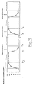
- the jitter mentioned is shown in a shift of the signal in the direction of the x-axis. This measurement signal jitter is shown in FIG. 12a for a series of measurement signals arriving on-line.
- the reference signal with a high signal-to-noise ratio is now used to generate a latch pulse L when a predetermined trigger threshold is exceeded
- the spectrum channel or scan assigned to this trigger pulse can be briefly stored.
- An on-line drift correction of the respective spectrum channel or the scan can now be carried out by moving the respective spectrum or the respective scan back into the actual central position. This precludes an undesired shift of the mean signal from occurring during subsequent averaging of the individual spectra.
- the spectra are advantageously digitized and stored in a buffer, so that the above-mentioned shift or backward shift can easily be carried out by an offset addition.
- the measurement signal arriving on-line first arrives at a first analog / digital converter 21, which on the output side has an exchangeable buffer arrangement 22; 23 communicates. Through the removable buffer arrangement 22; 23 dead time effects are avoided. That is, while e.g. B. stores the just digitized spectrum in the buffer 22, the last viewed spectrum in the buffer 23 is synchronous or asynchronous the averaged spectrum already stored in a memory 24 is added up.
- the buffers 22 and 23 are interactively connected on the output side via a first adder 25 to the memory 24 already mentioned.
- the determination of the shift of the on-line measurement signals to the reference or calibration signal is carried out as follows. After all existing memory cells and registers have been reset, a default register 26 with a selected channel, e.g. B. 64 preloaded. The channel is selected based on e.g. B. 128 spectral channels, the selected channel should be at least approximately in the middle of the total number of spectral channels.
- the reference signal is digitized via a second analog / digital converter 27, which can be combined with the first analog / digital converter 21.
- a latch pulse is then generated via a trigger 28 when the reference signal exceeds or falls below a predetermined central trigger level.
- An external start pulse causes an address counter 29 to start up from the system clock (clock) and the on-line measurement signal is digitized in parallel to the reference signal with the first analog / digital converter 21. The conversion result obtained in this way is transferred to the removable buffer arrangement 22; 23 written. The respective address is specified by the address counter 29.
- the latch pulse from trigger 28 occurs, the current buffer address is transferred to the first index register 21.0.
- there is initially no change since all addresses are preset with 0, ie only operations of the form 0 + 0 are carried out.
- the next cycle is then initiated again by an external start pulse. With this start pulse, the content of the first index register 21.0 is negated in the second index register 21.1, which now contains the negative trigger value from buffer 23.
- a second adder 21.2 the negative index value of the second register 21.1 is added to the value from the default register 26, as a result of which the offset caused by the jitter is obtained.
- the removable buffer arrangement 22; 23 switched so that the current data are now written into the buffer 22.
- the address counter 29 points to the current buffer address (CBA)
- the current memory address (CMA) is calculated from the addition of CBA and the offset for the averaging process in the memory 24.
- the resolution that can be achieved depends on the number of spectral channels. Given a predefined number of averages N, n + 1 cycles are to be run through due to the change buffer arrangement. With high averaging (N> 1000) the resulting dead time is negligible, so that the averaged signal is available in real time.
- a diode laser 32 is connected to a control unit 31 in such a way that the diode laser 32 can be tuned on the one hand and frequency modulation can additionally be used to increase the sensitivity of the measuring arrangement.
- the modulation of the diode laser 32 is advantageously implemented via a coupling element 311.
- the laser radiation from the diode laser 32 then reaches an absorption measuring cell 700, which is connected to a measuring detector 38 on the radiation output side.
- the output of the measurement detector 38 is led, possibly via an amplifier 312, to the input of a measurement signal processing device 3100.
- the measurement signal processing device 3100 is connected to the coupling-in element 311 in order to obtain a modulation reference signal.
- a device for determining a residual amplitude or residual amplitude values k 314 is connected to the coupler 313 and supplies the measurement signal processing device 3100 with a value which is proportional to the intensity I0 and any adjustment-dependent, absorption-independent intensity changes that are present.
- the device for determining the residual amplitude 14 can comprise, for example, a demodulator with a downstream level evaluation unit or a high-frequency voltmeter.
- the diode laser 32 shown in FIG. 14 is frequency modulated, the frequency f being 100 MHz, for example.
- This modulation produces an upper and a lower sideband with opposite phase positions at a modulation index of ⁇ ⁇ 1 at a distance from the modulation frequency from the carrier.
- the measuring detector 38 is of broadband design so that it can detect all resulting frequency mixed products and can derive corresponding signals including those at the modulation frequency. Since the upper and lower sidebands have an opposite phase position, there is also a phase shift of 180 ° for the output currents of the measuring detector 38 at the modulation frequency, so that the two signals differ after phase-sensitive detection, for example by means of the measuring signal processing device 3100, cancel to a net zero signal.
- the diode laser 32 is now tuned with an injection current over an absorption line of a trace substance or gas, the side band located within the absorption line is weakened in each case. This disrupts the balance described above and the result is a signal other than zero.
- frequency and amplitude modulation are coupled. If charge carriers are periodically injected into the pn junction of the diode laser using a modulation current, both the charge carrier density and the refractive index in the laser resonator change. This coupling of both types of modulation manifests itself in the so-called residual amplitude modulation. This should be as small as possible, but can never be completely suppressed.
- a particular advantage of the fourth aspect of the invention is that normalization based on the above-described determination of the original intensity I0 in addition to the fluctuations in the intensity of the diode laser 32 also the misalignment effects and drifts of the entire measuring arrangement, in particular the absorption measuring cell 700 and signs of aging of the measuring detector 38 considered.
- the procedure described above is independent of changes in the background radiation, so that the additional measures required to eliminate such effects or their effects can be omitted.
- the original intensity of a diode laser can thus be reliably detected with a single measurement detector and a normalization can be carried out on the basis of this variable.
- the standardization carried out in this way is free from any influence due to the background radiation and not only changes in the power of the diode laser, but also changes due to misalignment of the optics of the measurement setup are detected.
- 16 shows the representation of a switching cycle for alternating sample and background measurement according to the fifth aspect.
- the type and the concentration of trace or sample gas molecules which are located in a measuring cell are determined by evaluating absorption lines A in a predetermined wavelength-dependent measuring window MF.
- the electrical and / or magnetic field according to the invention is brought into effect on the trace or sample gas located in the measuring cell.
- This field effect changes the position of the absorption line A under consideration to the position of the absorption line A '.
- the measurement window MF under consideration is thus free of absorption lines which can be traced back to the trace or sample gas.
- Sensitivity-limiting subsurface structures e.g. B. the disturbing calibration structures generated by resonators and pressure-widened, time-varying atmospheric absorption lines, for. B. water, are not affected by the field effect. Now takes place during the field exposure a determination of the underground structures in a known manner. When the field activity cycle ends, the absorption line A 'is virtually transported back into the measuring window MF.
- a sample and background measurement can now be achieved at extremely short cyclical intervals by simply switching the external field on and off.
- the time period between sample and background measurement that is otherwise required for gas exchange can be omitted, as a result of which the influence of disruptive drifts within the entire measuring device is reduced.
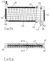
- the measuring cell is designed to act on an electrical field on the trace or sample gas, it is necessary to develop the Stark effect that the substances contained in the gas, which can be detected by absorption spectroscopy, have a permanent dipole moment.
- the measuring cell 41 in plan view, the measuring cell 41 having a gas inlet 42 and a gas outlet 43.
- the gas outlet 43 is connected to a pump, not shown.
- the measuring beam is suitably folded in the measuring cell 41.
- a multiple reflection cell is formed with a parallel beam or in the manner of a White or Herriott cell.
- a laser beam 47 is now coupled into the cell volume via a coupling path 48 and interacts with the trace or sample gas in the measuring cell 41 via the adjustment, x and y mirrors 46, 44, 45 with multiple reflection.
- the absorptions determined by the properties of the trace or sample gas are determined with a detector 49 arranged on the radiation output side.
- the electric field now acts perpendicular to the plane of the drawing on the trace or sample gas located in the measuring cell 41.
- the measuring cell has two capacitor plates 410 which at least partially enclose the measuring cell 41 essentially parallel to the formation of a plate capacitor.
- the distance between the capacitor plates 410 is essentially determined by the diameter of the laser beam 47, as symbolically shown in FIG. 17b.
- Switching means (not shown) cyclically connects the plate capacitor consisting of the capacitor plates 410 to a voltage source (not shown) for alternating sample and background measurement.
- a switchable electromagnet can surround the measuring cell 41 with the aim of influencing the trace or sample gas according to the Zeeman effect. Due to the electromagnet to be cyclically connected to a current source, the trace or sample gas is acted upon by an external, essentially homogeneous magnetic field, so that the shift shown in FIG. 16 or the masking of the relevant absorption line from the respective measuring window MF Determination of the underground structure results.
- the previously required physical exchange of the gas for determining the background structure can be omitted.
- an electrical or magnetic field to the measuring cell, the energy levels of gas molecules within the cell exposed to the field are shifted in a defined manner. Sensitivity-limiting background structures remain unaffected by the field, so that sample and background absorption can be separated in a simple manner.
Landscapes
- Physics & Mathematics (AREA)
- Spectroscopy & Molecular Physics (AREA)
- Analytical Chemistry (AREA)
- Health & Medical Sciences (AREA)
- Life Sciences & Earth Sciences (AREA)
- Chemical & Material Sciences (AREA)
- Optics & Photonics (AREA)
- Biochemistry (AREA)
- General Health & Medical Sciences (AREA)
- General Physics & Mathematics (AREA)
- Immunology (AREA)
- Pathology (AREA)
- Investigating Or Analysing Materials By Optical Means (AREA)
Applications Claiming Priority (10)
| Application Number | Priority Date | Filing Date | Title |
|---|---|---|---|
| DE4320037 | 1993-06-17 | ||
| DE4320038 | 1993-06-17 | ||
| DE4320036 | 1993-06-17 | ||
| DE19934320036 DE4320036C2 (de) | 1993-06-17 | 1993-06-17 | Verfahren und Anordnung zur Driftkorrektur zeitdiskreter Meßsignale bezogen auf ein Referenzsignal, insbesondere in der absorptionsspektroskopischen Spurengasanalytik |
| DE19934320038 DE4320038C1 (de) | 1993-06-17 | 1993-06-17 | Anordnung zum Bewerten eines Meßsignals nach Betrag und Phase in Bezug auf ein Referenzsignal |
| DE19934320037 DE4320037A1 (de) | 1993-06-17 | 1993-06-17 | Verfahren und Anordnung zur Stromversorgung eines Meßlasers, insbesondere eines Diodenlasers zur absorptionsspektroskopischen Spurengasanalytik |
| DE19934333422 DE4333422C1 (de) | 1993-09-30 | 1993-09-30 | Verfahren und Anordnung zur Bestimmung und Normierung der Intensität eines Meßsignals, insbesondere bei der Modulations-Laser-Absorptionsspektroskopie |
| DE4333422 | 1993-09-30 | ||
| DE19934338233 DE4338233C2 (de) | 1993-11-09 | 1993-11-09 | Verfahren und Anordnung zur abwechselnden Proben- und Untergrundmessung, insbesondere bei der hochempfindlichen absorptionsspektroskopischen, selektiven Spurengasanalyse |
| DE4338233 | 1993-11-09 |
Publications (2)
| Publication Number | Publication Date |
|---|---|
| EP0629851A2 true EP0629851A2 (fr) | 1994-12-21 |
| EP0629851A3 EP0629851A3 (fr) | 1995-03-22 |
Family
ID=27511683
Family Applications (1)
| Application Number | Title | Priority Date | Filing Date |
|---|---|---|---|
| EP94109051A Withdrawn EP0629851A3 (fr) | 1993-06-17 | 1994-06-13 | Dispositif pour analyse de traces de gaz par spectroscopie d'absorption. |
Country Status (1)
| Country | Link |
|---|---|
| EP (1) | EP0629851A3 (fr) |
Cited By (7)
| Publication number | Priority date | Publication date | Assignee | Title |
|---|---|---|---|---|
| WO2003091670A1 (fr) * | 2002-04-23 | 2003-11-06 | Forschungszentrum Karlsruhe Gmbh | Utilisation de traceurs et procede faisant appel a des traceurs |
| WO2005088275A1 (fr) * | 2004-03-09 | 2005-09-22 | Senscient Limited | Detection de gaz |
| CN104596938A (zh) * | 2014-12-31 | 2015-05-06 | 聚光科技(杭州)股份有限公司 | 气体传感器及检测方法 |
| US20200163314A1 (en) * | 2017-07-23 | 2020-05-28 | Terahertz Group Ltd. | System and method for non-invasively determining egg properties |
| CN114518180A (zh) * | 2022-01-21 | 2022-05-20 | 北京航空航天大学 | 一种基于激光色散光谱的温度和振幅遥测系统与方法 |
| CN118549383A (zh) * | 2024-07-26 | 2024-08-27 | 南昌航空大学 | 一种基于外差相敏色散的痕迹气体浓度检测装置 |
| CN119935954A (zh) * | 2025-01-23 | 2025-05-06 | 安徽大学 | 基于v型波长调谐和调制技术的气体检测装置和方法 |
Family Cites Families (6)
| Publication number | Priority date | Publication date | Assignee | Title |
|---|---|---|---|---|
| JPS61202128A (ja) * | 1985-03-06 | 1986-09-06 | Hitachi Ltd | 半導体レ−ザヘテロダイン干渉計 |
| DE3510052A1 (de) * | 1985-03-20 | 1986-09-25 | Kernforschungszentrum Karlsruhe Gmbh, 7500 Karlsruhe | Verfahren und prozessphotometer zur kontinuierlichen messung von konzentrationen |
| US4884286A (en) * | 1985-12-12 | 1989-11-28 | Texas Instruments Inc. | Elastic buffer for local area networks |
| US4765736A (en) * | 1986-07-24 | 1988-08-23 | Electric Power Research Institute | Frequency modulation spectroscopy using dual frequency modulation and detection |
| DE3809213A1 (de) * | 1988-03-18 | 1989-10-05 | Bodenseewerk Perkin Elmer Co | Atomabsorptions-spektrometer |
| US5103453A (en) * | 1991-02-12 | 1992-04-07 | Aerodyne Research, Inc. | Method and means for controlling the frequency and power output of a tunable diode laser |
-
1994
- 1994-06-13 EP EP94109051A patent/EP0629851A3/fr not_active Withdrawn
Cited By (11)
| Publication number | Priority date | Publication date | Assignee | Title |
|---|---|---|---|---|
| WO2003091670A1 (fr) * | 2002-04-23 | 2003-11-06 | Forschungszentrum Karlsruhe Gmbh | Utilisation de traceurs et procede faisant appel a des traceurs |
| WO2005088275A1 (fr) * | 2004-03-09 | 2005-09-22 | Senscient Limited | Detection de gaz |
| US7705988B2 (en) | 2004-03-09 | 2010-04-27 | Senscient Limited | Gas detection |
| CN104596938A (zh) * | 2014-12-31 | 2015-05-06 | 聚光科技(杭州)股份有限公司 | 气体传感器及检测方法 |
| CN104596938B (zh) * | 2014-12-31 | 2017-08-11 | 聚光科技(杭州)股份有限公司 | 气体传感器及检测方法 |
| US20200163314A1 (en) * | 2017-07-23 | 2020-05-28 | Terahertz Group Ltd. | System and method for non-invasively determining egg properties |
| US12082561B2 (en) * | 2017-07-23 | 2024-09-10 | Terahertz Group Ltd. | System and method for non-invasively determining egg properties |
| CN114518180A (zh) * | 2022-01-21 | 2022-05-20 | 北京航空航天大学 | 一种基于激光色散光谱的温度和振幅遥测系统与方法 |
| CN114518180B (zh) * | 2022-01-21 | 2022-12-09 | 北京航空航天大学 | 一种基于激光色散光谱的温度和振幅遥测系统与方法 |
| CN118549383A (zh) * | 2024-07-26 | 2024-08-27 | 南昌航空大学 | 一种基于外差相敏色散的痕迹气体浓度检测装置 |
| CN119935954A (zh) * | 2025-01-23 | 2025-05-06 | 安徽大学 | 基于v型波长调谐和调制技术的气体检测装置和方法 |
Also Published As
| Publication number | Publication date |
|---|---|
| EP0629851A3 (fr) | 1995-03-22 |
Similar Documents
| Publication | Publication Date | Title |
|---|---|---|
| EP0263931B1 (fr) | Procédé et dispositif pour la mesure continue de la concentration d'un composant d'un gaz | |
| DE68924163T2 (de) | Verfahren und vorrichtung zur spektroskopischen messung der gaskonzentration. | |
| DE4437575C2 (de) | Spektrometer mit kohärenter und periodisch gepulster Strahlung | |
| EP0438465B1 (fr) | Procede et dispositif de detection quantitative de substances optiquement actives | |
| DE3643629A1 (de) | Verfahren zur stabilisierung der wellenlaenge eines halbleiterlasers und halbleiterlaser-wellenlaengenstabilisators | |
| DE102006058395B4 (de) | Anordnung zur elektrischen Ansteuerung und schnellen Modulation von THz-Sendern und THz-Messsystemen | |
| DE2438294A1 (de) | Verfahren zur messung kleiner gaskonzentrationen | |
| EP3798611B1 (fr) | Procédé et analyseur de gaz permettant de mesurer la concentration d'un composant gazeux dans un gaz mesuré | |
| EP0195179B1 (fr) | Photomètre pour la mesure continue de concentrations | |
| WO2018115472A1 (fr) | Procédé de correction de la longueur d'onde et de la gamme d'accord d'un spectromètre à laser | |
| DE60311182T2 (de) | Laserspektroskopie mittels einer Master-Slave-Steuerungsarchitektur | |
| DE3819531A1 (de) | Signalprozess- und betriebstechnik zur laserspektroskopischen mengenbestimmung von ammoniak in gasgemischen | |
| DE10044404C2 (de) | Verfahren und Vorrichtung zur Erzeugung von stabilisierten ultrakurzen Laser-Lichtpulsen | |
| DE102020115338B3 (de) | Optische Abtastung | |
| EP0370033B1 (fr) | Procede et dispositif d'analyse par micro-ondes | |
| EP0629851A2 (fr) | Dispositif pour analyse de traces de gaz par spectroscopie d'absorption | |
| DE10238356A1 (de) | Quantitative spektroskopische Bestimmung eines Absorbers | |
| WO2015039936A1 (fr) | Procédé et analyseur de gaz permettant de mesurer la concentration d'un composant gazeux dans un gaz de mesure | |
| EP2455733A1 (fr) | Procédé et agencement de mesure pour la spectroscopie à modulation de longueurs d'onde | |
| EP1063518B1 (fr) | Appareil pour analyser un échantillon gazeux par l'absorption d'infrarouge | |
| AT525942B1 (de) | Verfahren und Vorrichtung zur VCD-Analyse eines Analyten | |
| DE68907524T2 (de) | Elektrische Signalüberwachungsvorrichtung. | |
| EP3417299B1 (fr) | Analyseur de spectre et procédé d'analyse spectrale | |
| DE4320038C1 (de) | Anordnung zum Bewerten eines Meßsignals nach Betrag und Phase in Bezug auf ein Referenzsignal | |
| DE102021209443A1 (de) | Terahertzwellen-Dämpfung-Totalreflexions-Spektroskopieverfahren, Terahertzwellen-Dämpfung-Totalreflexions-Spektroskopievorrichtung und Druckanwendungsvorrichtung |
Legal Events
| Date | Code | Title | Description |
|---|---|---|---|
| PUAI | Public reference made under article 153(3) epc to a published international application that has entered the european phase |
Free format text: ORIGINAL CODE: 0009012 |
|
| AK | Designated contracting states |
Kind code of ref document: A2 Designated state(s): DE FR GB IT |
|
| PUAL | Search report despatched |
Free format text: ORIGINAL CODE: 0009013 |
|
| AK | Designated contracting states |
Kind code of ref document: A3 Designated state(s): DE FR GB IT |
|
| 17P | Request for examination filed |
Effective date: 19950406 |
|
| STAA | Information on the status of an ep patent application or granted ep patent |
Free format text: STATUS: THE APPLICATION HAS BEEN WITHDRAWN |
|
| 18W | Application withdrawn |
Withdrawal date: 19960916 |