EP0370096B1 - Finisseur a tunnel - Google Patents
Finisseur a tunnel Download PDFInfo
- Publication number
- EP0370096B1 EP0370096B1 EP89906077A EP89906077A EP0370096B1 EP 0370096 B1 EP0370096 B1 EP 0370096B1 EP 89906077 A EP89906077 A EP 89906077A EP 89906077 A EP89906077 A EP 89906077A EP 0370096 B1 EP0370096 B1 EP 0370096B1
- Authority
- EP
- European Patent Office
- Prior art keywords
- air
- steam
- rollers
- tunnel finisher
- supply
- Prior art date
- Legal status (The legal status is an assumption and is not a legal conclusion. Google has not performed a legal analysis and makes no representation as to the accuracy of the status listed.)
- Expired - Lifetime
Links
- 230000004888 barrier function Effects 0.000 claims description 2
- 238000010438 heat treatment Methods 0.000 claims description 2
- 238000010409 ironing Methods 0.000 description 4
- 230000008901 benefit Effects 0.000 description 3
- 238000011161 development Methods 0.000 description 1
- 230000018109 developmental process Effects 0.000 description 1
- 230000008030 elimination Effects 0.000 description 1
- 238000003379 elimination reaction Methods 0.000 description 1
- 238000000605 extraction Methods 0.000 description 1
- 238000007730 finishing process Methods 0.000 description 1
- 238000000034 method Methods 0.000 description 1
- 238000005192 partition Methods 0.000 description 1
- 238000000926 separation method Methods 0.000 description 1
Images


Classifications
-
- D—TEXTILES; PAPER
- D06—TREATMENT OF TEXTILES OR THE LIKE; LAUNDERING; FLEXIBLE MATERIALS NOT OTHERWISE PROVIDED FOR
- D06B—TREATING TEXTILE MATERIALS USING LIQUIDS, GASES OR VAPOURS
- D06B23/00—Component parts, details, or accessories of apparatus or machines, specially adapted for the treating of textile materials, not restricted to a particular kind of apparatus, provided for in groups D06B1/00 - D06B21/00
- D06B23/14—Containers, e.g. vats
- D06B23/16—Containers, e.g. vats with means for introducing or removing textile materials without modifying container pressure
-
- D—TEXTILES; PAPER
- D06—TREATMENT OF TEXTILES OR THE LIKE; LAUNDERING; FLEXIBLE MATERIALS NOT OTHERWISE PROVIDED FOR
- D06F—LAUNDERING, DRYING, IRONING, PRESSING OR FOLDING TEXTILE ARTICLES
- D06F73/00—Apparatus for smoothing or removing creases from garments or other textile articles by formers, cores, stretchers, or internal frames, with the application of heat or steam
- D06F73/02—Apparatus for smoothing or removing creases from garments or other textile articles by formers, cores, stretchers, or internal frames, with the application of heat or steam having one or more treatment chambers
Definitions
- the invention relates to a tunnel finisher according to the preamble of claim 1.
- Such a tunnel finisher is known from DE-PS 35 19 568. This comprises a steam chamber and a finish chamber separated from it by air rollers. An exhaust air chamber leads away from the ceiling of the steam chamber.
- the object of the invention is to provide a tunnel finisher of the type described at the outset, which is of particularly compact design and in which the steam consumption is low.
- the air flow 9 thus virtually forms a partition and prevents the steam from entering the chamber 9.
- the steam is then concentrated, to a large extent, excreted through the chamber 13 in the first circulating air cycle.
- the steam which naturally aspires upwards, is supported by the suction against the direction of the air flow 9 and leads to swirling and additionally suck in air from the chamber 9 as a parallel cross section.
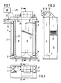
- the tunnel finisher has a housing 1 with an inlet 2 and an outlet 3.
- the entrance 2 is closed by an inlet-side pair of air rollers 4, 5 and the outlet by an outlet-side pair of air rollers 6, 7 in such a way that a piece of clothing to be treated can be passed through, but the interior of the chamber is sealed against the escape of steam to the outside remains.
- the interior of the chamber consists of a first section on the inlet side, the steam chamber 8, and an adjoining section outlet-side section, the circulating air chamber 9.
- a steam nozzle arrangement 10 which extends over the entire height of the chamber and via which steam can be introduced into the interior of the steam chamber.
- the circulating air space 9 opens on its underside into a return duct 11, which leads to the suction side of a circulating device 12.
- the circulating device 12 which is driven by a drive motor 16, is connected on the exhaust side to the upper side of the circulating space 9.
- a control flap 14 leading to an outlet opening 13 is provided, which can be moved between a closed and an open position via a lifting magnet 15 and a linkage connected to the flap.
- a heater 17 is provided, through which the air to be returned flows and which opposes the air with a certain resistance, so that a certain dynamic pressure arises at the bottom entrance of the return duct 11.
- the air rollers 4 to 7 have inlet openings 18, 19 on the bottom.
- An air supply duct 20, 21 is provided directly below each air roller.
- the air supply channels are connected via openings 22, 23 to the steam space 8 or the air circulation space on the inlet side.
- openings 24 are located directly below the openings 18, 19 of the air rollers running above them. In this way, air is led from the interior of the chamber into the air rollers.
- a conveyor with a rotating chain 25 with hanging grippers 26 is provided, which rotates so that the ironing material to be processed dips on the input side between the rollers 4, 5 and dips on the output side between the rollers 6, 7.
- a proximity switch or limit switch 27 is provided on the input side, which responds to that the ironing material to be processed has just been brought into the position shown in FIG. 1 by the gripper, in which the material is immersed between the two air rollers 4, 5 on the input side.
- a controller 28 is provided. On the input side, this is connected to limit switch 27. On the output side, the control is connected to the solenoid 15 for setting the open position of the control flap 14 or for switching the steam supply 10 on or off.
- the underside of the air rollers can have two disks 29, 30 arranged coaxially to one another and rotatable relative to one another with congruent bores 31, 32.
- the cross-section of the remaining openings can be adjusted by turning the discs against each other.
- the cross section of the air supply channels 18, 19 or also the inlet opening 24 for the passage of air is preferably smaller for the outlet-side air rollers 6, 7 than for the inlet-side air rollers 4, 5.
- the distance between two successive grippers 26, 33 is selected such that a second item of clothing 34, indicated by a bracket in FIG. 1, enters between the air rollers on the input side when the first item of clothing 35, also indicated by a clip, plunges between the pair of air rollers on the output side.
- a signal is fed to the control 28 via the limit switch 27 as soon as the second item of clothing 34 dips between the pair of air rollers on the input side.
- the steam supply is blown into the steam space 8 via the steam nozzle arrangement.
- the steam nozzles remain open, time-controlled, until the garment has the steam nozzles has happened and so that the material is sufficiently relaxed for the ironing process.
- the garment then enters the air circulation space 9. Here it is tumbled or ironed and dried by the heated circulating air flow before it emerges between the pair of air rollers 6, 7.
- the control 28 causes the control flap 14 to be brought into the open position via the lifting magnet 15 in such a way that up to about 20% of the circulating air through the. Opening 13 is guided to the outside.
- the internal air is removed in approximately the same ratio as the supply of the steam via the steam nozzle arrangement 10.
- the steam that is not condensed in the item of clothing is thus eliminated from the circulating air.
- the control circuit is designed so that after switching off the steam supply, the control flap 14 is only closed with a time delay so that the residual steam can largely escape from the chamber.
- the control flap is closed again and the complete air flow causes the ironing effect.
- the air flow emerging from the recirculation space 9 into the return duct 11 is somewhat slowed down by the air resistance of the heating, and a certain dynamic pressure arises at the bottom end of the duct 11, which leads to air entering the air rollers via the ducts 20, 21.
- the control flap 14 is opened when the second item of clothing is immersed between the air rollers on the input side and thus the first item of clothing is immersed between the air rollers on the output side.
- air is removed and thus the internal pressure and thus also the dynamic pressure are reduced.
- the internal pressure in the air rollers drops, so that the item of clothing that has already been treated is no longer deformed when it passes through the air rollers on the outlet side. Since the air duct cross-section for the air rollers on the inlet side is larger than for the air rollers on the outlet side, these are subjected to more air in the interior and therefore close more than the air roller on the outlet side.
- a detector 36 in the form of a light barrier is provided in front of the steam nozzle arrangement 10 instead of the limit switch 27 in the direction of travel.
- the light source is arranged on one side of the channel and a light detector 37 is arranged on the opposite side of the channel.
- the detector is located just a few millimeters in front of the steam nozzles. It is connected on the output side to the controller 28.
- the controller 28 is designed so that the steam supply is switched on as long as the detector detects the passage of a material to be treated. In this way it is achieved that, regardless of the operating speed and regardless of the width of the material to be treated, the steam supply is switched on only while a material to be treated is passing by and thus only the minimum amount of steam required is supplied.
- the tunnel finisher is the same as the first embodiment. Since the steam suction takes place spatially in the area directly behind the steam nozzles and the steam is partly discharged via the outlet opening 13, the emerging garment in the rear part of the tunnel is no longer subjected to steam. This enables a continuous finishing process.
Landscapes
- Engineering & Computer Science (AREA)
- Textile Engineering (AREA)
- Treatment Of Fiber Materials (AREA)
- Accessory Of Washing/Drying Machine, Commercial Washing/Drying Machine, Other Washing/Drying Machine (AREA)
Abstract
Claims (14)
- Finisseur à tunnel comprenant une entrée (2) et une sortie (3) et des paires de rouleaux (4, 5, 6, 7) disposées respectivement à l'entrée et à la sortie, un dispositif de transport avec des organes de préhension (26, 33) pour le passage de vêtements à traiter (34, 35) à travers un espace à vapeur (8) et un espace de circulation d'air (9) du finisseur à tunnel, un dispositif d'arrivée de vapeur (10) monté du côté intérieur de la paire de rouleaux à air (4, 5) située du côté de l'entrée à proximité de celle-ci, un dispositif de circulation (12) de l'atmosphère, et un canal (11) menant à une sortie d'air, caractérisé en ce que l'espace à vapeur (8) et l'espace de circulation d'air (9) sont directement juxtaposés et l'entrée du canal (11) menant à la sortie d'air est prévue dans la zone inférieure commune à l'espace à vapeur (8) et à l'espace de circulation d'air (9).
- Finisseur à tunnel selon la revendication 1, caractérisé en ce qu'il est prévu un détecteur destiné à indiquer le franchissement du dispositif d'arrivée de vapeur par un vêtement à traiter, une sortie d'air de section modifiable sur le dispositif de circulation et une commande reliée au détecteur et à la sortie d'air pour commander l'arrivée de la vapeur et régler la section de la sortie d'air, la commande étant conçue de telle sorte que pendant l'arrivée d'air, la section soit réglée de façon qu'une partie de la vapeur aspirée par l'installation de circulation soit évacuée vers l'extérieur.
- Finisseur à tunnel comprenant une entrée (2) et une sortie (3) et des paires de rouleaux (4, 5, 6, 7) disposées respectivement à l'entrée et à la sortie, un dispositif de transport avec des organes de préhension (26, 33) pour le passage de vêtements à traiter (34, 35) à travers un espace à vapeur (8) et un espace de circulation d'air (9) du finisseur à tunnel, un dispositif d'arrivée de vapeur (10) monté du côté intérieur de la paire de rouleaux à air (4, 5) située du côté de l'entrée à proximité de celle-ci, un dispositif de circulation (12) de l'atmosphère et un canal (11) menant à une sortie d'air, caractérisé en ce que l'espace à vapeur (8) et l'espace de circulation d'air (9) sont directement juxtaposés et en ce qu'il est prévu un détecteur (27, 36) pour indiquer le franchissement de l'installation d'arrivée de vapeur (10) par un vêtement à traiter (34), une sortie d'air de section modifiable sur le dispositif de circulation et une commande (28) reliée au détecteur (27, 36) et à la sortie d'air pour l'actionnement de l'arrivée de vapeur et le réglage de la section de la sortie d'air, la commande (28) étant conçue de telle sorte que pendant l'arrivée d'air, la section soit réglée de façon qu'une partie de la vapeur aspirée par le dispositif de circulation soit évacuée vers l'extérieur.
- Finisseur à tunnel selon la revendication 2, caractérisé en ce que la commande est conçue de telle sorte que la sortie d'air soit fermée lorsque l'arrivée de vapeur est arrêtée.
- Finisseur à tunnel selon l'une ou l'ensemble des revendications 2 à 4, caractérisé en ce qu'il est prévu une commande qui réduit l'arrivée d'air à l'intérieur de la paire de rouleaux à air (6, 7) située du côté de la sortie pendant le passage d'un premier vêtement (35) entre ceux-ci.
- Finisseur à tunnel selon l'une ou l'ensemble des revendications 1 à 5, caractérisé en ce que la distance entre deux organes de préhension (26, 33) est choisie de telle sorte qu'un second vêtement (34) entre du côté de l'entrée lorsque le premier vêtement (35) pénètre entre la paire de rouleaux à air (6, 7) située du côté de la sortie.
- Finisseur à tunnel selon l'une ou l'ensemble des revendications 3 à 6, caractérisé en ce que la commande est conçue de telle sorte que lors de l'entrée d'un vêtement (34), l'arrivée de vapeur soit mise en service et la sortie d'air ouverte.
- Finisseur à tunnel selon l'une ou l'ensemble des revendications 3 à 7, caractérisé en ce que la commande est conçue de telle sorte que l'arrivée de vapeur ne reste en service que tant que le détecteur perçoit la présence d'un vêtement devant l'installation d'arrivée de vapeur.
- Finisseur à tunnel selon la revendication 8, caractérisé en ce que le détecteur est disposé immédiatement avant l'installation d'arrivée de vapeur dans le sens de la marche.
- Finisseur à tunnel selon la revendication 8 ou 9, caractérisé en ce que le détecteur est constitué par un barrage photo-électrique.
- Finisseur à tunnel selon l'une ou l'ensemble des revendications 3 à 10, caractérisé en ce que la commande est conçue de telle sorte que la sortie d'air reste encore ouverte pendant une courte durée après l'arrêt de l'arrivée de vapeur.
- Finisseur à tunnel selon l'une ou l'ensemble des revendications 1 à 11, caractérisé en ce qu'un dispositif de chauffage (17) est prévu dans le canal de retour (11) reliant l'intérieur de la chambre au dispositif de circulation.
- Finisseur à tunnel selon l'une ou l'ensemble des revendications 1 à 12, caractérisé en ce que des canaux d'arrivée d'air (20, 21) assurant la liaison avec l'intérieur de la chambre sont prévus en-dessous des rouleaux à air (4, 5, 6, 7).
- Finisseur à tunnel selon l'une ou l'ensemble des revendications 1 à 13, caractérisé en ce que la section des canaux d'arrivée d'air (20) ou des ouvertures d'entrée (18, 19) dans les rouleaux à air (6, 7) situés du côté de la sortie est plus petite que pour les canaux (21) ou les rouleaux à air (4, 5) situés du côté de l'entrée.
Applications Claiming Priority (4)
| Application Number | Priority Date | Filing Date | Title |
|---|---|---|---|
| DE3818387 | 1988-05-30 | ||
| DE19883818387 DE3818387C2 (de) | 1988-05-30 | 1988-05-30 | Tunnelfinisher |
| DE8903655U DE8903655U1 (de) | 1988-05-30 | 1989-03-22 | Tunnelfinisher |
| DE8903655U | 1989-03-22 |
Publications (2)
| Publication Number | Publication Date |
|---|---|
| EP0370096A1 EP0370096A1 (fr) | 1990-05-30 |
| EP0370096B1 true EP0370096B1 (fr) | 1993-09-08 |
Family
ID=25868606
Family Applications (1)
| Application Number | Title | Priority Date | Filing Date |
|---|---|---|---|
| EP89906077A Expired - Lifetime EP0370096B1 (fr) | 1988-05-30 | 1989-05-30 | Finisseur a tunnel |
Country Status (7)
| Country | Link |
|---|---|
| US (1) | US5018371A (fr) |
| EP (1) | EP0370096B1 (fr) |
| JP (1) | JP2714566B2 (fr) |
| KR (1) | KR900702119A (fr) |
| DE (2) | DE8903655U1 (fr) |
| RU (1) | RU1834936C (fr) |
| WO (2) | WO1989012133A1 (fr) |
Families Citing this family (12)
| Publication number | Priority date | Publication date | Assignee | Title |
|---|---|---|---|---|
| US5376144A (en) * | 1991-01-23 | 1994-12-27 | American Laundry Machinery, Inc. | Process for treating cellulosic fiber-containing fabric |
| DE9311137U1 (de) * | 1993-07-26 | 1993-10-28 | Veit Gmbh & Co, 86899 Landsberg | Vorrichtung zur Dampfbehandlung und Heißluftbehandlung von Kleidungsstücken |
| US6311526B1 (en) * | 1999-08-11 | 2001-11-06 | Leonard Automatics, Inc. | Modular U-turn tunnel finisher |
| US6862774B2 (en) * | 2001-07-18 | 2005-03-08 | Leonard Automactics, Inc. | Continuous lint filtration system for a garment finishing machine |
| US6835258B2 (en) * | 2002-12-27 | 2004-12-28 | Sara Lee Corporation | Automated processes for the production of garments |
| US20050086826A1 (en) * | 2003-06-04 | 2005-04-28 | Frushtick Jeffrey N. | Tunnel finisher with infrared feedback temperature control |
| US7845197B2 (en) * | 2005-05-31 | 2010-12-07 | Leonard Automatics, Inc. | Triple pass tunnel finisher with an articulated spraying function |
| US7845037B2 (en) * | 2005-05-31 | 2010-12-07 | Leonard Automatics, Inc. | Triple pass tunnel finisher |
| DE602007006285D1 (de) | 2007-05-24 | 2010-06-17 | Rotondi Group S R L | Vorrichtung zur Behandlung von Kleidungsstücken, insbesondere zum Bedampfen und Belüften |
| EP3176310B1 (fr) * | 2007-08-03 | 2020-10-14 | Lg Electronics Inc. | Appareil de traitement de vêtements |
| EP2397603A1 (fr) * | 2010-06-17 | 2011-12-21 | Heike Brüske | Dispositif de nettoyage et de lissage de petites pièces de vêtement |
| USD1107359S1 (en) * | 2023-03-03 | 2025-12-23 | Gleener Inc. | Fabric care device |
Family Cites Families (11)
| Publication number | Priority date | Publication date | Assignee | Title |
|---|---|---|---|---|
| US2911729A (en) * | 1956-11-30 | 1959-11-10 | Byron A Wood | Method of and means for steam treating and vibrating garments |
| US3644085A (en) * | 1970-06-29 | 1972-02-22 | Mc Graw Edison Co | Garment finisher and method of finishing garments |
| US3765580A (en) * | 1972-02-14 | 1973-10-16 | Automatic Steam Products Corp | Garment dewrinkling process and apparatus |
| GB1401503A (en) * | 1972-11-01 | 1975-07-16 | Baker Perkins Jaxons Ltd | Machine for finishing washed or dry cleaned garments |
| DE3119618A1 (de) * | 1981-05-16 | 1983-01-05 | Herbert Kannegiesser Gmbh + Co, 4973 Vlotho | Vorrichtung zum glaetten von kleidungsstuecken |
| DE3119664C2 (de) * | 1981-05-16 | 1985-08-01 | Herbert Kannegiesser Gmbh + Co, 4973 Vlotho | Vorrichtung zum Glätten von Kleidungsstücken |
| DE3119560C2 (de) * | 1981-05-16 | 1984-05-10 | Herbert Kannegiesser Gmbh + Co, 4973 Vlotho | Vorrichtung zum Glätten von Kleidungsstücken |
| DE3519567C1 (de) * | 1985-05-31 | 1986-09-18 | Dipl.-Ing. Riba Gmbh & Co Kg, 5450 Neuwied | Tunnelfinisher |
| DE3519568C1 (de) * | 1985-05-31 | 1986-10-02 | Dipl.-Ing. Riba Gmbh & Co Kg, 5450 Neuwied | Tunnelfinisher |
| DE3710674A1 (de) * | 1987-03-31 | 1988-10-20 | Veit Gmbh & Co | Tunnelfinisher |
| DE3720581C1 (de) * | 1987-06-22 | 1988-08-18 | Guenther Dipl-Ing Riba | Tunnelfinisher mit Luftwalzen |
-
1989
- 1989-03-22 DE DE8903655U patent/DE8903655U1/de not_active Expired
- 1989-05-30 WO PCT/EP1989/000602 patent/WO1989012133A1/fr not_active Ceased
- 1989-05-30 JP JP1505516A patent/JP2714566B2/ja not_active Expired - Lifetime
- 1989-05-30 WO PCT/EP1989/000603 patent/WO1989012134A1/fr not_active Ceased
- 1989-05-30 US US07/458,680 patent/US5018371A/en not_active Expired - Fee Related
- 1989-05-30 KR KR1019900700181A patent/KR900702119A/ko not_active Abandoned
- 1989-05-30 DE DE89906077T patent/DE58905530D1/de not_active Expired - Fee Related
- 1989-05-30 EP EP89906077A patent/EP0370096B1/fr not_active Expired - Lifetime
-
1990
- 1990-01-29 RU SU904743154A patent/RU1834936C/ru active
Also Published As
| Publication number | Publication date |
|---|---|
| JPH02504482A (ja) | 1990-12-20 |
| RU1834936C (ru) | 1993-08-15 |
| WO1989012133A1 (fr) | 1989-12-14 |
| DE58905530D1 (de) | 1993-10-14 |
| EP0370096A1 (fr) | 1990-05-30 |
| WO1989012134A1 (fr) | 1989-12-14 |
| KR900702119A (ko) | 1990-12-05 |
| DE8903655U1 (de) | 1989-09-28 |
| JP2714566B2 (ja) | 1998-02-16 |
| US5018371A (en) | 1991-05-28 |
Similar Documents
| Publication | Publication Date | Title |
|---|---|---|
| DE2100116A1 (de) | Verfahren und Vorrichtung zum Aufformen, Aufdunsten, Ausrüsten od dergl von Kleidungsstücken | |
| WO1989012134A1 (fr) | Finisseur a tunnel | |
| EP0636734A1 (fr) | Appareil de traitement de vêtements au moyen de vapeur et d'air chaud | |
| EP1180231B1 (fr) | Sechoir pour materiau en bande ou en plaque | |
| EP0573726B1 (fr) | Tunnel de finition pour le traitement des vêtements | |
| EP0427122B1 (fr) | Dispositif de séchage des feuilles, respectivement des pièces détachées planes | |
| EP0319681B1 (fr) | Dispositif pour le traitement thermique d'une large bande de textile en déplacement continu | |
| DE19807511A1 (de) | Trocken- und/oder Fixiervorrichtung | |
| EP1889969B1 (fr) | Procédé destiné à défroisser des pièces de vêtements et finisseur à tunnel | |
| DE69215392T2 (de) | Vorrichtung zur kontinuierlichen Behandlung eines sich bewegenden Materials unbegrenzter Länge | |
| DE2915443A1 (de) | Verfahren und vorrichtung zum glaetten von kleidungsstuecken | |
| CH660286A5 (de) | Anlage und deren verwendung zum trocknen von tabakteilchen. | |
| DE3818387C2 (de) | Tunnelfinisher | |
| DE10162953A1 (de) | Vorrichtung zur Wärmebehandlung von Substanzen, insbesondere Nahrungsmitteln | |
| DE3119560A1 (de) | Vorrichtung zum glaetten von kleidungsstuecken | |
| DE3119664C2 (de) | Vorrichtung zum Glätten von Kleidungsstücken | |
| DE1635123A1 (de) | Vorrichtung zum Behandeln,vorzugsweise Daempfen und Farbstoffixieren,insbesondere von Textilgut | |
| DE4135909C2 (de) | Verfahren und Vorrichtung zum Mangeln textilen Gutes, insbesondere von Wäsche | |
| DE19537057C2 (de) | Trockenschrank zum Trocknen von textilen Kleidungsstücken | |
| EP0666354A2 (fr) | Dispositif pour le rétrécissement de bandes textiles | |
| EP0465950B1 (fr) | Séchoir à tapis par contact | |
| DE102009020885B4 (de) | Tunnel-Finisher und Verfahren zum Behandeln von Textilien | |
| EP0570970A1 (fr) | Séchoir de matières en vrac ou coulantes | |
| DE1410889A1 (de) | Verfahren und Vorrichtung zum Behandeln von Textilgut mittels Dampf | |
| CH654358A5 (de) | Einrichtung zum glaetten und trocknen feuchter waesche. |
Legal Events
| Date | Code | Title | Description |
|---|---|---|---|
| PUAI | Public reference made under article 153(3) epc to a published international application that has entered the european phase |
Free format text: ORIGINAL CODE: 0009012 |
|
| AK | Designated contracting states |
Kind code of ref document: A1 Designated state(s): AT BE CH DE FR GB IT LI LU NL SE |
|
| 17P | Request for examination filed |
Effective date: 19900130 |
|
| RBV | Designated contracting states (corrected) |
Designated state(s): DE FR GB IT |
|
| 17Q | First examination report despatched |
Effective date: 19920116 |
|
| RAP1 | Party data changed (applicant data changed or rights of an application transferred) |
Owner name: RIBA GEB. HILDEBRAND, JUTTA |
|
| RIN1 | Information on inventor provided before grant (corrected) |
Inventor name: RIBA, GUENTER |
|
| GRAA | (expected) grant |
Free format text: ORIGINAL CODE: 0009210 |
|
| AK | Designated contracting states |
Kind code of ref document: B1 Designated state(s): DE FR GB IT |
|
| REF | Corresponds to: |
Ref document number: 58905530 Country of ref document: DE Date of ref document: 19931014 |
|
| GBT | Gb: translation of ep patent filed (gb section 77(6)(a)/1977) |
Effective date: 19930924 |
|
| ET | Fr: translation filed | ||
| ITF | It: translation for a ep patent filed | ||
| PLBE | No opposition filed within time limit |
Free format text: ORIGINAL CODE: 0009261 |
|
| STAA | Information on the status of an ep patent application or granted ep patent |
Free format text: STATUS: NO OPPOSITION FILED WITHIN TIME LIMIT |
|
| 26N | No opposition filed | ||
| PGFP | Annual fee paid to national office [announced via postgrant information from national office to epo] |
Ref country code: FR Payment date: 19970516 Year of fee payment: 9 |
|
| REG | Reference to a national code |
Ref country code: GB Ref legal event code: 732E |
|
| REG | Reference to a national code |
Ref country code: FR Ref legal event code: TP |
|
| PG25 | Lapsed in a contracting state [announced via postgrant information from national office to epo] |
Ref country code: FR Free format text: LAPSE BECAUSE OF NON-PAYMENT OF DUE FEES Effective date: 19980531 |
|
| REG | Reference to a national code |
Ref country code: FR Ref legal event code: ST |
|
| PGFP | Annual fee paid to national office [announced via postgrant information from national office to epo] |
Ref country code: GB Payment date: 19990419 Year of fee payment: 11 |
|
| PGFP | Annual fee paid to national office [announced via postgrant information from national office to epo] |
Ref country code: DE Payment date: 19990629 Year of fee payment: 11 |
|
| PG25 | Lapsed in a contracting state [announced via postgrant information from national office to epo] |
Ref country code: GB Free format text: LAPSE BECAUSE OF NON-PAYMENT OF DUE FEES Effective date: 20000530 |
|
| GBPC | Gb: european patent ceased through non-payment of renewal fee |
Effective date: 20000530 |
|
| PG25 | Lapsed in a contracting state [announced via postgrant information from national office to epo] |
Ref country code: DE Free format text: LAPSE BECAUSE OF NON-PAYMENT OF DUE FEES Effective date: 20010301 |
|
| PG25 | Lapsed in a contracting state [announced via postgrant information from national office to epo] |
Ref country code: IT Free format text: LAPSE BECAUSE OF NON-PAYMENT OF DUE FEES;WARNING: LAPSES OF ITALIAN PATENTS WITH EFFECTIVE DATE BEFORE 2007 MAY HAVE OCCURRED AT ANY TIME BEFORE 2007. THE CORRECT EFFECTIVE DATE MAY BE DIFFERENT FROM THE ONE RECORDED. Effective date: 20050530 |