EP0370166A1 - Dynamoelektrische Maschine mit mehreren phasenverschobenen Mehrphasensystemen, ausgeführt als Wellenwicklungen - Google Patents
Dynamoelektrische Maschine mit mehreren phasenverschobenen Mehrphasensystemen, ausgeführt als Wellenwicklungen Download PDFInfo
- Publication number
- EP0370166A1 EP0370166A1 EP89112522A EP89112522A EP0370166A1 EP 0370166 A1 EP0370166 A1 EP 0370166A1 EP 89112522 A EP89112522 A EP 89112522A EP 89112522 A EP89112522 A EP 89112522A EP 0370166 A1 EP0370166 A1 EP 0370166A1
- Authority
- EP
- European Patent Office
- Prior art keywords
- phase
- armature
- windings
- connector
- winding
- Prior art date
- Legal status (The legal status is an assumption and is not a legal conclusion. Google has not performed a legal analysis and makes no representation as to the accuracy of the status listed.)
- Ceased
Links
- 238000004804 winding Methods 0.000 title claims abstract description 117
- 230000007935 neutral effect Effects 0.000 abstract description 14
- 239000004020 conductor Substances 0.000 description 8
- 238000010586 diagram Methods 0.000 description 3
- 230000000750 progressive effect Effects 0.000 description 3
- 238000006073 displacement reaction Methods 0.000 description 2
- 238000004870 electrical engineering Methods 0.000 description 2
- 230000006698 induction Effects 0.000 description 2
- RYGMFSIKBFXOCR-UHFFFAOYSA-N Copper Chemical compound [Cu] RYGMFSIKBFXOCR-UHFFFAOYSA-N 0.000 description 1
- 239000003990 capacitor Substances 0.000 description 1
- 229910052802 copper Inorganic materials 0.000 description 1
- 239000010949 copper Substances 0.000 description 1
- 238000001914 filtration Methods 0.000 description 1
- 238000009499 grossing Methods 0.000 description 1
- 239000002184 metal Substances 0.000 description 1
- 229910052751 metal Inorganic materials 0.000 description 1
- 230000004048 modification Effects 0.000 description 1
- 238000012986 modification Methods 0.000 description 1
Images




Classifications
-
- H—ELECTRICITY
- H02—GENERATION; CONVERSION OR DISTRIBUTION OF ELECTRIC POWER
- H02K—DYNAMO-ELECTRIC MACHINES
- H02K3/00—Details of windings
- H02K3/46—Fastening of windings on the stator or rotor structure
-
- H—ELECTRICITY
- H02—GENERATION; CONVERSION OR DISTRIBUTION OF ELECTRIC POWER
- H02K—DYNAMO-ELECTRIC MACHINES
- H02K3/00—Details of windings
- H02K3/46—Fastening of windings on the stator or rotor structure
- H02K3/50—Fastening of winding heads, equalising connectors, or connections thereto
-
- H—ELECTRICITY
- H02—GENERATION; CONVERSION OR DISTRIBUTION OF ELECTRIC POWER
- H02K—DYNAMO-ELECTRIC MACHINES
- H02K3/00—Details of windings
- H02K3/04—Windings characterised by the conductor shape, form or construction, e.g. with bar conductors
- H02K3/28—Layout of windings or of connections between windings
-
- H—ELECTRICITY
- H02—GENERATION; CONVERSION OR DISTRIBUTION OF ELECTRIC POWER
- H02K—DYNAMO-ELECTRIC MACHINES
- H02K2203/00—Specific aspects not provided for in the other groups of this subclass relating to the windings
- H02K2203/09—Machines characterised by wiring elements other than wires, e.g. bus rings, for connecting the winding terminations
Definitions
- the present invention relates to dynamoelectric machines and, more particularly, to large AC dynamoelectric machine having a large number of polyphase windings which are phase displaced from each other.
- the large number of phases when rectified, provide low ripple in a rectified DC output.
- a conventional polyphase generator employs an armature having sets of lap windings spaced in phase belts about its perimeter.
- a lap winding can be though of as a coil of wire with axial runs of the coil disposed in slots in the inner perimeter of the armature facing a rotatable field member, or rotor.
- the lap windings are connected together by end turns, as necessary, to form the complete winding of the armature.
- a plurality of connection rings, one for each phase, are arranged at one end of the generator to connect all of the lap windings to external devices. In wye-connected armatures, zero, or a further one or three additional connection rings may be provided for connection of the neutral thereof, to external equipment.
- connection rings are generally nearly full circles of heavy copper bar.
- three, four or six connection rings are spaced at the end of the armature for connecting the AC power generated in the armature to external circuits.
- These connection rings require substantial space in the end of the generator. Such space requirements increase the overall size of the machine, and thus interfere with the usual desire for compact machinery fittable into limited space.
- a wave winding is contrasted with a lap winding.
- a lap winding is essentially a closed coil disposed in a relatively small region of the circumference of the machine.
- a wave winding is an extended winding that makes progressive runs along the axis of the element upon which it is installed. The ends of the runs are connected together in progressive fashion so that the wave winding can make one or more unbroken passes about the entire circumference of the element on which it is installed.
- Wave windings have been used, for example, on the wound rotors of DC generators and motors and on the wound rotors of AC induction motors used, for example, as drive motors for wind tunnels.
- a general description of wave windings in this type of application is given in the text Electrical Engineering", Vol.
- Wave windings have been used in the rotors of wound-rotor induction motors to avoid pole-to-pole jumper connections that would be required with lap windings. This use results in a robust rotor winding that is easy to balance and easy to support. Such an application is discussed in Electrical Engineering , LA Hazeltine, MacMillan Company, 1924.
- An AC generator whose output is to be rectified, or whose output is to be frequency-converted using, for example, a cycloconverter, faces special requirements. For such uses, it is desirable to reduce the amplitude of ripple harmonics in the rectified or frequency- converted output.
- wave windings have been used in rotors of motors and generators.
- the inventors are aware of the use of wave windings in the armatures of some hydroelectric generators, but such use is normally discouraged because the disadvantages of such wave windings overcome any advantage they may offer.
- connection rings for all sets of polyphase windings are arcs occupying substantially less than a full circle, whereby all of the connection rings are disposed in a common plane.
- the present invention provides an armature of an AC dynamoelectric machine including a plurality of polyphase windings.
- Each of the polyphase windings is a wave winding passing about substantially the entire circumference of the armature.
- four three-phase wye-connected windings are wave wound in the armature.
- the four three-phase windings are spaced 15 electrical degrees apart for use with a 24-pulse rectifier.
- External connection to each of the phases and the neutral of each three-phase winding is made through four connector quadrants disposed in four parallel planes. Connection to the remaining nine phases and three neutrals are made through further connector quadrants sharing respective planes with the first-mentioned connector quadrants.
- an armature for an AC dynamoelectric comprising: a first polyphase winding in the armature, the first polyphase winding being wave wound, at least a second polyphase winding in the armature, the at least a second polyphase winding being wave wound, the first and at least a second polyphase winding being phase displaced with respect to each other, a first plurality of connector sectors supported in first parallel planes adjacent the armature, at least a second plurality of connector sectors supported in second parallel planes adjacent the armature, each of the first parallel planes being coplanar with one of the second parallel planes, at least some phases of the first polyphase winding being connected to individual ones of the first plurality of connector sectors, and at least all remaining phases of the at least a second polyphase winding being connected to the second plurality of connector sectors.
- an armature for an AC dynamoelectric machin comprising: first, second, third and fourth three phase windings in the armature, the first, second, third and fourth three phase winding being wave wound, the first, second, third and fourth three phase winding being phase displaced with respect to each other, first, second, third and fourth pluralities of connector sectors supported in first parallel planes adjacent the armature, the first, second, third and fourth pluralities of connector sectors each including a first sector in a first common plane, the first, second, third and fourth pluralities of connector sectors each including a second sector in a second common plane, the first, second, third and fourth pluralities of connector sectors each including a at least a third sector in a third common plane, and at least some phases of the first, second, third and fourth three phase windings being connected to individual lines of the first, second, third and fourth plurality of connector sectors, respectively.
- the present invention may be applied to a polyphase machine having any desired number of phases.
- the following description is directed to three-phase machinery, and more specifically to three-phase generators.
- the invention should not be considered limited by this choice of an illustrative embodiment.
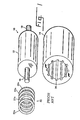
- Fig. 1 there is shown, generally at 10, a schematic representation of pertinent portions of a three-phase generator according to the prior art. Conventional elements of three-phase generator 10, which are unnecessary to a description of the invention, are omitted from the figure.
- a cylindrical rotor 12 is rotatably supported inside an annular armature 14 by conventional bearings, not shown, using shafts 16 and 18.
- a plurality of slots 20 in an interior of armature 14 contain one or more conductor bars (not shown) extending in straight runs parallel to the longitudinal axis of armature 14. Each end of each conductor bar is connected to a selected end of another conductor bar, using an end turn, in a pattern that, in the aggregate forms connected circuits making up the windings of armature 14.
- connection rings 22 are stacked coaxially at one end of three-phase generator 10 for connection of the three-phase output of three-phase generator 10 from the windings of three-phase generator 10 to external circuits (not shown).
- connection rings 22a, 22b, 22c and 22n are used to connect the three phases of the power plus the neutral connection for all phases to external devices.
- connection ring The full circle of each connection ring is required because the points at which the connections are made thereto are spaced about the circumference of slot 20.
- connection rings 22a, 22b, 22c and 22d are stacked coaxially in four planes at the end of three-phase generator 10, usually supported by tying to support bars in stator frame (not shown).
- the DC output of three-phase generator 10 When rectified, the DC output of three-phase generator 10 contains a substantial ripple component, including higher electrical noise components. In applications requiring very low ripple, or very low noise, means must be provided for reducing the ripple. In low-power devices, filtering using capacitors and/or inductors may provide acceptable levels of output ripple. In high-power devices, the size, weight and cost of filter components makes their use unattractive.
- One alternative includes providing more than one set of three-phase windings phase-displaced about the circumference of armature 14. That is, two or more sets of three-phase windings are disposed in slots 20 and connected for external access.
- Figs. 2A-2D four separate three-phase windings 24 (Fig. 2A), 26 (Fig. 2B), 28 (Fig. 2C) and 30 (Fig. 2D) are disposed in slots 20 with a phase displacement therebetween.
- a phase displacement of 15 electrical degrees is illustrated. That is, the relative phase of three-phase winding 24 is arbitrarily identified as zero electrical degrees, that of three-phase winding 2.6 is 15 electrical degrees, that of three-phase winding 28 is 30 electrical degrees and that of three-phase winding 30 is 45 electrical degrees.
- the characteristic harmonic in the ripple in the rectified DC output is much higher in frequency and much lower in amplitude than is the case for the single three-phase winding assumed to be placed in three-phase generator 10 of Fig. 1.
- each of the sets of three phase windings requires four connection rings.
- a total of sixteen connection rings must be disposed in sixteen planes.
- Such a large number of connection rings must be supported and mutually insulated.
- the large cantilevered mass, occupying about 24 axial inches, cannot be supported on end turns, as can the four connection rings 22 of a three-phase machine.
- additional supporting equipment must be designed and built.
- the substantial extra length would increase substantially the overall length of three-phase generator 10.
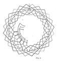
- a wave winding 32 consists of conductor bars 34 laid into slots 20 and connected together by end turns 35. As seen in the figure, the connection of successive conductor bars 34 is progressive, whereby slots 20 in substantially the entire circumference of armature 14 receive conductor bars 34. In one embodiment of the invention two complete passes are taken about the circumference of armature 14 by the same winding.
- Fig. 3 covers only one phase windings of one of the four sets of three phase windings.
- Other, unillustrated, conductor bars 34 are laid in others of the slots 20 to form the remaining two windings making up the three-phase set with wave winding 32.
- the two remaining phase windings associated with the one illustrated phase winding, plus nine other phase windings for the other three sets of three pase windings are wave wound in slots 20 in their relative phase positions about the circumference of armature 14.
- FIG. 4 there is shown, generally at 36, a wave-wound four-winding three-phase generator according to an embodiment of the invention.
- a first stack of connector quadrants 38a, 38b, 38c and 38d are disposed in parallel planes to receive the three phases and the neutral connections of one of the four three-phase windings in armature 14.
- a second stack of connector quadrants 40a, 40b, 40c and 40d are disposed in common planes with their similarly-suffixed counterparts in the first stack to received the three phases and neutral connections of another of the four three-phase windings.
- third and fourth stacks of connector quadrants 42 and 44 occupy the remaining quadrant positions.
- each plane permits connection to corresponding phases of all of the four three phase windings of wave-wound four-winding three-phase generator 36. Accordingly, connections are provided for the twelve phases and four neutrals in the same space as is required for connection for the three phases and one neutral using conventional connection rings 22 of Fig. 1.
- the connector quadrants could more accurately be referred to as connector sectors.
- the connector sectors may depart from the form of a portion of an annulus.
- an angled piece of conductive metal may suffice for providing connection to at least some of the phases. It is believed that an angle piece can be identified as a connector sector, and such a relationship should be read into the present description and claims.
- Fig. 5 shown the routing of conductor bars 34 through a 96-slot armature 14 for one of the three-phase windings, and the connection of the phases and neutral to its respective connector quadrants.
- Figs. 6-8 show routing and connections for the remaining three three-phase windings.
- the present invention is not limited to a device including four three-phase windings.
- two phase-displaced three-phase windings are employed.
- the two-winding device although it reduces ripple in a rectified output, may require further smoothing of the rectified output using, for example, a large inductor, to attain very low levels of ripple.
- the size, weight and cost of such a large inductor makes the two-winding embodiment less attractive than the four-winding alternative.
- Three-winding, five-winding, and other numbers of three phase windings would be drawn to mind of one skilled in the art with the present disclosure for reference.
- the present invention defines a polyphase system, of which a three-phase device is only illustrative. Two phases and four or more phases may be employed in each winding without departing from the spirit and scope of the invention.
Landscapes
- Engineering & Computer Science (AREA)
- Power Engineering (AREA)
- Windings For Motors And Generators (AREA)
- Synchronous Machinery (AREA)
Applications Claiming Priority (2)
| Application Number | Priority Date | Filing Date | Title |
|---|---|---|---|
| US275486 | 1981-06-19 | ||
| US07/275,486 US4914335A (en) | 1988-11-23 | 1988-11-23 | Phase-displaced multiple polyphase dynamoelectric machine with wave windings |
Publications (1)
| Publication Number | Publication Date |
|---|---|
| EP0370166A1 true EP0370166A1 (de) | 1990-05-30 |
Family
ID=23052504
Family Applications (1)
| Application Number | Title | Priority Date | Filing Date |
|---|---|---|---|
| EP89112522A Ceased EP0370166A1 (de) | 1988-11-23 | 1989-07-08 | Dynamoelektrische Maschine mit mehreren phasenverschobenen Mehrphasensystemen, ausgeführt als Wellenwicklungen |
Country Status (5)
| Country | Link |
|---|---|
| US (1) | US4914335A (de) |
| EP (1) | EP0370166A1 (de) |
| JP (1) | JPH02151235A (de) |
| KR (1) | KR900008738A (de) |
| CN (1) | CN1043046A (de) |
Cited By (2)
| Publication number | Priority date | Publication date | Assignee | Title |
|---|---|---|---|---|
| EP1109289A3 (de) * | 1999-12-14 | 2002-08-14 | Mitsubishi Denki Kabushiki Kaisha | Kontaktierung von Statorwicklungen eines Generators |
| EP2800248A1 (de) * | 2013-04-30 | 2014-11-05 | Alstom Technology Ltd | Statorwicklung eines elektrischen Generators |
Families Citing this family (16)
| Publication number | Priority date | Publication date | Assignee | Title |
|---|---|---|---|---|
| KR940001176B1 (ko) * | 1990-07-19 | 1994-02-16 | 가부시끼가이샤 도시바 | 3상 전기자 권선 |
| JP3120185B2 (ja) * | 1991-07-16 | 2000-12-25 | セイコーインスツルメンツ株式会社 | コアレスモータ |
| US5422545A (en) * | 1993-08-19 | 1995-06-06 | Tek-Tron Enterprises, Inc. | Closed loop feedback control circuits for gas discharge lamps |
| US5874822A (en) * | 1994-05-20 | 1999-02-23 | Navarro; Jesus N. | High amperage stator for charging systems in parallel |
| US6054837A (en) * | 1994-06-28 | 2000-04-25 | Borealis Technical Limited | Polyphase induction electrical rotating machine |
| CN1045143C (zh) * | 1994-08-01 | 1999-09-15 | 中国人民解放军海军工程学院 | 三相交流和多相整流同时供电的同步发电机 |
| US6570361B1 (en) * | 1999-02-22 | 2003-05-27 | Borealis Technical Limited | Rotating induction apparatus |
| US5955807A (en) * | 1997-04-25 | 1999-09-21 | Denso Corporation | Synchronous electric machine having auxiliary permanent magnet |
| US6864661B2 (en) * | 1999-02-22 | 2005-03-08 | Borealis Technical Limited | Rotating induction apparatus |
| US6922037B2 (en) * | 1999-02-22 | 2005-07-26 | Borealis Technical Limited | Rotating induction apparatus |
| US6252324B1 (en) * | 1999-04-22 | 2001-06-26 | Borealis Technical Limited | Method of winding a rotating induction apparatus |
| JP3155534B1 (ja) * | 2000-01-20 | 2001-04-09 | 三菱電機株式会社 | 交流発電機の固定子 |
| KR100973686B1 (ko) * | 2008-06-23 | 2010-08-03 | 전자부품연구원 | 코어리스 모터의 고정자 |
| JP5332347B2 (ja) * | 2008-06-30 | 2013-11-06 | 株式会社デンソー | 回転電機のコイル組立体用のコイル線材 |
| US9416761B2 (en) * | 2014-09-30 | 2016-08-16 | Caterpillar Inc. | Nine phase induction motor starter/alternator |
| JP6046180B2 (ja) * | 2015-01-28 | 2016-12-14 | ファナック株式会社 | 3層の巻線構造を有する電動機 |
Citations (3)
| Publication number | Priority date | Publication date | Assignee | Title |
|---|---|---|---|---|
| DE125922C (de) * | ||||
| DE911288C (de) * | 1941-01-08 | 1954-05-13 | Siemens Ag | Mehrphasiger Wechselstromerzeuger |
| FR1549957A (de) * | 1968-01-04 | 1968-12-13 |
Family Cites Families (11)
| Publication number | Priority date | Publication date | Assignee | Title |
|---|---|---|---|---|
| US1356936A (en) * | 1917-05-31 | 1920-10-26 | Gen Electric | Induction-motor |
| DE1080676B (de) * | 1958-04-02 | 1960-04-28 | Siemens Ag | Wechselstrom-Wellenwicklung |
| US3621311A (en) * | 1969-02-20 | 1971-11-16 | Aeg Elotherm Gmbh | Multiphase double-layer winding for electromagnetic pumps and conveyor troughs |
| DE2310380B2 (de) * | 1973-03-02 | 1976-05-20 | Robert Bosch Gmbh, 7000 Stuttgart | Gleichstrommotor |
| DE2348641A1 (de) * | 1973-09-27 | 1975-04-24 | Siemens Ag | Straehnenwicklung fuer elektrische maschinen oder apparate |
| US4132914A (en) * | 1975-04-22 | 1979-01-02 | Khutoretsky Garri M | Six-phase winding of electric machine stator |
| JPS5239105A (en) * | 1975-09-23 | 1977-03-26 | Toshiba Corp | Armature winding of ac rotary machine |
| NL163075C (nl) * | 1976-07-12 | 1980-07-15 | Gils Adrianus Van | Gelamineerde wikkeling voor elektrische machines. |
| US4331896A (en) * | 1980-10-20 | 1982-05-25 | Sedgewick Richard D | Zig-zag windings, winding machine, and method |
| JPS58175940A (ja) * | 1982-04-05 | 1983-10-15 | Nippon Denso Co Ltd | 三相扁平コイル |
| US4675591A (en) * | 1985-04-19 | 1987-06-23 | A. O. Smith Corporation | Induction motor winding |
-
1988
- 1988-11-23 US US07/275,486 patent/US4914335A/en not_active Expired - Fee Related
-
1989
- 1989-07-08 EP EP89112522A patent/EP0370166A1/de not_active Ceased
- 1989-07-19 JP JP1184879A patent/JPH02151235A/ja active Pending
- 1989-07-22 CN CN89106148A patent/CN1043046A/zh active Pending
- 1989-07-22 KR KR1019890010415A patent/KR900008738A/ko not_active Withdrawn
Patent Citations (3)
| Publication number | Priority date | Publication date | Assignee | Title |
|---|---|---|---|---|
| DE125922C (de) * | ||||
| DE911288C (de) * | 1941-01-08 | 1954-05-13 | Siemens Ag | Mehrphasiger Wechselstromerzeuger |
| FR1549957A (de) * | 1968-01-04 | 1968-12-13 |
Cited By (3)
| Publication number | Priority date | Publication date | Assignee | Title |
|---|---|---|---|---|
| EP1109289A3 (de) * | 1999-12-14 | 2002-08-14 | Mitsubishi Denki Kabushiki Kaisha | Kontaktierung von Statorwicklungen eines Generators |
| EP2800248A1 (de) * | 2013-04-30 | 2014-11-05 | Alstom Technology Ltd | Statorwicklung eines elektrischen Generators |
| US9231447B2 (en) | 2013-04-30 | 2016-01-05 | Alstom Technology Ltd | Stator winding of an electric generator |
Also Published As
| Publication number | Publication date |
|---|---|
| US4914335A (en) | 1990-04-03 |
| CN1043046A (zh) | 1990-06-13 |
| JPH02151235A (ja) | 1990-06-11 |
| KR900008738A (ko) | 1990-06-04 |
Similar Documents
| Publication | Publication Date | Title |
|---|---|---|
| US4914335A (en) | Phase-displaced multiple polyphase dynamoelectric machine with wave windings | |
| US4132914A (en) | Six-phase winding of electric machine stator | |
| US7088027B2 (en) | Rotating asynchronous converter and a generator device | |
| US4517471A (en) | Rotary converter machine for direct transfer of electric energy by flux linkage between windings on a stator pack | |
| CA1163665A (en) | Polyphase electric machine having controlled magnetic flux density | |
| US5654602A (en) | Generator winding | |
| US3201627A (en) | Polyphase generators | |
| US6114790A (en) | Sixteen and thirty two slot three phase induction motor winding | |
| US5559385A (en) | Stator of ac electric machine | |
| US4409507A (en) | Dynamoelectric machines for multiples of three phases with unbalanced fractional-slot windings | |
| CA2367389A1 (en) | A constant-frequency machine with a varying/variable speed | |
| US3204167A (en) | Electric motor winding arrangement | |
| JP3550847B2 (ja) | 回転電機の電機子巻線パターン | |
| US3152273A (en) | Polyphase generator windings provided with three parallel connected circuits per phase | |
| EP1914865A2 (de) | Elektrische rotierende Maschine | |
| US3739213A (en) | Compact connection system for polyphase armature winding | |
| US3476964A (en) | Multiple circuit armature winding for polyphase dynamoelectric machine | |
| RU2050666C1 (ru) | 3/1-фазная электромашинная совмещенная обмотка | |
| RU2050667C1 (ru) | Совмещенная электромашинная обмотка | |
| JP3578939B2 (ja) | 回転電機の巻線方法および回転電機 | |
| US5374867A (en) | Coreless motor | |
| US4910421A (en) | Potential source excitation system with voltage and current adjustment | |
| US3366813A (en) | Rotating electrical machine, preferably high power machine | |
| US11374455B2 (en) | Rotary electric machine | |
| US12334788B2 (en) | Stator connection configurations |
Legal Events
| Date | Code | Title | Description |
|---|---|---|---|
| PUAI | Public reference made under article 153(3) epc to a published international application that has entered the european phase |
Free format text: ORIGINAL CODE: 0009012 |
|
| AK | Designated contracting states |
Kind code of ref document: A1 Designated state(s): CH DE FR GB IT LI SE |
|
| 17P | Request for examination filed |
Effective date: 19901114 |
|
| 17Q | First examination report despatched |
Effective date: 19921001 |
|
| STAA | Information on the status of an ep patent application or granted ep patent |
Free format text: STATUS: THE APPLICATION HAS BEEN REFUSED |
|
| 18R | Application refused |
Effective date: 19931010 |