EP0370396A2 - Pieux de support de charge en béton armé à plusieurs branches et base élargie, et moyens pour former le pieu - Google Patents
Pieux de support de charge en béton armé à plusieurs branches et base élargie, et moyens pour former le pieu Download PDFInfo
- Publication number
- EP0370396A2 EP0370396A2 EP89121260A EP89121260A EP0370396A2 EP 0370396 A2 EP0370396 A2 EP 0370396A2 EP 89121260 A EP89121260 A EP 89121260A EP 89121260 A EP89121260 A EP 89121260A EP 0370396 A2 EP0370396 A2 EP 0370396A2
- Authority
- EP
- European Patent Office
- Prior art keywords
- pile
- forming
- cavity
- pressing device
- chisel
- Prior art date
- Legal status (The legal status is an assumption and is not a legal conclusion. Google has not performed a legal analysis and makes no representation as to the accuracy of the status listed.)
- Granted
Links
Images


Classifications
-
- E—FIXED CONSTRUCTIONS
- E02—HYDRAULIC ENGINEERING; FOUNDATIONS; SOIL SHIFTING
- E02D—FOUNDATIONS; EXCAVATIONS; EMBANKMENTS; UNDERGROUND OR UNDERWATER STRUCTURES
- E02D5/00—Bulkheads, piles, or other structural elements specially adapted to foundation engineering
- E02D5/22—Piles
- E02D5/34—Concrete or concrete-like piles cast in position ; Apparatus for making same
- E02D5/38—Concrete or concrete-like piles cast in position ; Apparatus for making same making by use of mould-pipes or other moulds
- E02D5/44—Concrete or concrete-like piles cast in position ; Apparatus for making same making by use of mould-pipes or other moulds with enlarged footing or enlargements at the bottom of the pile
Definitions
- This invention relates to a reinforced concrete load-bearing pile, especially used for consolidating foundations of buildings and bridges or other foundations, and means and method for forming the pile.
- the object of the invention is to provide a reinforced concrete load-bearing pile with multi-branches and enlarged footings for consolidating foundations and means and method for forming such a pile, to overcome the disadvantages in the prevailing technique.
- a reinforced concrete load-bearing pile according to the present invention comprises a pile body, at least one branch and enlarged footing which are integrated with the pile body.
- Means for forming the load-bearing pile comprises a pile cavity drilling/pressing device, a branch cavity pressing device and an enlarged footing cavity pressing device.
- the pile cavity drilling/pressing device is firstly used to form a main pile cavity; then, the branch cavity pressing device and the enlarged footing cavity pressing device are successively used to form at least one branch cavity and enlarged footing cavity; after the whole pile cavity is completed, reinforcing steel bars may be placed into the cavity and casting is carried out.
- a reinforced concrete load-bearing pile comprises a pile body, at least one branch and enlarged footing which are integrated with the pile body.
- the branches can be connected to any part of the pile body, preferably arranged in groups along the axis of the pile body.
- the branches of each group are preferably staggered with those of adjacent groups.
- the numbers of groups and branches in each group are determined according to the condition of ground, building, etc.
- the pile body may consist of a concrete pipe with correspondingly arranged openings for forming branches, and a core.
- the enlarged footings can be connected with the pile body, e.g., at the bottom end of the pile body. The enlarged footing, together with all the branches provides a larger supporting area, thus ensuring higher load-bearing capability of the pile.
- the load-bearing pile according to the present invention can be wholly or partly casted-in-place after a corresponding cavity is formed.
- Means for forming the pile comprises a piie cavity drilling/pressing device, a branch cavity pressing device and an enlarged footing cavity pressing device.
- the pile cavity drilling/pressing device can be used to form a cavity for the pile body. It consists of a pipe body with a blade portion provided at one end and strengthening portion at the end part of the blade portion. There can be at least one opening provided on the pipe body used for forming branch cavities. In order to remove soil inside the pipe body to form the pile cavity, means such as an earth auger with screw blades can be provided. In case of soft ground, a movable conical head is provided at the beginning end of the pipe body forming the pile cavity without removing any soil.
- a modified structure of the device may have a spiral cutting blade connected to the outside of the pipe body.
- the branch cavity pressing device can be either single-armed or multi-armed.
- Each arm has a chisel bearing, a support connected to the bearing bottom and a chisel which is arranged inside the bearing and composed of flexibly connected a chisel end, power transmitting parts and a chisel head.
- a movable support can be futher provided at the bottoms of the supports for positioning and supporting, and the chisel bearings can be connected or integrated.
- the said support of the device guides the direction of the chisel head.
- the transmilting parts can be balls preferably.
- the enlarged footing cavity pressing device comprises a column with a collar fixed at one end and two collars slidably mounted thereon, pairs of pivoted arms pivots with the collars at the same side of the column, a sleeve is slidably provided on the other end of the column.
- two pairs of pivoted arms are arranged symmetrically.
- branches 2 are obliquely integrated with a pile body 1, which comprises a concrete pipe 4 and a core 5.
- the concrete pipe 4 may be embeded reinforcing steel.
- the branches 2 are arranged in pairs along the pile body 1.
- the two branches 2 in each pair are symmetrically arranged and staggered with those in adjacent pairs.
- An enlarged footing 3 connects to the bottom end of the pile body 1.
- Fig. 2 shows a pile cavity drilling/pressing device which is in the form of a pipe.
- a blade portion 11 is provided at one end of the pipe body 14. The thickness of the pipe wall increases from the blade end.
- a strengthening portion which is in the form of a round collar 12, is provided.
- At least one opening 13 can be provided on the pipe body 14 for forming branch cavities.
- the device can be used for either soft ground or stiff ground, preferably for firm ground. It can be driven into ground by pressing.
- Fig. 3 shows a modified pile cavity drilling/pressing device, which is preferred for soft ground.
- This device is further provided with a spiral cutting blade 23 connected to the outside of the pipe body.
- Means for removing soil such as an earth auger or a pump (not shown) is provided; or a movable conical head 25 is provided at the blade end of the pipe body to form a pile cavity without removal of any soil.
- This device can be driven into ground by rotating.
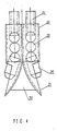
- Fig. 4 shows a preferred embodiment of a branch cavity pressing device which is symmetrically twin-armed.
- Each of the arm has a chisel bearing 30, a support 31 connected to the bearing bottom, and a chisel arranged in the cavity of the chisel bearing 30 and composed of flexibly connected a chisel end 32, power transmitting balls 33 and a chisel head 34.
- a movable support 35 is provided at the bottoms of the supports 31.
- the supports 31 are obliquely arranged and can be used as guides.
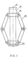
- Fig. 5 shows a preferred enlarged footing cavity pressing device.
- a fixed collar 42 is provided at one end of a column 37.
- Two collars 39 slidably mounted on the column 37.
- a pair of pivoted arms 40 pivot with the movable collars 39 at the same side of the column 37, and another pair of arms 40 at the other side. The said two pairs of arms are symmetricaly arranged.
- a sleeve 38 is slidably mounted at the other end of the column 37. As the sleeve 38 moves downwardly, the pivoted arms 40 are folded. Thus, the radial dimension of the device is increased.
- a pile cavity is firstly formed. Then branch cavities and enlarged footing cavities are to be formed. As a cavity of the pile is completed, reinforcing steel can be put in and casting-in-place can be carried out.
- the pile cavity drilling/pressing device can be used to form the pile cavity.
- Either a pipe type device or a screw type device can be used according to the degree of compactness of the soil.
- the device can be driven into the ground either vertically or at an angle of inclination.
- An earth auger 24 is used to take out the soil (or a mud pump can be used to pump out the mud).
- a movable conical head 25 is mounted at the beginning part of the device, a pile cavity may be formed without taking out the soil. If the ground is stiff, the pile drilling/pressing device can be taken out when the cavity is made.
- the branch cavities can be made through the openings on the pipe body, and the enlarged footing cavities can also be made at the end of the pipe body.
- the pile drilling/pressing device may be withdrawn first, and a precast concrete tube 4 is put in instead. Then the branch cavities and the enlarged footing cavities are made.
- the chisel head 34 of the branch cavity pressing device is directed to either the openings 13 on the pipe body 14 of the drilling/pressing device (there may be a pair of openings at one level and another pair of openings at different positions of a different level), or to the openings provided on the precast concrete pipe 4. Pressure is applied at the chisel end 32.
- the chisel head 34 can be taken out at any time for filling consolidating material (soilid waste, backfill, etc), so that the surroundings and base of the branch cavities can be consolidated.
- consolidating material so that the surroundings and base of the branch cavities can be consolidated.
- the enlarged footing cavity pressing device is introduced into the pile cavity to a predetermined depth (there can be more than one enlarged footing for one pile), then,the pressing sleeve 38 is pressed continually while the device is rotated.
- the pivoted arms 40 may form a cavity for the enlarged footing after the device being rotated 180°.
- Enlarged footing may also be made with the branch cavity pressing device by turning the chisel bearing 30 while pressing the chisel end 32, getting the same effect as using the enlarged footing cavity pressing device.
- filling materials may be added, and the base may be compacted by means of rammers so as to increase the degree of compactness of the soil layer.
- the branches and enlarged footing cavities reinforcing steel bars may be placed into the cavity and concrete may be cast.
- Branches may be precasted. When the branch cavities are made, the precasted branches may be put into place by means of the branch cavity pressing device. The pile can finally be casted.
Landscapes
- Engineering & Computer Science (AREA)
- Structural Engineering (AREA)
- Life Sciences & Earth Sciences (AREA)
- General Life Sciences & Earth Sciences (AREA)
- Mining & Mineral Resources (AREA)
- Paleontology (AREA)
- Civil Engineering (AREA)
- General Engineering & Computer Science (AREA)
- Piles And Underground Anchors (AREA)
Applications Claiming Priority (2)
| Application Number | Priority Date | Filing Date | Title |
|---|---|---|---|
| CN88220149U CN2046512U (zh) | 1988-11-22 | 1988-11-22 | 预制钢筋混凝土花管、分支承载桩施工装置 |
| CN88220149 | 1988-11-22 |
Publications (3)
| Publication Number | Publication Date |
|---|---|
| EP0370396A2 true EP0370396A2 (fr) | 1990-05-30 |
| EP0370396A3 EP0370396A3 (fr) | 1991-04-03 |
| EP0370396B1 EP0370396B1 (fr) | 1993-06-09 |
Family
ID=4852424
Family Applications (1)
| Application Number | Title | Priority Date | Filing Date |
|---|---|---|---|
| EP19890121260 Expired - Lifetime EP0370396B1 (fr) | 1988-11-22 | 1989-11-17 | Pieux de support de charge en béton armé à plusieurs branches et base élargie, et moyens pour former le pieu |
Country Status (4)
| Country | Link |
|---|---|
| EP (1) | EP0370396B1 (fr) |
| JP (1) | JPH02243820A (fr) |
| CN (1) | CN2046512U (fr) |
| CA (1) | CA2003376C (fr) |
Cited By (7)
| Publication number | Priority date | Publication date | Assignee | Title |
|---|---|---|---|---|
| WO1999025930A1 (fr) * | 1997-11-13 | 1999-05-27 | Kvaerner Cementation Foundations Limited | Procedes et appareil ameliores de forage et de battage de pieux |
| WO2000003113A1 (fr) * | 1998-07-10 | 2000-01-20 | Dexin He | Dispositif de pression-expansion hydraulique |
| CN111501740A (zh) * | 2020-06-04 | 2020-08-07 | 刘家赫 | 一种改进型现浇cfg桩与其复合地基结构及其施工方法 |
| CN111927323A (zh) * | 2020-08-28 | 2020-11-13 | 周冲 | 旋挖竹节桩施工方法及其装置 |
| CN113775092A (zh) * | 2021-11-12 | 2021-12-10 | 中冶建筑研究总院有限公司 | 一种王字形钢梁支撑预制板装配式组合楼盖及其建筑物 |
| CN114277835A (zh) * | 2022-03-07 | 2022-04-05 | 中国海洋大学 | 加固海床的抗拔灌注桩及其施工方法 |
| CN118855385A (zh) * | 2024-07-05 | 2024-10-29 | 西安理工大学 | 一种电力振动、钻进、液压挤扩孔的振、夯、压设备 |
Families Citing this family (5)
| Publication number | Priority date | Publication date | Assignee | Title |
|---|---|---|---|---|
| CN100393947C (zh) * | 2006-06-05 | 2008-06-11 | 马金五 | 夯扩承力盘桩的施工方法 |
| CN101139834B (zh) | 2007-08-02 | 2010-05-26 | 夏良站 | 混凝土桩结构 |
| CN101768962B (zh) * | 2009-01-05 | 2013-09-25 | 吴保全 | 预制花管桩 |
| JP2019007149A (ja) * | 2017-06-21 | 2019-01-17 | 菱建基礎株式会社 | フリクションカットケーシング |
| CN113818470B (zh) * | 2021-09-20 | 2023-05-02 | 肇庆市建筑工程有限公司 | 一种建筑施工基桩 |
Family Cites Families (13)
| Publication number | Priority date | Publication date | Assignee | Title |
|---|---|---|---|---|
| US1443306A (en) * | 1919-08-05 | 1923-01-23 | Blumenthal Maurice | Means for and method of producing concrete piles |
| US1521522A (en) * | 1923-12-05 | 1924-12-30 | Fowler Charles Evan | Caisson and method of making the same |
| GB331945A (en) * | 1929-04-19 | 1930-07-17 | Callenders Cable & Const Co | Improvements connected with the production of foundations for poles and the like |
| FR1427486A (fr) * | 1965-03-24 | 1966-02-04 | Gnii Keramzitu | Dispositif pour créer des empattements locaux dans les puits à pieux coulés dans des sols liés |
| DE2436093A1 (de) * | 1974-07-24 | 1976-02-12 | Mannesmann Roehren Werke Ag | Rammpfahl mit einbringbaren spreizgliedern |
| JPS5358105A (en) * | 1976-11-08 | 1978-05-25 | Nippon Concrete Ind Co Ltd | Method of generating supporting force for middle excavation system |
| JPS5433313A (en) * | 1977-08-17 | 1979-03-12 | Marugo Kk | Concrete pile |
| JPS54161715A (en) * | 1978-06-12 | 1979-12-21 | Kazuhiro Kawase | Foundation pillar and method of executing foundation pillar |
| JPS55155825A (en) * | 1979-05-23 | 1980-12-04 | Marugo Kiso Kogyo Kk | Burying method for pile with extension shoe |
| JPS5634823A (en) * | 1979-08-30 | 1981-04-07 | Touparu Gijutsu Kenkyusho:Kk | Concrete pile injection constructing method |
| JPS57193621A (en) * | 1981-05-23 | 1982-11-29 | Tadayoshi Fujimatsu | In-place reinforced concrete expanded bottom foundation pile and its construction and bit therefore |
| JPS62160315A (ja) * | 1985-12-30 | 1987-07-16 | Kajima Corp | 杭の埋込み工法 |
| JP3573794B2 (ja) * | 1994-06-20 | 2004-10-06 | 三洋電機株式会社 | 温風暖房機 |
-
1988
- 1988-11-22 CN CN88220149U patent/CN2046512U/zh not_active Expired - Lifetime
-
1989
- 1989-11-17 EP EP19890121260 patent/EP0370396B1/fr not_active Expired - Lifetime
- 1989-11-20 CA CA 2003376 patent/CA2003376C/fr not_active Expired - Fee Related
- 1989-11-22 JP JP30450889A patent/JPH02243820A/ja active Pending
Cited By (11)
| Publication number | Priority date | Publication date | Assignee | Title |
|---|---|---|---|---|
| WO1999025930A1 (fr) * | 1997-11-13 | 1999-05-27 | Kvaerner Cementation Foundations Limited | Procedes et appareil ameliores de forage et de battage de pieux |
| GB2331318B (en) * | 1997-11-13 | 2001-05-16 | Kvaerner Cementation Found Ltd | Improved methods and apparatus for boring and piling |
| US6402432B1 (en) | 1997-11-13 | 2002-06-11 | Kvaerner Cementation Foundations Limited | Method for installing load bearing piles utilizing a tool with blade means |
| WO2000003113A1 (fr) * | 1998-07-10 | 2000-01-20 | Dexin He | Dispositif de pression-expansion hydraulique |
| CN1057363C (zh) * | 1998-07-10 | 2000-10-11 | 贺德新 | 一种液压挤扩装置 |
| CN111501740A (zh) * | 2020-06-04 | 2020-08-07 | 刘家赫 | 一种改进型现浇cfg桩与其复合地基结构及其施工方法 |
| CN111927323A (zh) * | 2020-08-28 | 2020-11-13 | 周冲 | 旋挖竹节桩施工方法及其装置 |
| CN113775092A (zh) * | 2021-11-12 | 2021-12-10 | 中冶建筑研究总院有限公司 | 一种王字形钢梁支撑预制板装配式组合楼盖及其建筑物 |
| CN113775092B (zh) * | 2021-11-12 | 2022-02-08 | 中冶建筑研究总院有限公司 | 一种王字形钢梁支撑预制板装配式组合楼盖及其建筑物 |
| CN114277835A (zh) * | 2022-03-07 | 2022-04-05 | 中国海洋大学 | 加固海床的抗拔灌注桩及其施工方法 |
| CN118855385A (zh) * | 2024-07-05 | 2024-10-29 | 西安理工大学 | 一种电力振动、钻进、液压挤扩孔的振、夯、压设备 |
Also Published As
| Publication number | Publication date |
|---|---|
| EP0370396A3 (fr) | 1991-04-03 |
| CN2046512U (zh) | 1989-10-25 |
| CA2003376C (fr) | 1999-07-27 |
| JPH02243820A (ja) | 1990-09-27 |
| EP0370396B1 (fr) | 1993-06-09 |
| CA2003376A1 (fr) | 1990-05-22 |
Similar Documents
| Publication | Publication Date | Title |
|---|---|---|
| US4405262A (en) | Method for erection of a temporary bridge, and a pile means therefor | |
| US7326004B2 (en) | Apparatus for providing a rammed aggregate pier | |
| US8221034B2 (en) | Methods of providing a support column | |
| EP0370396B1 (fr) | Pieux de support de charge en béton armé à plusieurs branches et base élargie, et moyens pour former le pieu | |
| US9243379B2 (en) | Method of providing a support column | |
| US4293242A (en) | Piles | |
| US3250075A (en) | Method of retaining wall construction and anchoring | |
| US4834582A (en) | Methods for underpinning unstable structures | |
| EP1041240B1 (fr) | Fleuret hélicoidal | |
| US5122013A (en) | Reinforced concrete load-bearing pile with multi-branches and enlarged footings, and means and method for forming the pile | |
| US5219249A (en) | Reinforced concrete load-bearing pile forming device | |
| GB2329204A (en) | Earth auger | |
| KR101765879B1 (ko) | 지반보강용 합성블록체 및 이를 이용한 기초저면의 보강공법 | |
| JPH05306518A (ja) | 鋼管杭用掘削機と該掘削機を備えた鋼管杭用掘削装置および鋼管杭の施工方法 | |
| CN213173700U (zh) | 一种用于软基处理的预制桩 | |
| GB2132667A (en) | Method of installing precast concrete piles | |
| JPH0913372A (ja) | 杭工法 | |
| JPH0280710A (ja) | 場所打コンクリート杭の造成工法 | |
| JP2000345554A (ja) | 地盤改良方法 | |
| CN2199240Y (zh) | 建筑基础工艺基坑倾斜围护桩 | |
| CN2346836Y (zh) | 钢筋砼大截面空心方桩 | |
| KR900005913B1 (ko) | 기초 말뚝 및 그 공법 | |
| CN215471979U (zh) | 一种管桩生产下料辅助装置 | |
| JP2001011874A (ja) | 既製杭を使用した構真柱の構築方法 | |
| JP2001011860A (ja) | 既製杭を使用した構真柱の構築方法 |
Legal Events
| Date | Code | Title | Description |
|---|---|---|---|
| PUAI | Public reference made under article 153(3) epc to a published international application that has entered the european phase |
Free format text: ORIGINAL CODE: 0009012 |
|
| AK | Designated contracting states |
Kind code of ref document: A2 Designated state(s): FR GB IT NL |
|
| RAP1 | Party data changed (applicant data changed or rights of an application transferred) |
Owner name: JUNSHENG, ZHANG Owner name: YANQIN, XU |
|
| RIN1 | Information on inventor provided before grant (corrected) |
Inventor name: YANQIN, XU Inventor name: JUNSHENG, ZHANG |
|
| PUAL | Search report despatched |
Free format text: ORIGINAL CODE: 0009013 |
|
| AK | Designated contracting states |
Kind code of ref document: A3 Designated state(s): FR GB IT NL |
|
| 17P | Request for examination filed |
Effective date: 19911001 |
|
| 17Q | First examination report despatched |
Effective date: 19911111 |
|
| GRAA | (expected) grant |
Free format text: ORIGINAL CODE: 0009210 |
|
| AK | Designated contracting states |
Kind code of ref document: B1 Designated state(s): FR GB IT NL |
|
| ITF | It: translation for a ep patent filed | ||
| ET | Fr: translation filed | ||
| PLBE | No opposition filed within time limit |
Free format text: ORIGINAL CODE: 0009261 |
|
| STAA | Information on the status of an ep patent application or granted ep patent |
Free format text: STATUS: NO OPPOSITION FILED WITHIN TIME LIMIT |
|
| 26N | No opposition filed | ||
| REG | Reference to a national code |
Ref country code: GB Ref legal event code: IF02 |
|
| PGFP | Annual fee paid to national office [announced via postgrant information from national office to epo] |
Ref country code: GB Payment date: 20041111 Year of fee payment: 16 |
|
| PGFP | Annual fee paid to national office [announced via postgrant information from national office to epo] |
Ref country code: NL Payment date: 20041117 Year of fee payment: 16 |
|
| PGFP | Annual fee paid to national office [announced via postgrant information from national office to epo] |
Ref country code: FR Payment date: 20041118 Year of fee payment: 16 |
|
| PG25 | Lapsed in a contracting state [announced via postgrant information from national office to epo] |
Ref country code: IT Free format text: LAPSE BECAUSE OF NON-PAYMENT OF DUE FEES;WARNING: LAPSES OF ITALIAN PATENTS WITH EFFECTIVE DATE BEFORE 2007 MAY HAVE OCCURRED AT ANY TIME BEFORE 2007. THE CORRECT EFFECTIVE DATE MAY BE DIFFERENT FROM THE ONE RECORDED. Effective date: 20051117 Ref country code: GB Free format text: LAPSE BECAUSE OF NON-PAYMENT OF DUE FEES Effective date: 20051117 |
|
| PG25 | Lapsed in a contracting state [announced via postgrant information from national office to epo] |
Ref country code: NL Free format text: LAPSE BECAUSE OF NON-PAYMENT OF DUE FEES Effective date: 20060601 |
|
| GBPC | Gb: european patent ceased through non-payment of renewal fee |
Effective date: 20051117 |
|
| PG25 | Lapsed in a contracting state [announced via postgrant information from national office to epo] |
Ref country code: FR Free format text: LAPSE BECAUSE OF NON-PAYMENT OF DUE FEES Effective date: 20060731 |
|
| NLV4 | Nl: lapsed or anulled due to non-payment of the annual fee |
Effective date: 20060601 |
|
| REG | Reference to a national code |
Ref country code: FR Ref legal event code: ST Effective date: 20060731 |