EP0370423A2 - Dispositif pour former un point d'échange dans un réseau de télécommunication - Google Patents
Dispositif pour former un point d'échange dans un réseau de télécommunication Download PDFInfo
- Publication number
- EP0370423A2 EP0370423A2 EP89121409A EP89121409A EP0370423A2 EP 0370423 A2 EP0370423 A2 EP 0370423A2 EP 89121409 A EP89121409 A EP 89121409A EP 89121409 A EP89121409 A EP 89121409A EP 0370423 A2 EP0370423 A2 EP 0370423A2
- Authority
- EP
- European Patent Office
- Prior art keywords
- electronics
- network
- test
- housing
- terminal
- Prior art date
- Legal status (The legal status is an assumption and is not a legal conclusion. Google has not performed a legal analysis and makes no representation as to the accuracy of the status listed.)
- Withdrawn
Links
Images

Classifications
-
- H—ELECTRICITY
- H04—ELECTRIC COMMUNICATION TECHNIQUE
- H04M—TELEPHONIC COMMUNICATION
- H04M1/00—Substation equipment, e.g. for use by subscribers
- H04M1/24—Arrangements for testing
-
- H—ELECTRICITY
- H04—ELECTRIC COMMUNICATION TECHNIQUE
- H04M—TELEPHONIC COMMUNICATION
- H04M3/00—Automatic or semi-automatic exchanges
- H04M3/22—Arrangements for supervision, monitoring or testing
- H04M3/26—Arrangements for supervision, monitoring or testing with means for applying test signals or for measuring
- H04M3/28—Automatic routine testing ; Fault testing; Installation testing; Test methods, test equipment or test arrangements therefor
- H04M3/30—Automatic routine testing ; Fault testing; Installation testing; Test methods, test equipment or test arrangements therefor for subscriber's lines, for the local loop
- H04M3/301—Circuit arrangements at the subscriber's side of the line
Definitions
- the invention relates to a device for forming a transfer point at a connection point and / or at a connection device of a telecommunications network with an electronic circuit in order to switch the electronics into a test completion state via pulses from the general network.
- Such a device is known, for example, from international application WO 85/02740, this circuit being intended to enable the user to determine faults in the transmission line, specifically in the alternative whether the faults are on the network side or on the user side lie.
- this circuit e.g. can be controlled from a mail center from the user side and in the same way also from the network side, voltage-sensitive switches being provided for the switchover.
- the known devices are only possible for switching on and on in the corresponding operating modes, there is a desire to duplicate the performance possibilities of such devices, the known techniques being able to be integrated at the same time.
- the object of the invention is therefore to provide a solution with which the performance of a device of the type described at the outset is increased and thus its range of uses is increased without the advantages of known solutions being prevented, the device device, in particular, should make it possible to check errors at the transition from the general network to the terminal network.
- this object is achieved according to the invention in that the electronic circuit is additionally designed as a test circuit of the terminal network.
- Precise error detection can also be carried out directly from the telecommunication center using the device; the test circuit of the terminal network can e.g. recognize whether the handset of a speaking set is not on-hook, whether there is an electrical fault in the terminal network or whether a terminal set is not connected at all, and the like. Depending on the type of error, the telephone exchange can then switch off the subscriber from the terminal or trigger an immediate remedy.
- the invention provides in an embodiment that the electronic circuit is equipped with a device for recognizing the analog or digital switching technology present in each case. This design makes it possible that the device can be used regardless of the type of operating system, ie can be used in many ways.
- the electronic circuit can be subjected to frequency or voltage impulses at least from the outside and / or when a control signal comes up, the electronics automatically assume the required switching state.
- Another embodiment of the invention is that when activated, the electronics switch on a time stage that enables the switching path for a predetermined time, switching the electronics back to the inactive consumer state in the absence of an encoded voltage pulse or in the absence of an encoded frequency.
- This option can be used, among other things, to avoid unnecessary network blockages, for example by activating the fork switch of a telephone set. If this is activated beyond a predetermined period of time without a dialing pulse following, the electronics according to the invention can switch off the apparatus from the network. When the fork switch is actuated, the device can be arranged so that the test circuit automatically removes the separation.
- the invention also provides that the electronics are provided with their own mains-independent voltage supply, which in the event of a fault makes the electronics independent of an external voltage supply, the supply being designed, for example, as a buffered battery which is independent of the supply network can be.
- the electronics are designed to detect the activation state of the subscriber device and / or if a fault in the area of the subscriber device is detected, this circuit page is switched off, the switched-off page is periodically checked and the circuit page is automatically switched back to the desired use state when the error message is removed and / or that the electronics are equipped with a remotely activated fee lock.
- the electronics are designed in such a way that, depending on the time, they monitor the telecommunication unit for the dialing tone, the dialing, the call acknowledgment, the busy tone and or the language and, if a signal is not recognized or if a predetermined time frame is exceeded, the exchange line is released. This prevents an external line from being blocked excessively, for example by simulating a call, for example by dialing only two numbers and putting the handset aside. After a period has been exceeded Without signal reception, the electronics then clear the line again.
- the electronics form an integral part in the housing of a switch box forming the termination point of the general network and / or the connection device of a terminal, the electronics being housed in a housing which is used to separate the general network and the terminal network sealable different housing areas is designed.
- the housing can be designed in such a way that the electronics and the power supply line are accommodated in the area of the secured and possibly sealed postal area of this housing, sealable housings being known per se.
- the invention also provides that the housing is equipped with a test connection for the one or more terminal networks, the electronics acting on the test connection providing the user with an error detection signal by test routines and / or identifying the error by visual or acoustic display.
- a further embodiment of the invention consists in that in the case of a plurality of terminal network connections in the termination housing of the general network equipped with electronics, the terminal network connections can be inserted into the housing in a modular manner and the electronics for a test routine are designed to be connectable to the test output of the respectively desired terminal network connection module.
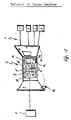
- FIG. 1 shows a network node 1 of a telecommunications network and a terminal network, generally designated 2, with a plurality of terminal network connections which bear the reference numerals 3 to 6.
- the device designated as 7 is also represented symbolically as a transfer point, namely as a two-part housing 8, each with a housing cover 9 or 10.
- the special feature here is that in the housing part 9 closed from the housing part 9 'an electronics 11 is housed with the features described above, the area of the electronics 11 is closed over the housing cover 9 and can be sealed by means of an indicated seal 12.
- a display unit 12 which can be acted upon by the electronics 11 and which can indicate the error messages or other operating states to the user. With 13, some batteries are indicated, which make the electronics 11 independent of a power supply.
- a test connection for checking the terminal network 2 by the respective user or a fitter is indicated and designated 14, it should be in the housing part 10 '.
- 11 denotes the electronic board, which carries all the essential functional elements, for example an LED with an activation switch 15 for an optical display unit 12, which can be activated, for example, when the housing is opened, with buffered batteries 13 and with the test connection 14.
- a voltage converter 16 a charge switch which can be activated remotely by the operator of the system, for example the post, is arranged on the electronics 11 associated with the buffer batteries 17 and a control unit 18 with the functions shown below.
- the charge lock switch 17 that it can be switched by the post office if, for example, the user's telephone charges are not paid, and this is designed in such a way that the switch 19 is closed in a loop when the telephone device is used is chosen. This means that the telephone user can be called at any time, but he himself cannot make calls that generate charges.
- control unit has an analog-to-digital converter 20, a port 21 as a signal input / output, a microprocessor 22, a RAM 23 and a ROM 24, without the invention being restricted to this.
- the elements 22 to 24 could also be designed as microcontrollers that contain a RAM and a ROM.
- switching relay 25 which can be used if necessary to determine errors on the user side.
- S1 denotes a sensor line for potential or polarity relationships on the connecting line
- S2 a control line for an S relay for charge lock or loop
- S3 a sensor line for relay 25, for example for switching off or on the End ask for existing errors or for troubleshooting.
- the user of the invention is evidently enabled to locate faults in his own area.
- the telephone set 2 can be plugged into the test plug 14 after the device has been opened. Can be called from here, it is ensured that the exchange line up to the test connector 14 has no errors.
- Additional information can, for example, be transmitted to the user via the LED display 12, for example in such a way that, although calls cannot be made, an immediate error is visually displayed in the telephone device 2, e.g. upon detection of a short circuit or the like, which also takes place via the relay circuit 25 by means of the microprocessor 22.
- the device can be arranged such that a test routine is carried out automatically when the housing 8 is opened, the user then optically or acoustically, e.g. The status of the outside line is displayed via LED 12, for example whether it is error-free or not. If it is not error-free, the user can automatically be shown immediately whether, for example, a charge block has been set by the office or whether there is another error in the outside line.
Landscapes
- Engineering & Computer Science (AREA)
- Signal Processing (AREA)
- Monitoring And Testing Of Exchanges (AREA)
- Telephonic Communication Services (AREA)
- Small-Scale Networks (AREA)
Applications Claiming Priority (2)
| Application Number | Priority Date | Filing Date | Title |
|---|---|---|---|
| DE3839266 | 1988-11-21 | ||
| DE19883839266 DE3839266A1 (de) | 1988-11-21 | 1988-11-21 | Vorrichtung zur bildung einer uebergabestelle in einem fernmeldenetz |
Publications (2)
| Publication Number | Publication Date |
|---|---|
| EP0370423A2 true EP0370423A2 (fr) | 1990-05-30 |
| EP0370423A3 EP0370423A3 (fr) | 1991-07-03 |
Family
ID=6367557
Family Applications (1)
| Application Number | Title | Priority Date | Filing Date |
|---|---|---|---|
| EP19890121409 Withdrawn EP0370423A3 (fr) | 1988-11-21 | 1989-11-18 | Dispositif pour former un point d'échange dans un réseau de télécommunication |
Country Status (2)
| Country | Link |
|---|---|
| EP (1) | EP0370423A3 (fr) |
| DE (1) | DE3839266A1 (fr) |
Cited By (11)
| Publication number | Priority date | Publication date | Assignee | Title |
|---|---|---|---|---|
| US5111497A (en) * | 1990-09-17 | 1992-05-05 | Raychem Corporation | Alarm and test system for a digital added main line |
| ES2038899A2 (es) * | 1991-07-18 | 1993-08-01 | Telefonica Nacional Espana Co | Punto de terminacion de red. |
| ES2046072A2 (es) * | 1991-06-21 | 1994-01-16 | Telefonica Nacional Espana Co | Punto de conexion de red con modulo de telemedida. |
| US5427547A (en) * | 1990-09-17 | 1995-06-27 | Raychem Corporation | Gel filled modular electrical connecting block |
| US5459729A (en) * | 1989-07-25 | 1995-10-17 | Raychem Corporation | Digital added main line system |
| WO1995032575A2 (fr) | 1994-05-17 | 1995-11-30 | British Telecommunications Public Limited Company | Installation terminale de reseau |
| US5562491A (en) * | 1990-09-17 | 1996-10-08 | Raychem Corporation | Gel filled electrical connector |
| US5598455A (en) * | 1990-09-17 | 1997-01-28 | Raychem Corporation | Alarm and test system for a digital added main line |
| WO1997018686A1 (fr) * | 1995-11-15 | 1997-05-22 | Siemens Schweiz Ag | Douille de connexion pour terminaux de telecommunication |
| US5978390A (en) * | 1995-03-20 | 1999-11-02 | Raychem Corporation | Dual DDS data multiplexer |
| US6282204B1 (en) | 1997-12-19 | 2001-08-28 | Terayon Communication Systems, Inc. | ISDN plus voice multiplexer system |
Family Cites Families (7)
| Publication number | Priority date | Publication date | Assignee | Title |
|---|---|---|---|---|
| US4197435A (en) * | 1978-02-24 | 1980-04-08 | Jackson Amos R | Telephone line monitoring circuit and method |
| DE2816408C2 (de) * | 1978-04-15 | 1985-08-01 | Telefonbau Und Normalzeit Gmbh, 6000 Frankfurt | Schaltungsanordnung zur Prüfung der Teilnehmeranschlüsse einer digitalen zeitmultiplexen Fernsprechvermittlungsanlage |
| US4258236A (en) * | 1979-04-04 | 1981-03-24 | Conklin Instrument Corporation | Remote telephone line switching and testing |
| US4399333A (en) * | 1981-07-30 | 1983-08-16 | Teltec Inc. | Telephone fault detection system |
| DE3240660A1 (de) * | 1982-11-04 | 1984-05-10 | Standard Elektrik Lorenz Ag, 7000 Stuttgart | Pruefverfahren fuer digitale teilnehmerendeinrichtungen und dafuer geeignete teilnehmerendeinrichtung |
| DE3311400A1 (de) * | 1983-03-29 | 1984-10-04 | Standard Elektrik Lorenz Ag, 7000 Stuttgart | Schaltungsanordnung zur pruefung von teilnehmerendeinrichtungen |
| DE3609979A1 (de) * | 1986-03-25 | 1987-10-08 | Quante Fernmeldetechnik Gmbh | Vorrichtung zum ueberwachen von fernsprech-endeinrichtungen auf stoerungen, insbesondere kurzschluss |
-
1988
- 1988-11-21 DE DE19883839266 patent/DE3839266A1/de not_active Ceased
-
1989
- 1989-11-18 EP EP19890121409 patent/EP0370423A3/fr not_active Withdrawn
Cited By (19)
| Publication number | Priority date | Publication date | Assignee | Title |
|---|---|---|---|---|
| US5627833A (en) * | 1989-07-25 | 1997-05-06 | Raychem Corporation | Digital added main line system with power-up and power-down features |
| US5459729A (en) * | 1989-07-25 | 1995-10-17 | Raychem Corporation | Digital added main line system |
| US5473613A (en) * | 1989-07-25 | 1995-12-05 | Raychem Corporation | Digital added main line system |
| US5459730A (en) * | 1989-07-25 | 1995-10-17 | Raychem Corporation | Digital added main line system |
| US5598455A (en) * | 1990-09-17 | 1997-01-28 | Raychem Corporation | Alarm and test system for a digital added main line |
| US5427547A (en) * | 1990-09-17 | 1995-06-27 | Raychem Corporation | Gel filled modular electrical connecting block |
| US5111497A (en) * | 1990-09-17 | 1992-05-05 | Raychem Corporation | Alarm and test system for a digital added main line |
| US5562491A (en) * | 1990-09-17 | 1996-10-08 | Raychem Corporation | Gel filled electrical connector |
| US5601460A (en) * | 1990-09-17 | 1997-02-11 | Raychem Corporation | Gel filled modular electrical connecting block |
| ES2046072A2 (es) * | 1991-06-21 | 1994-01-16 | Telefonica Nacional Espana Co | Punto de conexion de red con modulo de telemedida. |
| ES2038899A2 (es) * | 1991-07-18 | 1993-08-01 | Telefonica Nacional Espana Co | Punto de terminacion de red. |
| WO1995032575A3 (fr) * | 1994-05-17 | 1996-02-08 | British Telecomm | Installation terminale de reseau |
| WO1995032575A2 (fr) | 1994-05-17 | 1995-11-30 | British Telecommunications Public Limited Company | Installation terminale de reseau |
| AU685277B2 (en) * | 1994-05-17 | 1998-01-15 | British Telecommunications Public Limited Company | Network termination equipment |
| US5841836A (en) * | 1994-05-17 | 1998-11-24 | British Telecommunications Public Limited Company | Network termination equipment |
| CN1096172C (zh) * | 1994-05-17 | 2002-12-11 | 英国电讯有限公司 | 网络终端设备 |
| US5978390A (en) * | 1995-03-20 | 1999-11-02 | Raychem Corporation | Dual DDS data multiplexer |
| WO1997018686A1 (fr) * | 1995-11-15 | 1997-05-22 | Siemens Schweiz Ag | Douille de connexion pour terminaux de telecommunication |
| US6282204B1 (en) | 1997-12-19 | 2001-08-28 | Terayon Communication Systems, Inc. | ISDN plus voice multiplexer system |
Also Published As
| Publication number | Publication date |
|---|---|
| EP0370423A3 (fr) | 1991-07-03 |
| DE3839266A1 (de) | 1990-05-23 |
Similar Documents
| Publication | Publication Date | Title |
|---|---|---|
| EP0370423A2 (fr) | Dispositif pour former un point d'échange dans un réseau de télécommunication | |
| EP0923835A1 (fr) | Procede de surveillance et de verification des raccordements d'un reseau rnis de telecommunication | |
| AT398665B (de) | Isdn-abschlusseinrichtung | |
| DE3504046C2 (fr) | ||
| DE2939008C2 (de) | Schaltungsanordnung für eine Teilnehmeranschlußschaltung eines elektronischen Vermittlungssystems | |
| DE3884486T2 (de) | Öffentliches Fernsprechgerät mit permanenter Verbindung. | |
| DE3434172C2 (fr) | ||
| DE3245005C2 (de) | Stromversorgung für eine Schaltungsanordnung zur Wählzeichenstromstoßgabe in einem Fernsprechapparat | |
| EP0589085B1 (fr) | Unité de raccordement d'abonnés pour le raccordement d'un PBX à un système publique de téléphone | |
| DE3707894A1 (de) | Handgeraet zur ueberpruefung von fernmeldeleitungssystemen | |
| DE3506369C2 (fr) | ||
| DE2341246A1 (de) | Elektronische sperreinrichtung fuer nummernschalterwahl zur verhinderung der wahl unerwuenschter waehlziffern | |
| DE9214765U1 (de) | Elektrische Sperrvorrichtung für Telekommunikationsgeräte | |
| EP0954152B1 (fr) | Montage pour mesurer des tensions externes sur des lignes de raccordement dans un module de connexion d' abonné | |
| DE3036657C2 (de) | Teilnehmeranschlußschaltung für Münzfernsprecher mit Schaltmitteln zur Feststellung der einzelnen zu überwachenden Betriebszustände | |
| DE19710348C1 (de) | Vorrichtung zum Anschalten einer Zusatzeinrichtung an eine analoge Endeinrichtung ohne w-Ader | |
| DE3309286C2 (fr) | ||
| DE3606143A1 (de) | Schaltungsanordnung fuer anschlussleitungen von amts- und nebenstellen im fernsprechnetz | |
| DE3418460C2 (fr) | ||
| DE3525106C2 (fr) | ||
| DE3832618C1 (en) | Checkable line termination for a telephone line | |
| DE1562224C3 (de) | Schaltungsanordnung für eine zentral gesteuerte Fernsprechvermittlungsanlage, insbesondere transportable Fernsprechvermittlungsanlage | |
| DE4422976A1 (de) | Verfahren zur Überwachung einer Fernsprechleitung | |
| DE4242855A1 (de) | Schaltungsanordnung zum Anschluß von Alarm- oder Gefahrenmeldern an Anschlußleitungen von Telekommunikations-Endgeräten | |
| CH651981A5 (en) | Circuit arrangement for mains-powered telephone PABX systems |
Legal Events
| Date | Code | Title | Description |
|---|---|---|---|
| PUAI | Public reference made under article 153(3) epc to a published international application that has entered the european phase |
Free format text: ORIGINAL CODE: 0009012 |
|
| AK | Designated contracting states |
Kind code of ref document: A2 Designated state(s): AT BE CH DE ES FR GB GR IT LI NL SE |
|
| PUAL | Search report despatched |
Free format text: ORIGINAL CODE: 0009013 |
|
| AK | Designated contracting states |
Kind code of ref document: A3 Designated state(s): AT BE CH DE ES FR GB GR IT LI NL SE |
|
| 17P | Request for examination filed |
Effective date: 19910604 |
|
| 17Q | First examination report despatched |
Effective date: 19930830 |
|
| STAA | Information on the status of an ep patent application or granted ep patent |
Free format text: STATUS: THE APPLICATION IS DEEMED TO BE WITHDRAWN |
|
| 18D | Application deemed to be withdrawn |
Effective date: 19940111 |