EP0370843A1 - Plateau de polissage - Google Patents
Plateau de polissage Download PDFInfo
- Publication number
- EP0370843A1 EP0370843A1 EP89402889A EP89402889A EP0370843A1 EP 0370843 A1 EP0370843 A1 EP 0370843A1 EP 89402889 A EP89402889 A EP 89402889A EP 89402889 A EP89402889 A EP 89402889A EP 0370843 A1 EP0370843 A1 EP 0370843A1
- Authority
- EP
- European Patent Office
- Prior art keywords
- parts
- length
- total
- hard
- tray according
- Prior art date
- Legal status (The legal status is an assumption and is not a legal conclusion. Google has not performed a legal analysis and makes no representation as to the accuracy of the status listed.)
- Granted
Links
- 238000005498 polishing Methods 0.000 title claims abstract description 10
- 239000011159 matrix material Substances 0.000 claims description 8
- 239000000463 material Substances 0.000 description 8
- 239000011230 binding agent Substances 0.000 description 7
- 229920005989 resin Polymers 0.000 description 6
- 239000011347 resin Substances 0.000 description 6
- RYGMFSIKBFXOCR-UHFFFAOYSA-N Copper Chemical compound [Cu] RYGMFSIKBFXOCR-UHFFFAOYSA-N 0.000 description 5
- 239000003082 abrasive agent Substances 0.000 description 5
- 239000010949 copper Substances 0.000 description 5
- 239000000203 mixture Substances 0.000 description 5
- 229910000881 Cu alloy Inorganic materials 0.000 description 3
- 239000000843 powder Substances 0.000 description 3
- 239000000725 suspension Substances 0.000 description 3
- XEEYBQQBJWHFJM-UHFFFAOYSA-N Iron Chemical compound [Fe] XEEYBQQBJWHFJM-UHFFFAOYSA-N 0.000 description 2
- PNEYBMLMFCGWSK-UHFFFAOYSA-N aluminium oxide Inorganic materials [O-2].[O-2].[O-2].[Al+3].[Al+3] PNEYBMLMFCGWSK-UHFFFAOYSA-N 0.000 description 2
- 229910052802 copper Inorganic materials 0.000 description 2
- 239000010432 diamond Substances 0.000 description 2
- 229910003460 diamond Inorganic materials 0.000 description 2
- 150000002334 glycols Chemical class 0.000 description 2
- 229920001568 phenolic resin Polymers 0.000 description 2
- 229920001225 polyester resin Polymers 0.000 description 2
- XLYOFNOQVPJJNP-UHFFFAOYSA-N water Substances O XLYOFNOQVPJJNP-UHFFFAOYSA-N 0.000 description 2
- HGINCPLSRVDWNT-UHFFFAOYSA-N Acrolein Chemical compound C=CC=O HGINCPLSRVDWNT-UHFFFAOYSA-N 0.000 description 1
- 229920000178 Acrylic resin Polymers 0.000 description 1
- 239000004925 Acrylic resin Substances 0.000 description 1
- 229910000838 Al alloy Inorganic materials 0.000 description 1
- 229910052580 B4C Inorganic materials 0.000 description 1
- 229910001369 Brass Inorganic materials 0.000 description 1
- 229910000906 Bronze Inorganic materials 0.000 description 1
- 229910001018 Cast iron Inorganic materials 0.000 description 1
- VYZAMTAEIAYCRO-UHFFFAOYSA-N Chromium Chemical compound [Cr] VYZAMTAEIAYCRO-UHFFFAOYSA-N 0.000 description 1
- 229910000978 Pb alloy Inorganic materials 0.000 description 1
- ATJFFYVFTNAWJD-UHFFFAOYSA-N Tin Chemical compound [Sn] ATJFFYVFTNAWJD-UHFFFAOYSA-N 0.000 description 1
- HCHKCACWOHOZIP-UHFFFAOYSA-N Zinc Chemical compound [Zn] HCHKCACWOHOZIP-UHFFFAOYSA-N 0.000 description 1
- 229910052782 aluminium Inorganic materials 0.000 description 1
- XAGFODPZIPBFFR-UHFFFAOYSA-N aluminium Chemical compound [Al] XAGFODPZIPBFFR-UHFFFAOYSA-N 0.000 description 1
- 229910052787 antimony Inorganic materials 0.000 description 1
- WATWJIUSRGPENY-UHFFFAOYSA-N antimony atom Chemical compound [Sb] WATWJIUSRGPENY-UHFFFAOYSA-N 0.000 description 1
- INAHAJYZKVIDIZ-UHFFFAOYSA-N boron carbide Chemical compound B12B3B4C32B41 INAHAJYZKVIDIZ-UHFFFAOYSA-N 0.000 description 1
- 239000010951 brass Substances 0.000 description 1
- 239000010974 bronze Substances 0.000 description 1
- QHIWVLPBUQWDMQ-UHFFFAOYSA-N butyl prop-2-enoate;methyl 2-methylprop-2-enoate;prop-2-enoic acid Chemical compound OC(=O)C=C.COC(=O)C(C)=C.CCCCOC(=O)C=C QHIWVLPBUQWDMQ-UHFFFAOYSA-N 0.000 description 1
- 229910052804 chromium Inorganic materials 0.000 description 1
- 239000011651 chromium Substances 0.000 description 1
- KUNSUQLRTQLHQQ-UHFFFAOYSA-N copper tin Chemical compound [Cu].[Sn] KUNSUQLRTQLHQQ-UHFFFAOYSA-N 0.000 description 1
- 239000010431 corundum Substances 0.000 description 1
- 229910052593 corundum Inorganic materials 0.000 description 1
- 229910052742 iron Inorganic materials 0.000 description 1
- 239000003350 kerosene Substances 0.000 description 1
- 239000007788 liquid Substances 0.000 description 1
- 238000004519 manufacturing process Methods 0.000 description 1
- 229910052751 metal Inorganic materials 0.000 description 1
- 239000002184 metal Substances 0.000 description 1
- 239000002245 particle Substances 0.000 description 1
- 239000004645 polyester resin Substances 0.000 description 1
- 229910010271 silicon carbide Inorganic materials 0.000 description 1
- HBMJWWWQQXIZIP-UHFFFAOYSA-N silicon carbide Chemical compound [Si+]#[C-] HBMJWWWQQXIZIP-UHFFFAOYSA-N 0.000 description 1
- 239000010935 stainless steel Substances 0.000 description 1
- 229910001220 stainless steel Inorganic materials 0.000 description 1
- 229910052718 tin Inorganic materials 0.000 description 1
- 229910052725 zinc Inorganic materials 0.000 description 1
- 239000011701 zinc Substances 0.000 description 1
Images


Classifications
-
- B—PERFORMING OPERATIONS; TRANSPORTING
- B24—GRINDING; POLISHING
- B24B—MACHINES, DEVICES, OR PROCESSES FOR GRINDING OR POLISHING; DRESSING OR CONDITIONING OF ABRADING SURFACES; FEEDING OF GRINDING, POLISHING, OR LAPPING AGENTS
- B24B1/00—Processes of grinding or polishing; Use of auxiliary equipment in connection with such processes
-
- B—PERFORMING OPERATIONS; TRANSPORTING
- B24—GRINDING; POLISHING
- B24B—MACHINES, DEVICES, OR PROCESSES FOR GRINDING OR POLISHING; DRESSING OR CONDITIONING OF ABRADING SURFACES; FEEDING OF GRINDING, POLISHING, OR LAPPING AGENTS
- B24B37/00—Lapping machines or devices; Accessories
- B24B37/11—Lapping tools
- B24B37/12—Lapping plates for working plane surfaces
-
- B—PERFORMING OPERATIONS; TRANSPORTING
- B24—GRINDING; POLISHING
- B24D—TOOLS FOR GRINDING, BUFFING OR SHARPENING
- B24D7/00—Bonded abrasive wheels, or wheels with inserted abrasive blocks, designed for acting otherwise than only by their periphery, e.g. by the front face; Bushings or mountings therefor
- B24D7/06—Bonded abrasive wheels, or wheels with inserted abrasive blocks, designed for acting otherwise than only by their periphery, e.g. by the front face; Bushings or mountings therefor with inserted abrasive blocks, e.g. segmental
- B24D7/063—Bonded abrasive wheels, or wheels with inserted abrasive blocks, designed for acting otherwise than only by their periphery, e.g. by the front face; Bushings or mountings therefor with inserted abrasive blocks, e.g. segmental with segments embedded in a matrix which is rubbed away during the grinding process
-
- Y—GENERAL TAGGING OF NEW TECHNOLOGICAL DEVELOPMENTS; GENERAL TAGGING OF CROSS-SECTIONAL TECHNOLOGIES SPANNING OVER SEVERAL SECTIONS OF THE IPC; TECHNICAL SUBJECTS COVERED BY FORMER USPC CROSS-REFERENCE ART COLLECTIONS [XRACs] AND DIGESTS
- Y10—TECHNICAL SUBJECTS COVERED BY FORMER USPC
- Y10S—TECHNICAL SUBJECTS COVERED BY FORMER USPC CROSS-REFERENCE ART COLLECTIONS [XRACs] AND DIGESTS
- Y10S451/00—Abrading
- Y10S451/905—Metal lap
Definitions
- the present invention relates to polishing or lapping plates, in particular those used in polishing machines comprising a plate driven in rotation about its axis, a workpiece offset off the plate and driven in rotation, in particular by friction, around of its own axis and an abrasive suspension interposed between the parts to be polished and the plate, the parts being applied to the plate, with interposition of the suspension, with a certain pressure.
- a polishing plate is described on the planar surface of which are exposed tender parts in the form of islands scattered regularly in a continuous hard part.
- hard parts means parts that are harder than the soft parts of the tray.
- the tender parts are distributed regularly on concentric circles of the plate. No importance is attached to the lengths of the intervals between the hard parts which, in the drawing, and in the corresponding tray sold commercially, are very large.
- the invention therefore relates to a polishing plate whose yield is increased.
- the tray according to the invention is characterized in that more than half of the arcs cut in the tender parts by an imaginary circle of radius equal to 9 / 20th of that of the disc and the center of which is at a distance from that of the disc equal at half the radius of the disc, have a length of between 0.5 and 8 mm.
- the curve, on which the arcs are cut, to take into consideration is the trace of the trajectory of a point of a piece to be polished or lapped on the plate.
- Such curves are shown in the figures. However, for the sake of simplification, they can be assimilated to the imaginary circle with an approximation sufficient for the purposes of defining the invention.
- Preferably 80% and better still 90% of the arcs have a length of between 0.5 and 5 mm and, better still, between 1 and 4 mm.
- the criterion laid down by the invention can only be satisfied if the hard parts form isolated islands in a soft matrix, which is continuous, that is to say in one piece. This embodiment is contrary to that known in the state of the art. It is further noted that it makes it possible to give the plate a better flatness.
- the islands are rectangular, the ratio of the length of the long sides to that of the short sides being between 1.5 and 3.
- the results are improved by recesses made in the long sides.
- the hard parts of the tray can be powders of cast iron, iron, copper, stainless steel, chromium, carbide, oxides, in particular alumina oxide, preferably mixed with resins such as polyester resins, acrylic resins and phenolformaldehyde resins.
- the soft parts can be metallic powders, for example copper, bronze, copper and lead alloys, brass, copper and aluminum alloys, aluminum, lead, antimony, tin and zinc, preferably also mixed with resins, in particular polyester, acrylic and phenolformaldehyde resins. In these mixtures of resins and metal powders, the resin advantageously represents from 20 to 40% of the total weight.
- the abrasives used are products having on the Mosh scale a hardness of at least 9 and, on the Knoop scale, a hardness greater than 1200.
- These abrasives, which are harder than the hard parts of the plateau, are in particular corundum, molten alumina, silicon carbide, boron carbide and diamond, the latter being preferred.
- the abrasive is in the form of a suspension of the abrasive products mentioned above, in a binder, the particle size of the abrasives being between 1 micron and 200 microns and, preferably, between 10 microns and 40 microns and the percentage abrasives in the binder being between 0.2 and 5% by weight and the percentage of abrasives in the binder being between 0.2 and 5% by weight and preferably between 1 and 3% by weight.
- the binder can consist of a mixture of water and glycols, the glycols representing from 10 to 60% of the total weight of the binder and, preferably, from 20 to 50% of this weight.
- the binder can also consist of a mixture of water and kerosene, the latter representing from 40 to 60% of the total weight of the binder.
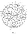
- Figures 1 to 4 are plan views of trays according to the invention with a diameter of 230 mm
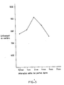
- Figure 5 is a graph illustrating the invention.
- the lapping plate represented in FIG. 1 consists of a matrix 1 made of a mixture of resin and copper, the resin representing 2/3 by weight of the mixture.
- the matrix 1 is continuous and represents the tender parts.
- the hard parts are made up of islands 2 whose faces are flush with the surface of the plate are circular, having a diameter of 25 mm.
- the curve C1 is also shown, which is the trace of a point of an object to be polished on the polishing plate.
- This curve C1 cuts, in the tender matrix, arcs of which more than 50% have a length of between 1 and 5 mm.
- This circle cuts, on the soft matrix, the arcs 3 to 13 whose respective lengths are 8, 3, 6, 12, 2, 17, 10, 7, 8, 6, 2 and 12.
- the islands 22 have substantially the shape of a rectangle whose long sides have recesses.
- the interval between two short sides 23 of a rectangle is 2 mm.
- the interval between the two recessed portions 24 of the long sides of the rectangle is also 2 mm.
- the interval between the long sides immediately adjacent to the short sides 23 is 2 mm.
- the interval in the sections connecting the recessed parts to the rest of the long sides is only 1 mm.
- the hard rectangular islands 32 are scattered in a matrix 33.
- the distance separating two islands, counted along their sides, is 2 mm.
- the hard islands 42 are disseminated in the tender matrix 41, the distance separating two islands is such that the arcs cut out in the tender parts have lengths between 0.5 and 5 mm.
- the removal of materials is 615. This value of the removal of materials is taken as an index base equal to 100.
- the yield is 144.
- Table III gives the results for a plate of the same type as that of FIG. 1, but in which the diameter of the islands is 20 mm. The percentage of islets is 70%. The yield is 141.
- Table IV gives the results for a plate of the same type as that of FIG. 1, but the islands of which have a diameter of 13 mm. The percentage of islets is 72. The yield is 135.
- Tables V to X give the results obtained with plates conforming to FIG. 2, but the intervals between the two short sides of the hard pads and the recessed portions of the long sides of the hard pads are respectively 0.5 mm, 1 mm , 2 mm, 4 mm, 6 mm and 8 mm.
- the hard island percentages are 95, 91, 81, 69, 57 and 51, respectively.
- Returns are 126, 131, 148, 137, 122, 103.
- FIG. 5 the variation in the removal of materials has been plotted as a function of the intervals between the hard parts. It is clearly seen that a maximum of material removal appears for a value close to 2 mm, the range going from 0.5 to 6 mm corresponding to material removals greater than 750. There is a close correlation between the length of the arcs cut in the tender parts and the lengths of the intervals between the hard parts.
Landscapes
- Engineering & Computer Science (AREA)
- Mechanical Engineering (AREA)
- Polishing Bodies And Polishing Tools (AREA)
- Finish Polishing, Edge Sharpening, And Grinding By Specific Grinding Devices (AREA)
- Removal Of Insulation Or Armoring From Wires Or Cables (AREA)
- Mechanical Treatment Of Semiconductor (AREA)
- Grinding And Polishing Of Tertiary Curved Surfaces And Surfaces With Complex Shapes (AREA)
- Prostheses (AREA)
Abstract
Description
- La présente invention concerne des plateaux de polissage ou de rodage, notamment ceux utilisés dans des machines de polissage comprenant un plateau entraîné en rotation autour de son axe, un porte-pièces décentré par rapport au plateau et entraîné en rotation, notamment par frottement, autour de son axe propre et une suspension abrasive interposée entre les pièces à polir et le plateau, les pièces étant appliquées sur le plateau, avec interposition de la suspension, avec une certaine pression.
- Au brevet des Etats-Unis d'Amérique numéro 3.913.279, on décrit un plateau de polissage à la surface plane duquel affleurent des parties tendres sous forme d'îlots disséminés régulièrement dans une partie dure continue. Dans le présent mémoire on entend, par parties dures, des parties plus dures que les parties tendres du plateau. Les parties tendres sont réparties régulièrement sur des cercles concentriques du plateau. On n'attache aucune importance aux longueurs des intervalles entre les parties dures qui, au dessin, et dans le plateau correspondant vendu dans le commerce, sont très grandes.
- Au brevet de la Confédération Helvétique numéro 641.396, on décrit un plateau de polissage dont les parties tendres affectent la forme d'une spirale continue. La largeur de la spirale n'est pas précisée. Elle est de l'ordre de 10 mm dans le produit correspondant vendu dans le commerce et a aussi cette longueur au dessin, en faisant l'hypothèse que le plateau représenté a le diamètre qui est courant dans la technique.
- On a maintenant trouvé, d'une manière inattendue, que les longueurs des intervalles entre des parties dures jouent un rôle déterminant dans le rendement de polissage ou quantité de matière enlevée par unité de temps.
- L'invention vise donc un plateau de polissage dont le rendement est augmenté.
- Le plateau suivant l'invention est caractérisé en ce que plus de la moitié des arcs découpés dans les parties tendres par un cercle imaginaire de rayon égal aux 9/20ème de celui du disque et dont le centre est à une distance de celui du disque égale a la moitié du rayon du disque, ont une longueur comprise entre 0,5 et 8 mm.
- En toute rigueur, la courbe, sur laquelle sont découpés les arcs, à prendre en considération est la trace de la trajectoire d'un point d'une pièce à polir ou à roder sur le plateau. De telles courbes sont représentées aux figures. Mais, par souci de simplification, on peut les assimiler au cercle imaginaire avec une approximation suffisante aux fins de définition de l'invention.
- De préférence 80 % et mieux encore 90 % des arcs ont une longueur comprise entre 0,5 et 5 mm et, mieux encore, entre 1 et 4 mm.
- Il existe une longueur des arcs, très petite au vu de l'art antérieur, qui donne le rendement optimum.
- Si, pour faciliter la fabrication, on souhaite donner aux parties dures des formes identiques, on ne peut satisfaire au critère posé par l'invention que si les parties dures forment des îlots isolés dans une matrice tendre, qui est continue c'est-à-dire d'un seul tenant. Ce mode de réalisation est contraire à celui connu dans l'état de la technique. On constate en outre qu'il permet de donner au plateau une planéité meilleure.
- De préférence, les îlots sont rectangulaires, le rapport de la longueur des grands côtés à celle des petits côtés étant compris entre 1,5 et 3. On améliore les résultats par des renfoncements ménagés dans les grands côtés.
- L'art antérieur considérait que le rendement optimum était atteint pour 70 % de parties dures et 30 % de parties tendres. Mais quand on respecte le critère de longueur des arcs, des essais montrent que le rendement est le meilleur quand les parties dures représentent de 85 à 95 % de la somme des parties dures et des parties tendres.
- Les parties dures du plateau peuvent être des poudres en fonte, en fer, en cuivre, en acier inoxydable, en chrome, en carbure, en oxydes, notamment en oxyde d'alumine, de préférence mélangées à des résines telles que des résines polyester, des résines acryliques et des résines phénolformaldéhyde. Les parties tendres peuvent être des poudres métalliques, par exemple de cuivre, de bronze, d'alliages de cuivre et de plomb, de laiton, d'alliages de cuivre et d'aluminium, d'aluminium, de plomb, d'antimoine, d'étain et de zinc, de préférence également mélangées à des résines, notamment des résines de polyester, acryliques et phénolformaldéhydes. Dans ces mélanges de résines et de poudres métalliques, la résine représente avantageusement de 20 à 40 % du poids total.
- Les abrasifs utilisés sont des produits ayant sur l'échelle de Mosh une dureté d'au moins 9 et, sur l'échelle de Knoop, une dureté supérieure à 1200. Ces abrasifs, qui sont plus durs que les parties dures du plateau, sont notamment du corindon, de l'alumine fondue, du carbure de silicium, du carbure de bore et du diamant, ce dernier étant préféré. L'abrasif se présente sous la forme d'une suspension des produits abrasifs mentionnés ci-dessus, dans un liant, la granulométrie des abrasifs étant comprise entre 1 micron et 200 microns et, de préférence, entre 10 microns et 40 microns et le pourcentage des abrasifs dans le liant étant compris entre 0,2 et 5 % en poids et le pourcentage des abrasifs dans le liant étant compris entre 0,2 et 5 % en poids et, de préférence, entre 1 et 3 % en poids. Le liant peut être constitué d'un mélange d'eau et de glycols, les glycols représentant de 10 à 60 % du poids total du liant et, de préférence, de 20 à 50 % de ce poids. Le liant peut être aussi constitué d'un mélange d'eau et de kérosène, ce dernier représentant de 40 à 60 % du poids total du liant.
- Au dessin annexé, donné uniquement à titre d'exemple, les figures 1 à 4 sont des vues en plan de plateaux suivant l'invention d'un diamètre de 230 mm, et la figure 5 est un graphique illustrant l'invention.
- Le plateau de rodage représenté à la figure 1 est constitué d'une matrice 1 en un mélange de résine et de cuivre, la résine représentant les 2/3 en poids du mélange. La matrice 1 est continue et représente les parties tendres. Les parties dures sont constituées d'îlots 2 dont les faces affleurant à la surface du plateau sont circulaires, en ayant un diamètre de 25 mm.
- On a représenté également la courbe C1 qui est la trace d'un point d'un objet à polir sur le plateau de polissage. Cette courbe C1 découpe, dans la matrice tendre, des arcs dont plus de 50 % ont une longueur comprise entre 1 et 5 mm. On peut assimiler aussi cette courbe au cercle C imaginaire de rayon égal à la moitié de celui du disque et dont le centre est à une distance de celui du disque égale à la moitié du rayon du disque. Ce cercle découpe, sur la matrice tendre, les arcs 3 à 13 dont les longueurs respectives sont 8, 3, 6, 12, 2, 17, 10, 7, 8, 6, 2 et 12.
- A la figure 2, les îlots 22 ont sensiblement la forme d'un rectangle dont les grands côtés ont des renfoncements. L'intervalle entre deux petits côtés 23 d'un rectangle est de 2 mm. L'intervalle entre les deux parties renfoncées 24 des grands côtés du rectangle est également de 2 mm. L'intervalle entre les segments de grands côtés immédiatement adjacents aux petits côtés 23 est de 2 mm. L'intervalle dans les tronçons reliant les parties renfoncées au reste des grands côtés n'est que de 1 mm.
- A la figure 3, les îlots 32 rectangulaires durs sont disséminés dans une matrice 33. La distance séparant deux îlots, décomptée le long de leurs côtés, est de 2 mm.
- A la figure 4, les îlots durs 42 sont disséminés dans la matrice tendre 41, la distance séparant deux îlots est telle aussi que les arcs découpés dans les parties tendres ont des longueurs comprises entre 0,5 et 5 mm.
- Pour déterminer le rendement des plateaux, on rode six pièces cylindriques d'un diamètre de 20 mm en appliquant une pression de 265 g/cm² sur une machine de rodage, la vitesse de rotation de la machine étant de 150 tours/minute et la vitesse de rotation du porte-pièces de 175 tours/minute ce qui correspond à une vitesse linéaire des pièces de 0,8 m/s. On effectue six cycles d'une durée de 5 minutes chacun. On utilise comme abrasif du liquide diamant de marque MM 381 fourni par la demanderesse. Toutes les 5 minutes, on mesure l'enlèvement de matières en micron sur les six pièces. On fait également le total de l'enlèvement de matière sur toutes les pièces et sur tous les cycles.
- Pour un plateau de l'art antérieur de la demanderesse, tel que décrit au brevet des Etats-Unis d'Amérique mentionné ci-dessus, l'enlèvement de matières est de 615. On prend cette valeur de l'enlèvement de matières comme indice de base égal à 100.
- Les résultats obtenus sont rapportés au tableau I. Au tableau II, on a remplacé les îlots tendres du plateau de l'art antérieur par des îlots durs de manière que ces îlots durs représentent 71 % de la surface du plateau, alors que les îlots tendres représentaient 70 % du plateau suivant l'art antérieur. Les résultats obtenus sont consignés au tableau II.
TABLEAU I No E.M. E.M. E.M. E.M. E.M. 1 19 20 20 20 24 2 16 20 20 16 22 3 16 21 17 19 21 4 19 22 19 21 22 5 20 20 25 21 23 6 22 20 22 24 24 Total EM 112 123 123 121 136 Total EM/5 cycles Moy. EM 3,73 4,1 4,1 4,03 4,53 615 Ecart 6 6 8 8 3 TABLEAU II No E.M. E.M. E.M. E.M. E.M. 1 31 26 31 31 29 2 27 27 28 24 26 3 27 27 28 26 23 4 33 30 26 28 29 5 36 27 32 33 35 6 34 28 36 26 38 Total EM/5 cycles Total EM 193 167 178 168 180 886 Moy. EM 6,43 5,56 5,93 5,6 6 Ecart 9 4 11 7 15 - Le rendement est de 144.
- Le tableau III donne les résultats pour un plateau du même type que celui de la figure 1, mais dans lequel le diamètre des îlots est de 20 mm. Le pourcentage des îlots est de 70 %. Le rendement est de 141. Le tableau IV donne les résultats pour un plateau de même type que celui de la figure 1, mais dont les îlots ont un diamètre de 13 mm. Le pourcentage des îlots est de 72. Le rendement est de 135.
- Les tableaux V à X donnent les résultats obtenus avec des plateaux conformes à la figure 2, mais dont les intervalles entre les deux petits côtés des plots durs et les parties renfoncées des longs côtés des plots durs sont respectivement de 0,5 mm, 1 mm, 2 mm, 4 mm, 6 mm et 8 mm. Les pourcentages d'îlots durs sont 95, 91, 81, 69, 57 et 51, respectivement. Les rendements sont de 126, 131, 148, 137, 122, 103. On a tracé, à la figure 5, la variation de l'enlèvement de matières en fonction des intervalles entre les parties dures. On voit nettement qu'il apparaît un maximum d'enlèvement de matières pour une valeur voisine de 2 mm, la plage allant de 0,5 a 6 mm correspondant à des enlèvements de matières supérieurs à 750. Il y a une corrélation étroite entre la longueur des arcs découpés dans les parties tendres et les longueurs des intervalles entre les parties dures.
- On constate, en outre, sur tous ces tableaux, que la différence de cote (écart) entre les pièces pour les différentes passes est d'autant plus faible que le rendement est meilleur.
- Au tableau XI, on donne les résultats obtenus avec un plateau suivant la figure 3 et, au tableau XII, avec un plateau suivant la figure 4. Les rendements sont de 147 et 140.
TABLEAU III No E.M. E.M. E.M. E.M. E.M. 1 27 23 34 32 29 2 24 27 29 30 24 3 22 29 30 24 22 4 28 27 28 26 25 5 30 33 32 32 31 6 32 35 32 36 32 Total EM/5 cycles Total EM 163 174 185 180 163 865 Moy. EM 5,43 5,8 6,16 6 5,43 Ecart 10 8 6 8 10 TABLEAU IV No E.M. E.M. E.M. E.M. E.M. 1 22 26 30 28 31 2 20 22 28 28 29 3 21 23 25 27 30 4 23 23 35 26 32 5 31 24 34 35 29 6 24 28 34 36 29 Total EM/5 cycles Total EM 141 146 186 180 180 833 Moy. EM 4,7 4,86 8,2 6 6 Ecart 11 6 10 10 3 TABLEAU V No E.M. E.M. E.M. E.M. E.M. 1 22 25 27 29 23 2 23 27 23 33 24 3 19 27 30 29 24 4 21 24 31 31 24 5 19 26 29 29 23 6 22 25 27 28 23 Total EM/5 cycles Total EM 126 154 177 179 139 775 Moy. EM 4,2 5,13 5,9 5,96 4,6 Ecart 4 3 8 5 1 TABLEAU VI No E.M. E.M. E.M. E.M. E.M. 1 24 27 27 27 27 2 25 26 28 31 25 3 24 28 29 30 27 4 29 26 28 30 27 5 24 26 29 27 26 6 24 24 28 28 28 Total EM/5 cycles Total EM 150 157 169 173 157 806 Moy. EM 5 5,23 5,63 5,76 5,2 Ecart 5 5 2 4 3 TABLEAU VII No E.M. E.M. E.M. E.M. E.M. 1 28 28 32 31 30 2 30 30 32 32 31 3 31 31 32 33 31 4 29 30 32 32 28 5 28 29 32 31 29 6 29 28 31 30 29 Total EM/5 cycles Total EM 175 176 191 189 178 909 Ecart 3 3 1 3 3 TABLEAU VIII No E.M. E.M. E.M. E.M. E.M. 1 26 29 27 22 26 2 26 30 27 30 30 3 28 29 29 30 28 4 29 27 30 30 29 5 27 28 29 27 28 6 25 28 26 29 27 Total EM/5 cycles Total EM 161 171 168 175 168 843 Moy. EM 5,36 5,7 5,6 5,83 5,6 Ecart 4 4 4 8 4 TABLEAU IX No E.M. E.M. E.M. E.M. E.M. 1 23 26 24 24 24 2 23 27 25 25 25 3 25 27 26 26 27 4 26 26 25 24 29 5 24 26 24 25 24 6 23 26 24 25 24 Total EM/5 cycles Total EM 144 158 148 149 153 752 Ecart 3 3 2 2 5 TABLEAU X No E.M. E.M. E.M. E.M. E.M. 1 20 21 22 21 21 2 22 22 21 20 22 3 22 21 22 21 23 4 19 22 21 20 23 5 21 21 20 21 20 6 19 22 19 21 22 Total EM/5 cycles Total EM 123 129 125 124 131 632 Ecart 3 1 3 1 3 TABLEAU XI No E.M. E.M. E.M. E.M. E.M. 1 26 32 30 31 31 2 31 29 30 32 31 3 30 29 31 33 31 4 32 27 33 33 29 5 29 28 31 31 28 6 27 31 28 30 29 Total EM/5 cycles Total EM 175 176 183 190 179 903 Ecart 6 5 5 3 3 TABLEAU XII No E.M. E.M. E.M. E.M. E.M. 1 27 28 28 30 30 2 28 30 27 33 29 3 28 29 30 33 30 4 28 29 26 33 29 5 29 26 30 30 29 6 28 26 28 30 29 Total EM/5 cycles Total EM 168 168 169 189 167 861 Ecart 2 4 4 3 1
Claims (8)
Priority Applications (1)
| Application Number | Priority Date | Filing Date | Title |
|---|---|---|---|
| AT89402889T ATE78205T1 (de) | 1988-11-22 | 1989-10-19 | Polierscheibe. |
Applications Claiming Priority (2)
| Application Number | Priority Date | Filing Date | Title |
|---|---|---|---|
| FR8813919A FR2639278B1 (fr) | 1988-11-22 | 1988-11-22 | Plateau de polissage |
| FR8813919 | 1988-11-22 |
Publications (2)
| Publication Number | Publication Date |
|---|---|
| EP0370843A1 true EP0370843A1 (fr) | 1990-05-30 |
| EP0370843B1 EP0370843B1 (fr) | 1992-07-15 |
Family
ID=9371247
Family Applications (1)
| Application Number | Title | Priority Date | Filing Date |
|---|---|---|---|
| EP89402889A Expired - Lifetime EP0370843B1 (fr) | 1988-11-22 | 1989-10-19 | Plateau de polissage |
Country Status (13)
| Country | Link |
|---|---|
| US (1) | US5022191A (fr) |
| EP (1) | EP0370843B1 (fr) |
| JP (1) | JPH02262957A (fr) |
| KR (1) | KR0150779B1 (fr) |
| AT (1) | ATE78205T1 (fr) |
| CA (1) | CA2003381C (fr) |
| DE (1) | DE68902131T2 (fr) |
| DK (1) | DK169061B1 (fr) |
| ES (1) | ES2033542T3 (fr) |
| FR (1) | FR2639278B1 (fr) |
| GR (1) | GR3005624T3 (fr) |
| HU (1) | HUT53001A (fr) |
| IE (1) | IE62270B1 (fr) |
Cited By (2)
| Publication number | Priority date | Publication date | Assignee | Title |
|---|---|---|---|---|
| FR2786118A1 (fr) * | 1998-11-19 | 2000-05-26 | Lam Plan Sa | Dispositif de rodage ou polissage |
| CN108188945A (zh) * | 2018-03-12 | 2018-06-22 | 桂林创源金刚石有限公司 | 一种薄片齿拼合式金刚石砂轮及制作方法 |
Families Citing this family (18)
| Publication number | Priority date | Publication date | Assignee | Title |
|---|---|---|---|---|
| JP2985490B2 (ja) * | 1992-02-28 | 1999-11-29 | 信越半導体株式会社 | 研磨機の除熱方法 |
| FR2740716B1 (fr) * | 1995-11-08 | 1998-01-02 | Lam Plan Sa | Rodoir et son procede de fabrication |
| TW349896B (en) * | 1996-05-02 | 1999-01-11 | Applied Materials Inc | Apparatus and chemical mechanical polishing system for polishing a substrate |
| US6019666A (en) * | 1997-05-09 | 2000-02-01 | Rodel Holdings Inc. | Mosaic polishing pads and methods relating thereto |
| JP3056714B2 (ja) * | 1997-10-06 | 2000-06-26 | 松下電子工業株式会社 | 半導体基板の研磨方法 |
| US6634929B1 (en) * | 1999-04-23 | 2003-10-21 | 3M Innovative Properties Company | Method for grinding glass |
| US6616513B1 (en) * | 2000-04-07 | 2003-09-09 | Applied Materials, Inc. | Grid relief in CMP polishing pad to accurately measure pad wear, pad profile and pad wear profile |
| USD502378S1 (en) * | 2002-11-18 | 2005-03-01 | Ehwa Diamond Industrial Co., Ltd. | Pad for grinding stone |
| USD538312S1 (en) * | 2005-09-16 | 2007-03-13 | 3M Innovative Properties Company | Abrasive article with holes |
| USD538313S1 (en) | 2005-09-16 | 2007-03-13 | 3M Innovative Properties Company | Abrasive article with holes |
| USD536714S1 (en) | 2005-09-16 | 2007-02-13 | 3M Innovative Properties Company | Abrasive article with holes |
| USD541317S1 (en) | 2006-02-01 | 2007-04-24 | 3M Innovative Properties Company | Abrasive article with holes |
| USD533200S1 (en) * | 2006-02-01 | 2006-12-05 | 3M Innovative Properties Company | Abrasive article with holes |
| USD532800S1 (en) * | 2006-02-01 | 2006-11-28 | 3M Innovative Properties Company | Abrasive article with holes |
| USD543562S1 (en) | 2006-02-01 | 2007-05-29 | 3M Innovative Properties Company | Abrasive article with holes |
| USD645065S1 (en) | 2008-05-22 | 2011-09-13 | 3M Innovative Properties Company | Abrasive article with holes |
| WO2017033280A1 (fr) * | 2015-08-25 | 2017-03-02 | 株式会社クリスタル光学 | Outil de meulage et son procédé de fabrication |
| USD988377S1 (en) * | 2020-02-24 | 2023-06-06 | 3M Innovative Properties Company | Abrasive article |
Citations (3)
| Publication number | Priority date | Publication date | Assignee | Title |
|---|---|---|---|---|
| FR1104941A (fr) * | 1954-05-19 | 1955-11-25 | Perfectionnement aux meules notamment aux meules diamant | |
| US3921342A (en) * | 1973-12-17 | 1975-11-25 | Spitfire Tool & Machine Co Inc | Lap plate |
| US4037367A (en) * | 1975-12-22 | 1977-07-26 | Kruse James A | Grinding tool |
Family Cites Families (8)
| Publication number | Priority date | Publication date | Assignee | Title |
|---|---|---|---|---|
| US342943A (en) * | 1886-06-01 | Process of and apparatus for making felt boots | ||
| US1622942A (en) * | 1923-01-17 | 1927-03-29 | Elroy A Chase | Buffing wheel |
| US1926321A (en) * | 1930-10-10 | 1933-09-12 | Turek Johann | Grinding wheel |
| FR2203301A5 (fr) * | 1972-10-18 | 1974-05-10 | Lam Plan Sa | |
| USRE27962E (en) * | 1973-03-05 | 1974-04-02 | Abrasive disc | |
| JPS6013789B2 (ja) * | 1975-07-01 | 1985-04-09 | イプレツツ エス.エイ. | 複合板状つや出し工具 |
| JPS5894965A (ja) * | 1981-11-30 | 1983-06-06 | Yoshiaki Hagiuda | 複合ラツプ工具 |
| US4581853A (en) * | 1982-02-01 | 1986-04-15 | Marcus Ralph S | Apparatus for internal finishing of metal parts |
-
1988
- 1988-11-22 FR FR8813919A patent/FR2639278B1/fr not_active Expired - Lifetime
-
1989
- 1989-10-19 DE DE8989402889T patent/DE68902131T2/de not_active Expired - Lifetime
- 1989-10-19 AT AT89402889T patent/ATE78205T1/de not_active IP Right Cessation
- 1989-10-19 EP EP89402889A patent/EP0370843B1/fr not_active Expired - Lifetime
- 1989-10-19 ES ES198989402889T patent/ES2033542T3/es not_active Expired - Lifetime
- 1989-11-08 HU HU895835A patent/HUT53001A/hu unknown
- 1989-11-13 US US07/434,846 patent/US5022191A/en not_active Expired - Lifetime
- 1989-11-20 JP JP1299903A patent/JPH02262957A/ja active Pending
- 1989-11-20 CA CA002003381A patent/CA2003381C/fr not_active Expired - Fee Related
- 1989-11-21 KR KR1019890016913A patent/KR0150779B1/ko not_active Expired - Fee Related
- 1989-11-21 DK DK584189A patent/DK169061B1/da not_active IP Right Cessation
- 1989-11-21 IE IE372889A patent/IE62270B1/en not_active IP Right Cessation
-
1992
- 1992-09-07 GR GR920401951T patent/GR3005624T3/el unknown
Patent Citations (3)
| Publication number | Priority date | Publication date | Assignee | Title |
|---|---|---|---|---|
| FR1104941A (fr) * | 1954-05-19 | 1955-11-25 | Perfectionnement aux meules notamment aux meules diamant | |
| US3921342A (en) * | 1973-12-17 | 1975-11-25 | Spitfire Tool & Machine Co Inc | Lap plate |
| US4037367A (en) * | 1975-12-22 | 1977-07-26 | Kruse James A | Grinding tool |
Non-Patent Citations (1)
| Title |
|---|
| PATENT ABSTRACTS OF JAPAN, vol. 7, no. 197 (M-239)[1342], 27 août 1983; & JP-A-58 94 965 (YOSHIAKI HAGIUDA) 06-06-1983 * |
Cited By (5)
| Publication number | Priority date | Publication date | Assignee | Title |
|---|---|---|---|---|
| FR2786118A1 (fr) * | 1998-11-19 | 2000-05-26 | Lam Plan Sa | Dispositif de rodage ou polissage |
| WO2000030806A1 (fr) * | 1998-11-19 | 2000-06-02 | Lam-Plan | Dispositif de rodage ou polissage |
| US6837780B1 (en) | 1998-11-19 | 2005-01-04 | Lam-Plan S.A. | Lapping and polishing device |
| CN108188945A (zh) * | 2018-03-12 | 2018-06-22 | 桂林创源金刚石有限公司 | 一种薄片齿拼合式金刚石砂轮及制作方法 |
| CN108188945B (zh) * | 2018-03-12 | 2023-08-01 | 桂林创源金刚石有限公司 | 一种薄片齿拼合式金刚石砂轮及制作方法 |
Also Published As
| Publication number | Publication date |
|---|---|
| US5022191A (en) | 1991-06-11 |
| DK584189D0 (da) | 1989-11-21 |
| CA2003381C (fr) | 1999-07-13 |
| ES2033542T3 (es) | 1993-03-16 |
| HU895835D0 (en) | 1990-01-28 |
| DE68902131D1 (de) | 1992-08-20 |
| EP0370843B1 (fr) | 1992-07-15 |
| HUT53001A (en) | 1990-09-28 |
| DK584189A (da) | 1990-05-23 |
| FR2639278B1 (fr) | 1991-01-11 |
| IE62270B1 (en) | 1995-01-11 |
| KR900007550A (ko) | 1990-06-01 |
| FR2639278A1 (fr) | 1990-05-25 |
| DK169061B1 (da) | 1994-08-08 |
| KR0150779B1 (ko) | 1998-10-15 |
| CA2003381A1 (fr) | 1990-05-22 |
| JPH02262957A (ja) | 1990-10-25 |
| ATE78205T1 (de) | 1992-08-15 |
| IE893728L (en) | 1990-05-22 |
| GR3005624T3 (fr) | 1993-06-07 |
| DE68902131T2 (de) | 1993-01-14 |
Similar Documents
| Publication | Publication Date | Title |
|---|---|---|
| EP0370843B1 (fr) | Plateau de polissage | |
| US6113476A (en) | Versatile ultrahone sharpener | |
| KR100713039B1 (ko) | 질화물 반도체 기판의 엣지 가공 방법 | |
| US6110030A (en) | Ultra fine groove chip and ultra fine groove tool | |
| JP5701211B2 (ja) | 研磨剤を含浸する電鋳製薄型カッティングソー及びコアドリル | |
| US20220048161A1 (en) | Metal bond grindstone for hard and brittle material | |
| US3919811A (en) | Grinding wheel for forming a facet on the periphery of an eyeglass lens | |
| KR102856873B1 (ko) | 타깃재의 연마 방법, 타깃재의 제조 방법 및 리사이클 주괴의 제조 방법 | |
| US11819979B2 (en) | Abrasive tool | |
| JPH10286755A (ja) | 砥粒固定型研磨定盤のコンディショニング方法 | |
| JP2971764B2 (ja) | 砥粒固定型研磨定盤 | |
| EP1131186B1 (fr) | Dispositif de rodage ou polissage | |
| JP2000326236A (ja) | 縦軸研削用砥石 | |
| JP2000301468A (ja) | 研削用砥石及び縦軸研削用砥石 | |
| FR2554376A1 (fr) | Procede de faconnage de pieces en materiaux cassants et application de ce procede | |
| JPH0632905B2 (ja) | ▲iii▼―v族化合物半導体ウエハ薄層化処理方法 | |
| JPH01264771A (ja) | といし車の形直しおよび目直し用工具並びにそれの使用方法 | |
| Levinson | Process optimization of dicing microelectronic substrates | |
| US3290835A (en) | Segmental abrasive wheel | |
| JP2000301467A (ja) | 縦軸研削用砥石 | |
| JPH06226640A (ja) | 平面研磨装置及び該装置に使用する扇形固形砥石片 | |
| JPH0760648A (ja) | 精密研削切断砥石 | |
| BE1001782A4 (fr) | Outil abrasif pour le tronconnage-flettage combines d'articles de verrerie ou de cristallerie. | |
| JP2000326237A (ja) | 縦軸研削用砥石 | |
| GB2234924A (en) | Ring-type abrasive cut-off wheel |
Legal Events
| Date | Code | Title | Description |
|---|---|---|---|
| PUAI | Public reference made under article 153(3) epc to a published international application that has entered the european phase |
Free format text: ORIGINAL CODE: 0009012 |
|
| AK | Designated contracting states |
Kind code of ref document: A1 Designated state(s): AT BE CH DE ES FR GB GR IT LI LU NL SE |
|
| 17P | Request for examination filed |
Effective date: 19900711 |
|
| 17Q | First examination report despatched |
Effective date: 19911210 |
|
| ITF | It: translation for a ep patent filed | ||
| GRAA | (expected) grant |
Free format text: ORIGINAL CODE: 0009210 |
|
| AK | Designated contracting states |
Kind code of ref document: B1 Designated state(s): AT BE CH DE ES FR GB GR IT LI LU NL SE |
|
| REF | Corresponds to: |
Ref document number: 78205 Country of ref document: AT Date of ref document: 19920815 Kind code of ref document: T |
|
| GBT | Gb: translation of ep patent filed (gb section 77(6)(a)/1977) | ||
| REF | Corresponds to: |
Ref document number: 68902131 Country of ref document: DE Date of ref document: 19920820 |
|
| REG | Reference to a national code |
Ref country code: ES Ref legal event code: FG2A Ref document number: 2033542 Country of ref document: ES Kind code of ref document: T3 |
|
| REG | Reference to a national code |
Ref country code: GR Ref legal event code: FG4A Free format text: 3005624 |
|
| PLBE | No opposition filed within time limit |
Free format text: ORIGINAL CODE: 0009261 |
|
| STAA | Information on the status of an ep patent application or granted ep patent |
Free format text: STATUS: NO OPPOSITION FILED WITHIN TIME LIMIT |
|
| 26N | No opposition filed | ||
| EPTA | Lu: last paid annual fee | ||
| EAL | Se: european patent in force in sweden |
Ref document number: 89402889.3 |
|
| PGFP | Annual fee paid to national office [announced via postgrant information from national office to epo] |
Ref country code: GR Payment date: 20001002 Year of fee payment: 12 |
|
| PGFP | Annual fee paid to national office [announced via postgrant information from national office to epo] |
Ref country code: ES Payment date: 20001005 Year of fee payment: 12 |
|
| PGFP | Annual fee paid to national office [announced via postgrant information from national office to epo] |
Ref country code: LU Payment date: 20001006 Year of fee payment: 12 Ref country code: SE Payment date: 20001006 Year of fee payment: 12 |
|
| PGFP | Annual fee paid to national office [announced via postgrant information from national office to epo] |
Ref country code: BE Payment date: 20001023 Year of fee payment: 12 |
|
| PGFP | Annual fee paid to national office [announced via postgrant information from national office to epo] |
Ref country code: AT Payment date: 20001024 Year of fee payment: 12 |
|
| PG25 | Lapsed in a contracting state [announced via postgrant information from national office to epo] |
Ref country code: AT Free format text: LAPSE BECAUSE OF NON-PAYMENT OF DUE FEES Effective date: 20011019 Ref country code: LU Free format text: LAPSE BECAUSE OF NON-PAYMENT OF DUE FEES Effective date: 20011019 |
|
| PG25 | Lapsed in a contracting state [announced via postgrant information from national office to epo] |
Ref country code: ES Free format text: LAPSE BECAUSE OF NON-PAYMENT OF DUE FEES Effective date: 20011020 Ref country code: SE Free format text: LAPSE BECAUSE OF NON-PAYMENT OF DUE FEES Effective date: 20011020 |
|
| PG25 | Lapsed in a contracting state [announced via postgrant information from national office to epo] |
Ref country code: BE Free format text: LAPSE BECAUSE OF NON-PAYMENT OF DUE FEES Effective date: 20011031 Ref country code: GR Free format text: LAPSE BECAUSE OF NON-PAYMENT OF DUE FEES Effective date: 20011031 |
|
| REG | Reference to a national code |
Ref country code: GB Ref legal event code: IF02 |
|
| BERE | Be: lapsed |
Owner name: S.A. LAM-PLAN Effective date: 20011031 |
|
| EUG | Se: european patent has lapsed |
Ref document number: 89402889.3 |
|
| PGFP | Annual fee paid to national office [announced via postgrant information from national office to epo] |
Ref country code: NL Payment date: 20021031 Year of fee payment: 14 |
|
| REG | Reference to a national code |
Ref country code: ES Ref legal event code: FD2A Effective date: 20021113 |
|
| PG25 | Lapsed in a contracting state [announced via postgrant information from national office to epo] |
Ref country code: NL Free format text: LAPSE BECAUSE OF NON-PAYMENT OF DUE FEES Effective date: 20040501 |
|
| NLV4 | Nl: lapsed or anulled due to non-payment of the annual fee |
Effective date: 20040501 |
|
| PG25 | Lapsed in a contracting state [announced via postgrant information from national office to epo] |
Ref country code: IT Free format text: LAPSE BECAUSE OF NON-PAYMENT OF DUE FEES;WARNING: LAPSES OF ITALIAN PATENTS WITH EFFECTIVE DATE BEFORE 2007 MAY HAVE OCCURRED AT ANY TIME BEFORE 2007. THE CORRECT EFFECTIVE DATE MAY BE DIFFERENT FROM THE ONE RECORDED. Effective date: 20051019 |
|
| PGFP | Annual fee paid to national office [announced via postgrant information from national office to epo] |
Ref country code: CH Payment date: 20081031 Year of fee payment: 20 Ref country code: DE Payment date: 20081030 Year of fee payment: 20 |
|
| PGFP | Annual fee paid to national office [announced via postgrant information from national office to epo] |
Ref country code: FR Payment date: 20081028 Year of fee payment: 20 |
|
| PGFP | Annual fee paid to national office [announced via postgrant information from national office to epo] |
Ref country code: GB Payment date: 20081031 Year of fee payment: 20 |
|
| REG | Reference to a national code |
Ref country code: CH Ref legal event code: PL |
|
| REG | Reference to a national code |
Ref country code: GB Ref legal event code: PE20 Expiry date: 20091018 |
|
| PG25 | Lapsed in a contracting state [announced via postgrant information from national office to epo] |
Ref country code: GB Free format text: LAPSE BECAUSE OF EXPIRATION OF PROTECTION Effective date: 20091018 |