EP0370942A2 - Vorrichtung zur in Echtzeit digitalen additiven Synthese - Google Patents
Vorrichtung zur in Echtzeit digitalen additiven Synthese Download PDFInfo
- Publication number
- EP0370942A2 EP0370942A2 EP89630205A EP89630205A EP0370942A2 EP 0370942 A2 EP0370942 A2 EP 0370942A2 EP 89630205 A EP89630205 A EP 89630205A EP 89630205 A EP89630205 A EP 89630205A EP 0370942 A2 EP0370942 A2 EP 0370942A2
- Authority
- EP
- European Patent Office
- Prior art keywords
- partial
- pitch
- timbre
- adder
- musical instrument
- Prior art date
- Legal status (The legal status is an assumption and is not a legal conclusion. Google has not performed a legal analysis and makes no representation as to the accuracy of the status listed.)
- Withdrawn
Links
- 239000000654 additive Substances 0.000 title 1
- 230000000996 additive effect Effects 0.000 title 1
- 230000036961 partial effect Effects 0.000 claims abstract description 110
- 239000011295 pitch Substances 0.000 claims description 89
- 230000015654 memory Effects 0.000 claims description 19
- 230000006870 function Effects 0.000 claims description 7
- 230000004044 response Effects 0.000 claims description 5
- 230000000717 retained effect Effects 0.000 claims 1
- 238000010276 construction Methods 0.000 description 9
- 239000002131 composite material Substances 0.000 description 3
- 238000010586 diagram Methods 0.000 description 3
- 238000007792 addition Methods 0.000 description 2
- 230000003416 augmentation Effects 0.000 description 2
- 230000003190 augmentative effect Effects 0.000 description 2
- 230000008901 benefit Effects 0.000 description 2
- 230000008859 change Effects 0.000 description 2
- 230000007547 defect Effects 0.000 description 2
- 230000000694 effects Effects 0.000 description 2
- 239000011159 matrix material Substances 0.000 description 2
- 230000007246 mechanism Effects 0.000 description 2
- 230000000135 prohibitive effect Effects 0.000 description 2
- 230000002194 synthesizing effect Effects 0.000 description 2
- 230000015572 biosynthetic process Effects 0.000 description 1
- 239000013078 crystal Substances 0.000 description 1
- 238000004519 manufacturing process Methods 0.000 description 1
- 238000000034 method Methods 0.000 description 1
- 230000004048 modification Effects 0.000 description 1
- 238000012986 modification Methods 0.000 description 1
- 230000010076 replication Effects 0.000 description 1
- 238000005070 sampling Methods 0.000 description 1
- 230000003068 static effect Effects 0.000 description 1
- 238000003786 synthesis reaction Methods 0.000 description 1
Images

Classifications
-
- G—PHYSICS
- G10—MUSICAL INSTRUMENTS; ACOUSTICS
- G10H—ELECTROPHONIC MUSICAL INSTRUMENTS; INSTRUMENTS IN WHICH THE TONES ARE GENERATED BY ELECTROMECHANICAL MEANS OR ELECTRONIC GENERATORS, OR IN WHICH THE TONES ARE SYNTHESISED FROM A DATA STORE
- G10H7/00—Instruments in which the tones are synthesised from a data store, e.g. computer organs
- G10H7/08—Instruments in which the tones are synthesised from a data store, e.g. computer organs by calculating functions or polynomial approximations to evaluate amplitudes at successive sample points of a tone waveform
-
- G—PHYSICS
- G10—MUSICAL INSTRUMENTS; ACOUSTICS
- G10H—ELECTROPHONIC MUSICAL INSTRUMENTS; INSTRUMENTS IN WHICH THE TONES ARE GENERATED BY ELECTROMECHANICAL MEANS OR ELECTRONIC GENERATORS, OR IN WHICH THE TONES ARE SYNTHESISED FROM A DATA STORE
- G10H5/00—Instruments in which the tones are generated by means of electronic generators
- G10H5/005—Voice controlled instruments
Definitions
- This invention relates to electronic musical instruments and more particularly to such instruments of the digital synthesizer type in which the output waveform is computed from a plurality of component waveforms.
- VOICE a complex waveform consisting of pitched and unpitched components and including its amplitude envelope.
- TIMBRE the portion of a voice consisting of pitched components only. Somtimes***** this term is used to include unpitched components also. In no case does it include the amplitude envelope.
- PITCH a term used synonymously with frequency. FUNDAMENTAL the pitched component with the lowest pitch. Note that the amplitude of a fundamental can be zero and still be valid. If sufficient overtones exist to establish the fundamental, it will be apparent even if it does not exist.
- OVERTONE a pitched component of higher frequency than the fundamental. Harmonics are a subset of overtones. The fundamental is not an overtone.
- HARMONIC a pitched component of higher frequency than the fundamental which also has an integral relationship in pitch with the fundamental. Since it is the reference by which harmonics are defined, the fundamental is not strictly a harmonic; yet, when included with harmonics as a set the fundamental is often referred to as the first harmonic. PARTIAL any pitched or unpitched component part of a voice.
- FRACTIONAL a new term connoting an overtone with a simple fractional relationship with the fundamental such as 1/2, 1/3, 1/4, etc.
- Timbres or musical sounds produced in this wave typically have complex waveforms which are fixed in shape from cycle to cycle.
- An advantage resulting from this characteristic is that a single cycle of the waveform may be placed in a memory and played back by traversing the memory at a desired fundamental pitch rate.
- An electronic musical instrument of this type is disclosed, for example, in U.S. patent 4,601,229 to Deutsch.
- pitched complex waveforms with detuned overtones are not uniform in shape from cycle to cycle. Consequently, they may not be placed in a memory for traversing playback unless a very large memory, capable of containing several seconds of music, is used. Such memories would be prohibitive in size, especially if a multiplicity of voices are to be contained for immediate playback. Therefore, a voice with detuned overtones must be generated in real time.
- Another object of this invention is to provide a musical instrument which will produce a voice overtone structure in which each overtone is individually controllable in both pitch and amplitude.
- Still another object of this invention is to provide a musical instrument which contains, at all times, a multiplicity of voice overtone structures, under executive control, such that instantaneous voice selection may be made in response to time, envelope waveform or musician demands.
- Yet another object of this invention is to provide a hardware structure with a flexibility which allows individual assignment of each computation time period to any voice overtone component desired, including replication of any such component; such flexibility allowing the omission of any component with a zero amplitude coefficient.
- Still another object of this invention is to provide a unique method of overtone production which eliminates, at the least, one multiplication now in state of the art mechanisms and provides a design concept more in harmony with the human concept of voice design.
- an electronic musical instrument of the present invention includes an input interface for accepting input signals from a musician, which input signals specify musical parameters including the fundamental pitch and the timbre desired by the musician.
- Timbre storing circuitry stores data representing a plurality of selectable timbres.
- the timbre storing circuitry includes relative partial pitch storing circuitry for storing a plurality of sets of relative partial pitch data, each set of data representing the relative pitches for a plurality of partials defined for that set.
- the timbre storing circuitry also includes partial amplitude storing circuitry for storing a plurality of sets of partial amplitude data, each set representing the maximum amplitudes for the individual partials of any one of the sets of partials.
- the instrument also includes waveform determining circuitry for determining sequential values of the musical waveform in real time from the timbre data, from the timbre selected by the musician, and from the pitch selected by the musician.
- the sequential values are spaced apart by a predetermined time interval.
- the waveform determining circuitry includes a first adder for additively determining the phase of each partial of the selected timbre, which first adder is responsive to the relative partial pitch storing circuitry to determine the phase of that partial.
- a second adder sums the magnitudes of all the partials for the selected timbre at each predetermined time interval to generate the magnitude of the musical waveform at that instant.
- This model defines a fixed timbre waveform composed of harmonics which are integral multiples of the fundamental, which is only a limited subset of the timbres actually required.
- the pitch of a partial must be separated from the arithmetic element which produces that partial.
- a hypothethical arithmetic element 12 cannot be required to be the twelfth harmonic.
- a set of pitch coefficients must be provided for each timbre, in the same number as the number of partials to be used in the timbre construction (also in the same number as the number of amplitude coefficients in a timbre set).
- the two matrices are of identical size, A(r,c) and P(r,c) where c is the number of partials to be used in the timbres to be produced and r is the number of individual voice timbres to be loaded prior to the musician play function.
- This more general model is represented mathematically as: where: F(s,v) - sample value for a particular timbre c - the number of partials used in the construction n - a particular partial within a timbre v - a particular timbre set.
- F(s,v) sample value for a particular timbre c - the number of partials used in the construction n - a particular partial within a timbre v - a particular timbre set.
- FIG. 1 illustrates the electronic musical instrument of the present invention which incorporates this more general model.
- the synthesizer herein described, produces a complex musical waveform by calculating the instantaneous value of the waveform, in a sequential fashion, at a rate which is a large integer multiple of the resultant waveform pitch.
- typical multiples may be as small as thirty-two for very high pitches, to as large as 1024 for very low pitches.
- Such voices are first designed to provide the desired timbre through specifying the number of partials to be used in its construction and the pitch and amplitude of each of those partials.
- the synthesizer provides for the maximum number of partials which may be required to properly define the voices which it is required to produce. A typical number of such partials might be thirty-two.
- the instantaneous value of each partial used is calculated and all resultant values summed to obtain the composite waveform value.
- An input transducer 101 is provided for obtaining musical information from a keyboard, stringed instrument, horn or any other construction which allows the musician to express his desires, in signal form, for a musical sound with particular characteristics. Signals designating the desired pitch and envelope amplitude, as a minimum, may be augmented by signals expressing the musicians need for voice timbre modification, tremolo, vibrato, etc. All such signals, even those developed as analog voltages, must be in digital word format when transferred to an executive control circuit 102.
- Executive control circuit 102 composed of conventional control circuitry (which in the preferred embodiment includes a microprocessor), receives the signals from input transducer 101 and provides pitch, amplitude and other digital controlling and timing signals to the synthesizer. This circuit also includes provision for loading pitch and amplitude coefficients into their respective registers within the synthesizer prior to the play mode.
- a crystal oscillator provides a precision clock 105 for controlling computation functions and pitch generation.
- a partial relative pitch coefficient register 200 provides storage for a multiplicity of sets of relative pitch coefficients.
- One relative pitch coefficient is required for each computation channel or time slot.
- a typical embodiment provides for thirty-two such channels, thereby requiring thirty-two relative pitch coefficients per voice set.
- the executive control circuit 102 provides addressing to register 200 to provide the pitch coefficients in sequence to a multiple word adder accumulator 201.
- multiple sets of these coefficients are provided in the partial relative pitch coefficient register 200.
- the loading of coefficients into register 200 is performed by executive control circuit 102 during a load mode and prior to the musician's performance.
- Multiple word adder accumulator 201 provides modulo summation of the terms presented from the partial relative pitch coefficient register 200, by sequentially adding the relative pitch coefficient, corresponding to a given computation channel, to the accumulating word for that same channel. (It performs this function on the entire set of coefficients once for each clock signal generated by the pitch generator 206). Each such channel accumulated word then supplies table traversing address data to a sine register 202. A more detailed description of this accumulator 201 is provided in the discussion on FIG. 3 below.
- the clock signal produced by the pitch generator 206 is the desired pitch of the output composite waveform to be provided to a sound system 104 (such as a conventional loudspeaker, amplifier, etc.) by a digital to analog converter 205, but at a much higher octave.
- the frequency of this clock is C/P where C is the master clock frequency from the precision clock 105 and P is the digital pitch word from executive control circuit 102. Typically this octave would be in the 40 to 80 kilohertz range.
- This clock supplies the sampling rate of the output signal - a point on that waveform is calculated with each clock pulse from pitch generator 206.
- a pitch coefficient of 1024 would supply the integer related second harmonic, a coefficient of 1040 would supply a second harmonic that has been detuned sharp.
- the most significant bits (nine bits if the sine tables contain 512 values) form the table inquiry address lines to the sine tables in sine register 202.
- a significant advantage of this construction is that the assignment of partials is not restricted in order and duplication of partials is possible.
- Each computation time slot is independent with respect to its relative frequency.
- pitch generator 206 Since the frequency provided by pitch generator 206 is usually restricted in range to one octave, a given set of relative pitch coefficients will provide a partial set for only one octave. Since a shift of these coefficients right or left will produce the next octave lower or higher, then multiple octaves may be obtained by either providing multiple sets of coefficients in the relative pitch coefficient register or by shifting the coefficients. In either case control can be by response to an octave signal provided by the executive control circuit 102.
- Sine register 202 provides partial sine data in response to the addressing from multiple word adder accumulator 201 and the partial level data from partial amplitude coefficient register 203.
- This sine register is a read only memory containing multiple sine tables, each typically consisting of 512 values. In order to avoid a multiplication, the sine tables are entered in scaled values. The proper table is selected by the amplitude coefficient from the partial amplitude coefficient register 203.
- the sine tables in sine register 202 are scaled in decibels rather than in a linear scale. In addition to providing a much expanded range, this scaling is more in keeping with the auditory response of the human ear. Since the human ear does not perceive a step change in sound volume of two decibels as a step, there is no need for precision much greater than that in the sine tables. A sound (such as a particular partial) buried in a volume of sound (such as the sum of the balance of partials in the timbre) will, in general, be lost if it is much below -45 decibels in amplitude. A sine table need not provide for levels much lower than that.
- a sine register utilizing 512 entry sine tables, one decibel step difference between tables, and a 63 decibel range between the strongest and weakest table (one table must be reserved for zero amplitude) and with 16 bit precision may be implemented by two inexpensive 27256 (32k x 8) EPROM (electronically programmable read only memory) packages.
- the partial amplitude coefficient is, as a result, an amplitude specification in decibels.
- Partial amplitude coefficient register 203 is provided to contain the partial amplitude specifications.
- a set of amplitude coefficients consists of one for each computation channel. Multiple sets of amplitude coefficients are contained in this register, each set corresponding with one of the multiple partial pitch coefficient sets contained in the relative pitch coefficient register 200, thereby providing both partial pitch and amplitude control for multiple voices.
- a single word adder accumulator 204 is cleared to zero. As each adjusted sine value is received from the sine register 202 during each computation slot time period, it is summed into the single word adder accumulator 204 word at the end of that time slot. A more detailed description of single word adder accumulator 204 is given in a following paragraph describing FIG. 2.
- the word from single word adder accumulator 204 containing the sum total of all of the computation time slots within that computation cycle is latched into the digital to analog converter (DAC) 205.
- This DAC is a multiplying type provided with an analog amplitude value from the ADSR envelope generator 103. The analog product of the two signals becomes the music output to a sound system 104.
- the clock signal from precision clock 105 (typically near 24 MHz) is provided to pitch generator 206.
- the pitch generator 206 is a programmable counter whose output frequency is the quotient resulting from the clock frequency being divided by the pitch number supplied by executive control circuit 102.
- the output frequency is an integral multiple of the desired musical pitch.
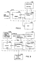
- FIG. 2 shows an expanded schematic of single word adder accumulator 204.
- This accumulator consists of an adder 301 and a latch 302.
- the adder is wired with end around carry in order to sum both negative and positive input numbers.
- Data is received from sine register 202 on the A input terminals of adder 301.
- Data is received from latch 302 on the B terminals of adder 301.
- the resultant sum A + B on the sum terminals of adder 301 is placed on the input terminals of latch 302 and also serves as the output accumulated word to be latched into DAC 205.
- executive control circuit 102 Prior to a computation cycle, executive control circuit 102 places a clear signal on the clear terminal of latch 302. During the first time slot (computation channel), the adjusted sine value for the partial being calculated in that slot appears on the A terminals of adder 301. Since latch 302 has been cleared, zero then appears on the B terminals of adder 301, resulting in an output word equal to the value on the A terminals. At the end of this time slot executive control circuit 102 provides a clock signal to latch 302, thereby clocking the value on its input terminals to its output terminals.
- the adjusted sine value for the partial being calculated in that slot appears on the A terminals of adder 301.
- the output terminals of latch 302 place the value just previously latched on the B terminals of adder 301.
- the sum terminals of adder 301 now contain the sum of the adjusted sine values for the first two time slots.
- latch 302 is again clocked.
- FIG. 3 shows an expanded schematic of the multiple word adder accumulator.
- Multiple word adder accumulator 201 performs its function in the same manner as an adder accumulator except that, as its name implies, it accumulates multiple word sums instead of a single one.
- a word is accumulated for each time slot (computation channel) in the computation cycle (typically thirty-two, although the mechanism will work for any number).
- multiple word adder accumulator 201 is not cleared at the start of each computation cycle but carries the sum forward to the next computation cycle.
- multiple word adder accumulator 201 sums only the repeated addition of the partial pitch coefficient from the coefficient register 200 for each computation channel into a sum word for that same computation channel.
- the data output terminals of partial relative pitch coefficient register 200 are connected to the A input terminals of an adder 401.
- the relative pitch coefficients for the partial being calculated in each computation channel are sequentially applied to adder 401.
- a transparent latch has the property of being transparent (the values on its input terminals appear on its output terminals) when the signal on its clock pin is low. In that mode it acts as a positive logic buffer. When the clock pin is raised high, the data on the input pins at the time of the leading edge are latched to the output pins and as long as the clock pin remains high the output data are constant and unchanging even though the data on the input pins change.
- the data output pins of a register 403 are connected to the input pins of transparent latch 402.
- the A + B sum output pins of adder 401 provide the desired sine table address signal to sine register 202 and the signal on these pins is also applied to the input data pins of register 401. Since only additions are performed and the output desired is of modulo format, the adder is not connected end around carry.
- the same addressing that is used on register 200 is also applied to register 403 so that for each computation channel a particular relative pitch coefficient is supplied by register 200 to adder 401 and a corresponding register word is supplied by register 403 through the transparent latch 402 to adder 401.
- the clock pin on transparent latch 402 is low and the read write pin on register 403 is in the read condition.
- the data in register 403 for that particular time slot is applied through transparent latch 402 (now in the transparent or buffer mode) to the B input data pins of the adder 401.
- the relative pitch coefficient for that partial is produced by relative pitch coefficient register 200 and placed thereby on the A input pins of adder 401.
- the A + B sum from adder 401 is placed on the input pins of register 403, but has no effect during this half cycle since the register 403 is in the read mode and ignores signals on its input pins.
- the clock pin of transparent latch 402 is brought high, thereby locking the data on its output terminals to the value on its input terminals.
- the clock pin on transparent latch 402 is high and the latch remains in latched condition.
- the A + B sum remains the same and is still presented to the input pins of register 403.
- a write signal is applied to register 403, causing the sum A + B to be written into the same register location that contained only B before.
- the register word in register 403 which corresponds to that time slot, accumulates the sum of its prior value plus the corresponding value of the relative pitch coefficient from relative pitch coefficient register 200.
Landscapes
- Physics & Mathematics (AREA)
- Engineering & Computer Science (AREA)
- Acoustics & Sound (AREA)
- Multimedia (AREA)
- Algebra (AREA)
- General Physics & Mathematics (AREA)
- Mathematical Analysis (AREA)
- Mathematical Optimization (AREA)
- Mathematical Physics (AREA)
- Pure & Applied Mathematics (AREA)
- General Engineering & Computer Science (AREA)
- Electrophonic Musical Instruments (AREA)
Applications Claiming Priority (2)
| Application Number | Priority Date | Filing Date | Title |
|---|---|---|---|
| US07/275,932 US4909118A (en) | 1988-11-25 | 1988-11-25 | Real time digital additive synthesizer |
| US275932 | 1988-11-25 |
Publications (2)
| Publication Number | Publication Date |
|---|---|
| EP0370942A2 true EP0370942A2 (de) | 1990-05-30 |
| EP0370942A3 EP0370942A3 (de) | 1991-01-09 |
Family
ID=23054418
Family Applications (1)
| Application Number | Title | Priority Date | Filing Date |
|---|---|---|---|
| EP19890630205 Withdrawn EP0370942A3 (de) | 1988-11-25 | 1989-11-16 | Vorrichtung zur in Echtzeit digitalen additiven Synthese |
Country Status (3)
| Country | Link |
|---|---|
| US (1) | US4909118A (de) |
| EP (1) | EP0370942A3 (de) |
| JP (1) | JPH02187796A (de) |
Families Citing this family (6)
| Publication number | Priority date | Publication date | Assignee | Title |
|---|---|---|---|---|
| US5300724A (en) * | 1989-07-28 | 1994-04-05 | Mark Medovich | Real time programmable, time variant synthesizer |
| US5171930A (en) * | 1990-09-26 | 1992-12-15 | Synchro Voice Inc. | Electroglottograph-driven controller for a MIDI-compatible electronic music synthesizer device |
| WO1992013334A1 (en) * | 1991-01-18 | 1992-08-06 | Mark Zamcheck | Performance controller for music synthesizing system |
| FR2679689B1 (fr) * | 1991-07-26 | 1994-02-25 | Etat Francais | Procede de synthese de sons. |
| US5412152A (en) * | 1991-10-18 | 1995-05-02 | Yamaha Corporation | Device for forming tone source data using analyzed parameters |
| US7563975B2 (en) * | 2005-09-14 | 2009-07-21 | Mattel, Inc. | Music production system |
Family Cites Families (11)
| Publication number | Priority date | Publication date | Assignee | Title |
|---|---|---|---|---|
| US3809786A (en) * | 1972-02-14 | 1974-05-07 | Deutsch Res Lab | Computor organ |
| US3908504A (en) * | 1974-04-19 | 1975-09-30 | Nippon Musical Instruments Mfg | Harmonic modulation and loudness scaling in a computer organ |
| US4150600A (en) * | 1977-05-10 | 1979-04-24 | Nippon Gakki Seizo Kabushiki Kaisha | Computer organ with extended harmonics |
| US4300432A (en) * | 1980-04-14 | 1981-11-17 | Kawai Musical Instrument Mfg. Co., Ltd. | Polyphonic tone synthesizer with loudness spectral variation |
| US4300434A (en) * | 1980-05-16 | 1981-11-17 | Kawai Musical Instrument Mfg. Co., Ltd. | Apparatus for tone generation with combined loudness and formant spectral variation |
| JPS5858595A (ja) * | 1981-10-01 | 1983-04-07 | ヤマハ株式会社 | 電子楽器 |
| JPS6093494A (ja) * | 1983-10-27 | 1985-05-25 | 株式会社河合楽器製作所 | 電子楽器 |
| JPH0642149B2 (ja) * | 1985-04-08 | 1994-06-01 | 株式会社河合楽器製作所 | 電子楽器 |
| US4697490A (en) * | 1986-05-29 | 1987-10-06 | Kawai Musical Instrument Mfg. Co., Ltd. | Musical tone generator using incremental harmonic variation |
| US4735123A (en) * | 1986-10-27 | 1988-04-05 | Kawai Musical Instrument Mfg. Co., Ltd. | Generation of time variant harmonies in an electronic musical instrument |
| US4800794A (en) * | 1987-07-06 | 1989-01-31 | Kawai Musical Instrument Mfg. Co., Ltd. | Harmonic coefficient generator for an electronic musical instrument |
-
1988
- 1988-11-25 US US07/275,932 patent/US4909118A/en not_active Expired - Fee Related
-
1989
- 1989-11-16 EP EP19890630205 patent/EP0370942A3/de not_active Withdrawn
- 1989-11-24 JP JP1303481A patent/JPH02187796A/ja active Pending
Also Published As
| Publication number | Publication date |
|---|---|
| EP0370942A3 (de) | 1991-01-09 |
| US4909118A (en) | 1990-03-20 |
| JPH02187796A (ja) | 1990-07-23 |
Similar Documents
| Publication | Publication Date | Title |
|---|---|---|
| US5301259A (en) | Method and apparatus for generating vocal harmonies | |
| KR0149251B1 (ko) | 악기음 발생 방법 및 시스템과 악기음 발생 제어 시스템 | |
| KR100368046B1 (ko) | 오디오 신호의 음색 및/또는 피치를 변화시키기 위한 방법 및 장치 | |
| CA1172475A (en) | Electronic musical instrument | |
| WO1997017692A9 (en) | Parametric signal modeling musical synthesizer | |
| WO1997017692A1 (en) | Parametric signal modeling musical synthesizer | |
| Massie | Wavetable sampling synthesis | |
| JPH027078B2 (de) | ||
| US4554855A (en) | Partial timbre sound synthesis method and instrument | |
| EP0357096A1 (de) | Elektronisches Musikinstrument mit Benutzung eines Skalatonabstandssystems, um Kollision von Obertönen zu vermeiden | |
| US5306865A (en) | Electronic keyboard musical instrument or tone generator employing Modified Eastern Music Tru-Scale Octave Transformation to avoid overtone collisions | |
| EP0169659B1 (de) | Tongenerator für ein elektroniches Musikinstrument | |
| US4909118A (en) | Real time digital additive synthesizer | |
| US4205577A (en) | Implementation of multiple voices in an electronic musical instrument | |
| US4644839A (en) | Method of synthesizing musical tones | |
| US4177706A (en) | Digital real time music synthesizer | |
| US4084472A (en) | Electronic musical instrument with tone generation by recursive calculation | |
| JPS61204698A (ja) | 楽音信号発生装置 | |
| US5559298A (en) | Waveform read-out system for an electronic musical instrument | |
| JP3334165B2 (ja) | 楽音合成装置 | |
| JPH07111637B2 (ja) | 電子楽器 | |
| JPH02126289A (ja) | 作曲装置 | |
| JPS60126699A (ja) | 電子楽器 | |
| Comerford | Further development of the Bradford musical instrument simulator | |
| JPH0638193B2 (ja) | 電子楽器 |
Legal Events
| Date | Code | Title | Description |
|---|---|---|---|
| PUAI | Public reference made under article 153(3) epc to a published international application that has entered the european phase |
Free format text: ORIGINAL CODE: 0009012 |
|
| AK | Designated contracting states |
Kind code of ref document: A2 Designated state(s): DE FR GB |
|
| PUAL | Search report despatched |
Free format text: ORIGINAL CODE: 0009013 |
|
| AK | Designated contracting states |
Kind code of ref document: A3 Designated state(s): DE FR GB |
|
| STAA | Information on the status of an ep patent application or granted ep patent |
Free format text: STATUS: THE APPLICATION IS DEEMED TO BE WITHDRAWN |
|
| 18D | Application deemed to be withdrawn |
Effective date: 19910710 |