EP0370956A2 - Procédé et dispositif de pliage de pièces en tôle - Google Patents
Procédé et dispositif de pliage de pièces en tôle Download PDFInfo
- Publication number
- EP0370956A2 EP0370956A2 EP89810882A EP89810882A EP0370956A2 EP 0370956 A2 EP0370956 A2 EP 0370956A2 EP 89810882 A EP89810882 A EP 89810882A EP 89810882 A EP89810882 A EP 89810882A EP 0370956 A2 EP0370956 A2 EP 0370956A2
- Authority
- EP
- European Patent Office
- Prior art keywords
- bending
- die
- sheet metal
- piston
- punch
- Prior art date
- Legal status (The legal status is an assumption and is not a legal conclusion. Google has not performed a legal analysis and makes no representation as to the accuracy of the status listed.)
- Granted
Links
- 238000005452 bending Methods 0.000 title claims abstract description 108
- 239000002184 metal Substances 0.000 title claims abstract description 70
- 238000000034 method Methods 0.000 title claims abstract description 29
- 230000003247 decreasing effect Effects 0.000 claims description 2
- 230000003993 interaction Effects 0.000 claims 1
- 210000001550 testis Anatomy 0.000 claims 1
- 238000006073 displacement reaction Methods 0.000 description 3
- 230000000694 effects Effects 0.000 description 2
- 238000003754 machining Methods 0.000 description 2
- 230000001105 regulatory effect Effects 0.000 description 2
- 230000006641 stabilisation Effects 0.000 description 2
- 238000011105 stabilization Methods 0.000 description 2
- 230000000284 resting effect Effects 0.000 description 1
- 238000007789 sealing Methods 0.000 description 1
- 230000001360 synchronised effect Effects 0.000 description 1
Images


Classifications
-
- B—PERFORMING OPERATIONS; TRANSPORTING
- B21—MECHANICAL METAL-WORKING WITHOUT ESSENTIALLY REMOVING MATERIAL; PUNCHING METAL
- B21D—WORKING OR PROCESSING OF SHEET METAL OR METAL TUBES, RODS OR PROFILES WITHOUT ESSENTIALLY REMOVING MATERIAL; PUNCHING METAL
- B21D5/00—Bending sheet metal along straight lines, e.g. to form simple curves
- B21D5/02—Bending sheet metal along straight lines, e.g. to form simple curves on press brakes without making use of clamping means
- B21D5/0272—Deflection compensating means
-
- B—PERFORMING OPERATIONS; TRANSPORTING
- B21—MECHANICAL METAL-WORKING WITHOUT ESSENTIALLY REMOVING MATERIAL; PUNCHING METAL
- B21D—WORKING OR PROCESSING OF SHEET METAL OR METAL TUBES, RODS OR PROFILES WITHOUT ESSENTIALLY REMOVING MATERIAL; PUNCHING METAL
- B21D5/00—Bending sheet metal along straight lines, e.g. to form simple curves
- B21D5/02—Bending sheet metal along straight lines, e.g. to form simple curves on press brakes without making use of clamping means
- B21D5/0209—Tools therefor
-
- B—PERFORMING OPERATIONS; TRANSPORTING
- B21—MECHANICAL METAL-WORKING WITHOUT ESSENTIALLY REMOVING MATERIAL; PUNCHING METAL
- B21D—WORKING OR PROCESSING OF SHEET METAL OR METAL TUBES, RODS OR PROFILES WITHOUT ESSENTIALLY REMOVING MATERIAL; PUNCHING METAL
- B21D5/00—Bending sheet metal along straight lines, e.g. to form simple curves
- B21D5/02—Bending sheet metal along straight lines, e.g. to form simple curves on press brakes without making use of clamping means
- B21D5/0209—Tools therefor
- B21D5/0236—Tool clamping
Definitions
- the present invention relates to a method for bending sheet metal pieces and to a device for carrying out the method.
- press brakes For bending sheet metal pieces, press brakes are used, which have a movable bending punch and a bending die arranged in a die holder, the high working pressures that occur necessitate a heavy type of press brake.
- deflection of the machining tools as a result of deflection of the press frame cannot be prevented.
- deflections naturally impair the accuracy of the bending process and efforts have been made to prevent or compensate for the possible deflections.
- a proposal by the applicant was for the use of a work table, the table top of which rests on a support element corresponding to its length, which is vertically displaceable in a base part and is supported on an oil cushion.
- a further completion of such a press brake was that the die holder was arranged on a number of piston-cylinder units lined up next to one another. If the workpiece to be machined is shorter than the available length of the work table, the workpiece is pressed too hard at the ends and there are inaccuracies.
- a press brake allows a more precise machining, in which the elastically resiliently supported tool itself or its support is formed from a number of sub-elements which are arranged next to one another independently of one another in a vertically displaceable manner. Under the load, only those sub-elements are shifted against the elastic base on which the workpiece rests directly or indirectly.
- it is advantageous if the die holder rests on a number of piston-cylinder units lined up next to one another, while the bending die is provided with an adjustable base, so that any angle can be set by the base adjustment.
- a method for bending pieces of sheet metal with a bending punch and a bending die is now assumed, the bending die having a height-adjustable base and the die holder or the punch or punch holder resting on a number of piston-cylinder units lined up next to one another.
- Claim 3 contains a variant of the method.
- a particular advantage of the proposed method is that even extremely narrow sheet metal strips can be processed with great precision without one-sided displacements or unstabilities occurring.
- the sheet metal piece is pressed continuously and with constant pressure against the die base. In this way, a constant bending angle is ensured over the entire bending length, regardless of whether the sheet length corresponds to the length of the bending punch, is shorter than the bending punch or is significantly shorter than the bending punch.
- the pressure of the corresponding piston-cylinder units is varied.
- the die base in the area of the piston-cylinder units lying on the left and right is increased by the sheet thickness, provided that these piston-cylinder units arranged on both sides are outside the area of the sheet-metal piece.
- the corresponding segments of the bending die i.e. those segments that lie in the area of the two piston-cylinder units on the right and left, can be reduced by the sheet thickness, provided that the sheet metal piece is narrow and in the area of there is no sheet metal in the outermost piston-cylinder units.
- the air gap at both ends of the bending punch is bridged between the bending punch and the bending die, firstly by raising the bottom of the bending die and alternatively by lowering the corresponding segments of the bending die, so that the high forces occurring during bending cannot cause instability.
- the remaining units which are also outside the area of the sheet metal piece, are relieved.
- a device for performing the method is defined in claim 7, with further optional features of the device being contained in claims 8-12.
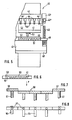
- a press brake which has a hydraulically operated ram 2, which is provided with a bending punch 3.
- the bending punch 3 is in one piece or composed of individual segments 4.
- a length adjustment of the stamp 3 is made possible by adding or omitting segments 4.
- the bending die 3 interacts with a bending die 5, which is arranged in a die holder 6 and has a height-adjustable bottom, also consisting of individual segments, which is then used in Ver 4 is described and explained in more detail.
- the die holder 6 rests on a number of piston-cylinder units 7 lined up next to one another, which can be actuated individually or together, as will be described later.
- the sheet metal piece 8 there is a sheet metal piece 8 between the punch 3 and the bending die 5, which is very narrow in relation to the length of the ram 2.
- the thickness of the sheet metal piece 8 is of course only a few millimeters, but is drawn in a greatly exaggerated manner in the drawing to explain the problems.
- the two piston-cylinder units 7a, 7b are located below the sheet metal piece 8.
- Air bending force is the force that is required to deform the sheet metal piece, which initially lies flat on the die 5 and is pressed into the die 5.
- This air bending force is the pressing pressure required to deform the sheet metal piece 8, namely until the sheet metal piece touches the bottom of the die 5. After the bending edge lies on the base of the die, this provides resistance, which leads to an increase in the pressing pressure.
- the height-adjustable bottom of the bending die is previously adjusted to the bending angle adjusted accordingly, this setting can be done in a known manner by means of adjustable wedges.
- the bottom of the die 5 is increased at both ends at 5 'by the sheet thickness h.
- the air gap is bridged at both ends of the die 5 and the bending punch 3 is supported in a stable manner.
- the bottom of the die is increased at both ends of the die 5 by separate wedges, not shown, which can be actuated by an adjusting spindle.
- the spindles are expediently driven by a motor and precisely adjusted. This arrangement will be explained in more detail later.
- FIG. 2 Another possibility is shown in FIG. 2.
- the die is designated by 5 and the die holder by 6.
- sheet metal style 8 which e.g. 1 is identical to that described in FIG. 1, with the difference that to stabilize the bending die 3, the two outer segments 4a and 4b of the die 3 downward by the sheet thickness h be moved.
- FIG. 3 Another possibility is shown in FIG. 3.
- a threaded spindle 9 is arranged on the ram 2 of the press brake on both ends of the same on the right and left, which are adjustable in a holder 10 fastened to the ram 2.
- a stop 10 ' is laterally arranged in synchronism with the die bottom on the die holder 6. against these stops 10 'act the threaded spindles 9, which are set so that at both ends of the punch 3 an air gap 11' remains, the height of which corresponds to the sheet thickness h.
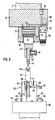
- FIG. 4 shows a device which is particularly suitable for carrying out the described method, the design of the die and the die holder and a piston-cylinder unit being shown in more detail.
- a number of piston-cylinder units are arranged, which are arranged closely next to each other and each have a cylinder 12 with stepped pistons 13, 14.
- the piston part 13 is in the usual manner Cylinder 12 is guided, while the piston part 14, whose diameter is smaller than that of the piston part 13, is arranged in a cover 15, which cover is annular and is provided with sealing rings 16.
- the lid 15 also has a downwardly facing ring extension 17 which extends into the interior of the cylinder 12 and with its edge 17 'forms a stop for the top dead center position of the cylinder part 13.
- the lower stroke limitation is the corresponding surface 11a of the support plate 11. In this way, a piston stroke H remains.
- a pressure channel 18 is provided in the stationary support plate 11 and is connected to a pressure source.
- Another pressure line 19 leads from the channel 18 into a three-way valve 20, which connects the line 19 with a line 21 in one position and the line 21 with a return channel 24 in the other position.
- the line 21 leads into the space 23 below the piston part 13, while the line 22 is a return line to the return channel 24.
- a common table top 25 is provided, which rests on the various piston-cylinder units arranged next to one another, specifically on the facing surfaces 14 'of the piston parts 14 and serves to receive the die holder 26.
- the die 27 is arranged, which is provided with an adjustable die bottom 28.
- the die bottom 28 is expediently from pin-shaped inserts 29, which are accommodated in bores of the die holder and protrude into the cutout 27 'of the die 27 above. With their lower end they rest on the surface of a carrier 30, which can be adjusted in height with the aid of a wedge 31.
- Spindles 32 with regulating members 33 are used for wedge adjustment.
- the die 27 together with the wedge adjustment is accommodated on or in the die holder 26, which is fastened on the continuous table top 25 by means of clamping members 34.
- the die holder 26 can be displaceable and adjustable in the horizontal plane, so that the die 27 can be displaced relative to the plunger 2, not shown in this FIG. 4, by the displacement of the die holder 26.
- a spindle (not shown in detail) can be provided for the displacement.
- the proposed method can be carried out in a simple manner.
- the three-way valve 20 connects the pressure line 19 to the line 21, which opens into the space 23.
- the stepped piston 13, 14 is in the upper end position, as can be seen in FIG. 4.
- the shoulder 13 'of the piston part 13 will abut against the ring edge 17' of the extension 17.
- the pressure acting on the stepped piston 13, 14 in the space 23 is somewhat greater than the air bending force required for bending, so that the stepped piston 13, 14 remains in the illustrated top dead center position during air bending.
- the stabilization measures mentioned take effect at both ends of the die.
- the two ends of the bending punch, not shown, abut corresponding stops which are arranged for compensation.
- Either parts of the die base 28 are raised at the corresponding points or segments of the ram are lowered. In this way, the thickness of the sheet metal piece is compensated so that the entire press brake remains stable.
- the remaining step pistons 13, 14, which are not under the sheet, are relieved.
- step pistons 13, 14 it is also possible for the step pistons 13, 14 to be in the bottom dead center position without pressure in the starting position.
- the bending of the sheet metal piece is carried out with the bending punch, the plunger being stopped before reaching the die bottom 28.
- the pistons 13, 14 are then pressurized so that they press the entire die 27 together with the adjustable die bottom 28 against the sheet metal piece with constant pressure, whereupon there is a uniform deformation along the bending edge of the punch.
- the die base 28 remains in the desired position during the entire operation.
- each stepped piston 13, 14 can be pressurized and controlled separately and independently of the others. The individual control makes it possible to compensate for unevenness in the nature of the piece of sheet metal to be bent by locally increasing or decreasing the pressure.
- the die holder rests on a number of piston-cylinder units lined up next to one another.
- the bending punch or the bending punch holder it is possible for the bending punch or the bending punch holder to be supported with the aid of piston-cylinder units lined up next to one another.
- FIG. 5 Here is designated the press brake with 40, which is equipped with a punch 41, which is received in a punch holder 42.
- the punch holder 42 is arranged on the ram 43 of the press brake with the aid of piston-cylinder units 44.
- the design of the piston-cylinder units 44 corresponds to the design described above.
- a piston-cylinder unit 14 ' is arranged in a holding arm 42'.
- a bending die 46 works together with the bending die 41 and is arranged in a die holder 47 on a table 48. At both ends of the bending die 46, a holder 49 is arranged for the adjustable reception of a threaded spindle 45 each, which extend into the movement path of the two piston-cylinder units 14 '.
- the brackets 49 are adjusted synchronously with the height-adjustable bottom parts of the die 46, which are on the outside on both sides, as will be explained in more detail below.
- This height-adjustable die base is designated 50 in FIG. 5 and is shown in more detail in FIGS. 6, 7 and 8.
- the upper ends of the pins 51 are expediently provided with square heads 52, which together form a smooth surface of the die base.
- the starting position can be seen in FIG. 5, where all the pins 51 are at the same altitude take and their heads 52 define the flat die bottom 50.
- the height of the pins 51 can be adjusted by means of wedges 54 which can be adjusted jointly or individually.
- FIG. 8 schematically shows a view of FIG.
- FIGS. 6 and 7 show that the two outer pins 51 with heads 52 assume a higher position than the rest.
- the brackets 49 are adjusted synchronously with these.
- the height of the adjustable base 50 of the bending die 46 is first adjusted exactly to the bending angle.
- the punch 41 is lowered while the piston-cylinder units 44 have a pressure which is greater than the pressure required for air bending.
- the two lateral piston-cylinder units 44 ' which act as stops, abut against the upper ends of the precisely adjusted threaded spindles 45.
- the air bending is ended and the bending edge of the sheet metal piece 53 abuts on the die base 50, the pistons of the piston-cylinder units 44 located in the region of the sheet-metal piece 53 and the pistons of the two laterally outermost piston-cylinder units 44 'being pushed back.
- piston-cylinder units 44 are held in the top dead center position without pressure during the air bending, after which the punch 41 is stopped before reaching the die bottom. Then the pistons of the piston-cylinder units 44, which are located above the sheet metal piece 53 and the two outermost units 44 'are pressurized so that they press the punch 41 against the bending edge or against the stops 49 with constant pressure.
- FIG. 6 A variant is shown in Figures 6 and 7.
- the die base 50 is increased by the sheet thickness of the sheet metal piece 53 in the region of the piston-cylinder units lying on the extreme left and right. This position can be seen from FIG. 6 and in an enlarged view from FIG. 7.
- the die base is increased at the corresponding points by adjusting the corresponding wedges 54 under the two outer pins 51.
- FIG. 9 A somewhat more detailed illustration of the device described last can be seen in FIG. 9.
- the parts which are already shown in FIG. 4 have been given the same reference numerals.
- the press brake shown is provided with a die 27 with an adjustable die bottom 28, in which in turn pin-shaped inserts 29 rest against a carrier 30 which can be adjusted with the aid of a wedge system 31 by transverse spindles 32 with regulating members 33.
- the parts mentioned are arranged in a die holder 26, in which, as already described, there is an additional wedge system 35 which can be actuated by a spindle 36 with a motor 37.
- the two clamping members 34 serve to fasten the die holder on the table 58 of the press brake.
- a punch 41 interacts with the die 27 and is fastened in the punch holder 42 with the aid of a fastening device 56.
- This is arranged on the piston part 14 of the stepped piston 13, 14.
- the ram 2 of the press brake is provided with a support plate 11, on which a number of cylinders 12 are provided side by side.
- a stepped piston 13, 14 is guided in each cylinder 12, which collectively hold the punch holder 42 with the bending punch 41.
Landscapes
- Engineering & Computer Science (AREA)
- Mechanical Engineering (AREA)
- Bending Of Plates, Rods, And Pipes (AREA)
- Shaping Of Tube Ends By Bending Or Straightening (AREA)
Applications Claiming Priority (2)
| Application Number | Priority Date | Filing Date | Title |
|---|---|---|---|
| AT2842/88 | 1988-11-21 | ||
| AT0284288A AT392023B (de) | 1988-11-21 | 1988-11-21 | Verfahren zum biegen von blechstuecken |
Publications (3)
| Publication Number | Publication Date |
|---|---|
| EP0370956A2 true EP0370956A2 (fr) | 1990-05-30 |
| EP0370956A3 EP0370956A3 (fr) | 1991-05-02 |
| EP0370956B1 EP0370956B1 (fr) | 1993-09-08 |
Family
ID=3541164
Family Applications (1)
| Application Number | Title | Priority Date | Filing Date |
|---|---|---|---|
| EP89810882A Expired - Lifetime EP0370956B1 (fr) | 1988-11-21 | 1989-11-20 | Procédé et dispositif de pliage de pièces en tôle |
Country Status (6)
| Country | Link |
|---|---|
| US (1) | US5097694A (fr) |
| EP (1) | EP0370956B1 (fr) |
| JP (2) | JPH02160120A (fr) |
| AT (2) | AT392023B (fr) |
| DE (1) | DE58905534D1 (fr) |
| ES (1) | ES2043097T3 (fr) |
Cited By (3)
| Publication number | Priority date | Publication date | Assignee | Title |
|---|---|---|---|---|
| EP0624411A1 (fr) * | 1993-05-13 | 1994-11-17 | Hämmerle Ag | Procédé pour plier des tôles et presse à plier pour la mise en oeuvre du procédé |
| FR2708219A1 (fr) * | 1993-07-27 | 1995-02-03 | Amada Europ Sa | Procédé de compensation des déformations des tabliers de presses hydrauliques, tabliers et presses hydrauliques ainsi équipés. |
| EP2210681A3 (fr) * | 2009-01-27 | 2013-05-22 | Trumpf Maschinen Austria GmbH & CO. KG. | Presse à plier dotée d'une barre de pressage en plusieurs parties |
Families Citing this family (6)
| Publication number | Priority date | Publication date | Assignee | Title |
|---|---|---|---|---|
| US5969973A (en) * | 1994-11-09 | 1999-10-19 | Amada Company, Ltd. | Intelligent system for generating and executing a sheet metal bending plan |
| EP0841106A1 (fr) * | 1996-11-12 | 1998-05-13 | Maru Kikai Kogyo Co., Ltd. | Presse plieuse |
| US20070056348A1 (en) * | 2005-09-09 | 2007-03-15 | David Leland | Brake punch inserts |
| NL2006854C2 (nl) * | 2011-05-26 | 2012-12-05 | Wila Bv | Werkwijze en inrichting voor het compenseren van afwijkingen bij een vervormende bewerking tussen twee balken van een pers. |
| AT512465B1 (de) * | 2012-02-10 | 2014-01-15 | Trumpf Maschinen Austria Gmbh | Presstisch oder pressbalken mit verstellbarem balkenelement |
| CN116475307B (zh) * | 2023-04-23 | 2024-03-19 | 宝玛克(合肥)科技有限公司 | 一种辊压件在线翻孔模具及其使用方法 |
Family Cites Families (14)
| Publication number | Priority date | Publication date | Assignee | Title |
|---|---|---|---|---|
| US3677009A (en) * | 1970-11-12 | 1972-07-18 | Kelso Marine Inc | Control arrangement for the male die of a hydraulic press brake |
| FR2119528A5 (fr) * | 1970-12-25 | 1972-08-04 | Amada Co Ltd | |
| AT332703B (de) * | 1974-05-27 | 1976-10-11 | Haemmerle Ag Maschf | Arbeitstisch an blechbearbeitungsmaschinen |
| NL179349C (nl) * | 1975-06-24 | Haemmerle Ag Maschf | Buigwerktuig. | |
| AT343435B (de) * | 1976-04-02 | 1978-05-26 | Haemmerle Ag Maschf | Abkantpresse mit arbeitstisch |
| DE2631292A1 (de) * | 1976-07-12 | 1978-01-19 | Bauer Guenter | Vorrichtung zum abkanten von blechen |
| DE2714958C2 (de) * | 1977-04-02 | 1983-01-27 | G. Siempelkamp Gmbh & Co, 4150 Krefeld | Hydraulische Blechbiegepresse |
| JPS54417A (en) * | 1977-06-03 | 1979-01-05 | Hayashigumi Kk | Method of construction of pressing in presssin pipe |
| DE3245755A1 (de) * | 1982-12-10 | 1984-06-14 | Dorstener Maschinenfabrik Ag, 4270 Dorsten | Verfahren zum korrigieren der biegelinie des biegewerkzeuges einer biegepresse, insbesondere abkantpresse |
| JPS59212121A (ja) * | 1983-05-17 | 1984-12-01 | Amada Co Ltd | プレスブレーキ |
| JPS6037195U (ja) * | 1983-08-19 | 1985-03-14 | 三洋電機株式会社 | 電磁調理器 |
| DE3546815C2 (fr) * | 1984-03-30 | 1993-01-28 | Amada Co., Ltd., Isehara, Kanagawa, Jp | |
| FR2597013B1 (fr) * | 1986-04-11 | 1994-05-27 | Amada Co Ltd | Cintreuse de plaques |
| JPS63157800A (ja) * | 1987-11-06 | 1988-06-30 | Amino Tekkosho:Kk | プレス機におけるスライドの動的平衡精度維持装置 |
-
1988
- 1988-11-21 AT AT0284288A patent/AT392023B/de not_active IP Right Cessation
-
1989
- 1989-11-16 JP JP1296313A patent/JPH02160120A/ja active Pending
- 1989-11-17 US US07/438,516 patent/US5097694A/en not_active Expired - Fee Related
- 1989-11-20 DE DE89810882T patent/DE58905534D1/de not_active Expired - Fee Related
- 1989-11-20 AT AT89810882T patent/ATE94095T1/de active
- 1989-11-20 ES ES89810882T patent/ES2043097T3/es not_active Expired - Lifetime
- 1989-11-20 EP EP89810882A patent/EP0370956B1/fr not_active Expired - Lifetime
-
1995
- 1995-07-26 JP JP1995009029U patent/JP2518512Y2/ja not_active Expired - Lifetime
Cited By (3)
| Publication number | Priority date | Publication date | Assignee | Title |
|---|---|---|---|---|
| EP0624411A1 (fr) * | 1993-05-13 | 1994-11-17 | Hämmerle Ag | Procédé pour plier des tôles et presse à plier pour la mise en oeuvre du procédé |
| FR2708219A1 (fr) * | 1993-07-27 | 1995-02-03 | Amada Europ Sa | Procédé de compensation des déformations des tabliers de presses hydrauliques, tabliers et presses hydrauliques ainsi équipés. |
| EP2210681A3 (fr) * | 2009-01-27 | 2013-05-22 | Trumpf Maschinen Austria GmbH & CO. KG. | Presse à plier dotée d'une barre de pressage en plusieurs parties |
Also Published As
| Publication number | Publication date |
|---|---|
| JPH02160120A (ja) | 1990-06-20 |
| EP0370956A3 (fr) | 1991-05-02 |
| ATA284288A (de) | 1990-07-15 |
| JPH08537U (ja) | 1996-03-26 |
| US5097694A (en) | 1992-03-24 |
| JP2518512Y2 (ja) | 1996-11-27 |
| DE58905534D1 (de) | 1993-10-14 |
| ES2043097T3 (es) | 1993-12-16 |
| EP0370956B1 (fr) | 1993-09-08 |
| AT392023B (de) | 1991-01-10 |
| ATE94095T1 (de) | 1993-09-15 |
Similar Documents
| Publication | Publication Date | Title |
|---|---|---|
| EP0453955B1 (fr) | Dispositif pour emboutir des pièces de tôle dans une presse | |
| DE102007033199B3 (de) | Verfahren und Biegemaschine zur Kompensation der Durchbiegung von Teilen dieser Biegemaschine | |
| DE3325305C2 (de) | Pressenrahmen | |
| EP0173755B1 (fr) | Dispositif d'étirage dans une presse | |
| EP2210681B1 (fr) | Presse à plier dotée d'une barre de pressage en plusieurs parties | |
| DE3008947A1 (de) | Mechanische presse | |
| DE2830779C2 (de) | Hydraulische Doppeldruckpresse | |
| DE4112656A1 (de) | Zieheinrichtung in einer presse zum ziehen von blechformteilen | |
| EP0370956B1 (fr) | Procédé et dispositif de pliage de pièces en tôle | |
| EP3160726B1 (fr) | Presse à châssis en c, améliorée | |
| EP1252010B1 (fr) | Presse | |
| DE19928422A1 (de) | Presse zum Außenhochdruckformen | |
| DE3002039A1 (de) | Stehende hydraulische gesenkpresse | |
| DE4434419A1 (de) | Mechanische und hydraulische Pressen | |
| DE4016838A1 (de) | Ziehapparat in einer presse | |
| DE10249809B4 (de) | Presse | |
| EP1799372B1 (fr) | Procede et dispositif pour la fabrication et/ou l'usinage de pieces | |
| DE3233860A1 (de) | Einrichtung zur parallelhaltung des stoessels an hydraulischen stanzpressen | |
| DE10215003A1 (de) | Hydraulische Presse | |
| DE3424262C2 (fr) | ||
| DE102024115234B4 (de) | Presse, insbesondere zum Entgraten eines Werkstücks | |
| EP0128342B1 (fr) | Presse avec un dispositif pour l'éjection des pièces et un dispositif pour l'ajustage de l'altitude de fermeture | |
| EP1055510A2 (fr) | Dispositif de compensation de la déformation d'une installation à plaque et procédé associé | |
| DE19605782A1 (de) | Presse | |
| DE3504057C2 (de) | Werkzeug zur spanlosen Blechbearbeitung, insbesondere zum Tiefziehen, Abkanten od. dgl. |
Legal Events
| Date | Code | Title | Description |
|---|---|---|---|
| PUAI | Public reference made under article 153(3) epc to a published international application that has entered the european phase |
Free format text: ORIGINAL CODE: 0009012 |
|
| AK | Designated contracting states |
Kind code of ref document: A2 Designated state(s): AT BE CH DE ES FR GB GR IT LI LU NL SE |
|
| PUAL | Search report despatched |
Free format text: ORIGINAL CODE: 0009013 |
|
| AK | Designated contracting states |
Kind code of ref document: A3 Designated state(s): AT BE CH DE ES FR GB GR IT LI LU NL SE |
|
| 17P | Request for examination filed |
Effective date: 19910607 |
|
| 17Q | First examination report despatched |
Effective date: 19920406 |
|
| GRAA | (expected) grant |
Free format text: ORIGINAL CODE: 0009210 |
|
| AK | Designated contracting states |
Kind code of ref document: B1 Designated state(s): AT BE CH DE ES FR GB GR IT LI LU NL SE |
|
| PG25 | Lapsed in a contracting state [announced via postgrant information from national office to epo] |
Ref country code: GR Free format text: LAPSE BECAUSE OF FAILURE TO SUBMIT A TRANSLATION OF THE DESCRIPTION OR TO PAY THE FEE WITHIN THE PRESCRIBED TIME-LIMIT Effective date: 19930908 |
|
| REF | Corresponds to: |
Ref document number: 94095 Country of ref document: AT Date of ref document: 19930915 Kind code of ref document: T |
|
| ITF | It: translation for a ep patent filed | ||
| PGFP | Annual fee paid to national office [announced via postgrant information from national office to epo] |
Ref country code: FR Payment date: 19931011 Year of fee payment: 5 |
|
| PGFP | Annual fee paid to national office [announced via postgrant information from national office to epo] |
Ref country code: CH Payment date: 19931012 Year of fee payment: 5 Ref country code: AT Payment date: 19931012 Year of fee payment: 5 |
|
| PGFP | Annual fee paid to national office [announced via postgrant information from national office to epo] |
Ref country code: GB Payment date: 19931013 Year of fee payment: 5 |
|
| REF | Corresponds to: |
Ref document number: 58905534 Country of ref document: DE Date of ref document: 19931014 |
|
| PGFP | Annual fee paid to national office [announced via postgrant information from national office to epo] |
Ref country code: SE Payment date: 19931015 Year of fee payment: 5 |
|
| PGFP | Annual fee paid to national office [announced via postgrant information from national office to epo] |
Ref country code: DE Payment date: 19931020 Year of fee payment: 5 |
|
| GBT | Gb: translation of ep patent filed (gb section 77(6)(a)/1977) |
Effective date: 19930923 |
|
| PGFP | Annual fee paid to national office [announced via postgrant information from national office to epo] |
Ref country code: BE Payment date: 19931027 Year of fee payment: 5 |
|
| PGFP | Annual fee paid to national office [announced via postgrant information from national office to epo] |
Ref country code: LU Payment date: 19931101 Year of fee payment: 5 |
|
| PGFP | Annual fee paid to national office [announced via postgrant information from national office to epo] |
Ref country code: ES Payment date: 19931110 Year of fee payment: 5 |
|
| ET | Fr: translation filed | ||
| PGFP | Annual fee paid to national office [announced via postgrant information from national office to epo] |
Ref country code: NL Payment date: 19931130 Year of fee payment: 5 |
|
| REG | Reference to a national code |
Ref country code: ES Ref legal event code: FG2A Ref document number: 2043097 Country of ref document: ES Kind code of ref document: T3 |
|
| EPTA | Lu: last paid annual fee | ||
| PLBE | No opposition filed within time limit |
Free format text: ORIGINAL CODE: 0009261 |
|
| STAA | Information on the status of an ep patent application or granted ep patent |
Free format text: STATUS: NO OPPOSITION FILED WITHIN TIME LIMIT |
|
| 26N | No opposition filed | ||
| PG25 | Lapsed in a contracting state [announced via postgrant information from national office to epo] |
Ref country code: LU Free format text: LAPSE BECAUSE OF NON-PAYMENT OF DUE FEES Effective date: 19941120 Ref country code: GB Effective date: 19941120 Ref country code: AT Effective date: 19941120 |
|
| PG25 | Lapsed in a contracting state [announced via postgrant information from national office to epo] |
Ref country code: SE Effective date: 19941121 Ref country code: ES Free format text: LAPSE BECAUSE OF THE APPLICANT RENOUNCES Effective date: 19941121 |
|
| PG25 | Lapsed in a contracting state [announced via postgrant information from national office to epo] |
Ref country code: LI Effective date: 19941130 Ref country code: CH Effective date: 19941130 Ref country code: BE Effective date: 19941130 |
|
| EAL | Se: european patent in force in sweden |
Ref document number: 89810882.4 |
|
| BERE | Be: lapsed |
Owner name: HAEMMERLE A.G. Effective date: 19941130 |
|
| PG25 | Lapsed in a contracting state [announced via postgrant information from national office to epo] |
Ref country code: NL Effective date: 19950601 |
|
| NLV4 | Nl: lapsed or anulled due to non-payment of the annual fee | ||
| GBPC | Gb: european patent ceased through non-payment of renewal fee |
Effective date: 19941120 |
|
| PG25 | Lapsed in a contracting state [announced via postgrant information from national office to epo] |
Ref country code: FR Effective date: 19950731 |
|
| REG | Reference to a national code |
Ref country code: CH Ref legal event code: PL |
|
| PG25 | Lapsed in a contracting state [announced via postgrant information from national office to epo] |
Ref country code: DE Effective date: 19950801 |
|
| EUG | Se: european patent has lapsed |
Ref document number: 89810882.4 |
|
| REG | Reference to a national code |
Ref country code: FR Ref legal event code: ST |
|
| REG | Reference to a national code |
Ref country code: ES Ref legal event code: FD2A Effective date: 20010402 |
|
| PG25 | Lapsed in a contracting state [announced via postgrant information from national office to epo] |
Ref country code: IT Free format text: LAPSE BECAUSE OF NON-PAYMENT OF DUE FEES Effective date: 20051120 |