EP0841106A1 - Presse plieuse - Google Patents
Presse plieuse Download PDFInfo
- Publication number
- EP0841106A1 EP0841106A1 EP97630025A EP97630025A EP0841106A1 EP 0841106 A1 EP0841106 A1 EP 0841106A1 EP 97630025 A EP97630025 A EP 97630025A EP 97630025 A EP97630025 A EP 97630025A EP 0841106 A1 EP0841106 A1 EP 0841106A1
- Authority
- EP
- European Patent Office
- Prior art keywords
- upper tool
- bending
- length
- pressure
- spacer
- Prior art date
- Legal status (The legal status is an assumption and is not a legal conclusion. Google has not performed a legal analysis and makes no representation as to the accuracy of the status listed.)
- Ceased
Links
- 125000006850 spacer group Chemical class 0.000 claims abstract description 69
- 238000005452 bending Methods 0.000 claims abstract description 68
- 230000005540 biological transmission Effects 0.000 claims abstract description 23
- 230000000694 effects Effects 0.000 claims abstract description 14
- 238000000034 method Methods 0.000 claims description 19
- 230000008569 process Effects 0.000 claims description 18
- 241000669003 Aspidiotus destructor Species 0.000 claims description 9
- 239000012530 fluid Substances 0.000 claims description 7
- 230000003028 elevating effect Effects 0.000 claims description 2
- 238000004804 winding Methods 0.000 claims description 2
- 239000011295 pitch Substances 0.000 description 9
- 230000001788 irregular Effects 0.000 description 6
- 238000010276 construction Methods 0.000 description 3
- 230000000630 rising effect Effects 0.000 description 3
- 230000008859 change Effects 0.000 description 2
- 230000008878 coupling Effects 0.000 description 2
- 238000010168 coupling process Methods 0.000 description 2
- 238000005859 coupling reaction Methods 0.000 description 2
- 230000007246 mechanism Effects 0.000 description 2
- 229910001220 stainless steel Inorganic materials 0.000 description 2
- 239000010935 stainless steel Substances 0.000 description 2
- 230000000153 supplemental effect Effects 0.000 description 2
- 244000261422 Lysimachia clethroides Species 0.000 description 1
- 239000007788 liquid Substances 0.000 description 1
- 230000009467 reduction Effects 0.000 description 1
Images


Classifications
-
- B—PERFORMING OPERATIONS; TRANSPORTING
- B21—MECHANICAL METAL-WORKING WITHOUT ESSENTIALLY REMOVING MATERIAL; PUNCHING METAL
- B21D—WORKING OR PROCESSING OF SHEET METAL OR METAL TUBES, RODS OR PROFILES WITHOUT ESSENTIALLY REMOVING MATERIAL; PUNCHING METAL
- B21D5/00—Bending sheet metal along straight lines, e.g. to form simple curves
- B21D5/02—Bending sheet metal along straight lines, e.g. to form simple curves on press brakes without making use of clamping means
-
- B—PERFORMING OPERATIONS; TRANSPORTING
- B21—MECHANICAL METAL-WORKING WITHOUT ESSENTIALLY REMOVING MATERIAL; PUNCHING METAL
- B21D—WORKING OR PROCESSING OF SHEET METAL OR METAL TUBES, RODS OR PROFILES WITHOUT ESSENTIALLY REMOVING MATERIAL; PUNCHING METAL
- B21D5/00—Bending sheet metal along straight lines, e.g. to form simple curves
- B21D5/002—Positioning devices
Definitions
- the present invention relates to a press brake, and in particular relates to the press brake for bending a work sheet wherein an optional effective upper tool (upper die) length to be transmitted a pressure can be set from a machine center line and the upper tool portion other than the optional length can be prevented from receiving a transmission of the pressure .
- an optional effective upper tool (upper die) length to be transmitted a pressure can be set from a machine center line and the upper tool portion other than the optional length can be prevented from receiving a transmission of the pressure .
- a tool height in respect of the tool length direction is corrected to a convex height by an equipment of a wedge on a lower tool so as to make the bent condition of the ram during a process coincidence with a lower tool line.
- a lower limit control valve has been attached on members to be separately mounted for being not effected by a distortion and the work sheet has been processed by pressurizing a maximum pressure having a disregard of a side frame distortion caused by pressurizing.
- a hydraulic cushion is contained in a split tool upper portion or a lower portion so that a pressure per a work sheet length is made uniform to eliminate a clearance between the upper and the lower tools by the hydraulic cushion function, i.e. the press brake is known that the pressure is adjusted according to a sheet thickness and a V-shape groove width or the work sheet can be bent precisely by a uniform pressure having a disregard of a bending length.
- pressure providing members are arranged at 25mm pitch distance in a split tool inside to correspond with each 100mm width standard tool by respective four pins.
- an excess pressure is applied thereon, for example twice pressure is applied on the sheet set on the standard 50mm width tool , therefore the split tool which may contact with the work sheet end is preliminarily removed or an exchanging to shorter length split tool or to a specific width tool has been tried.
- a press brake of a bending machine for a precise bending process in preventing an appearance of irregular portion on a bending line wherein an effect length of upper tools can be adjusted by constructing single and uniform upper tool relating to full length of the machine width.
- an upper tool is mounted in an upper tool holder at a ram bottom end via a cushion provided in the holder and a bending angle of a work sheet is determined by three points such as both shoulders of the lower tool and a lower tool bottom of which height can be adjusted, characterized in that a group of pins (40) as a pressure transmission member arranged at symmetrical positions at certain pitch distance from a machine center line (80) of the upper tool holder (11) inside , a block type pressure providing member (25) including a hydraulic chamber (21) and a rubber sheet (23) and disposed at a lower portion of a hydraulic cushion (20) , a series of spacers (37) arranged in capable putting in and out from the clearance between the pressure providing member (25) and a group of pins and a spacer moving means (30) are provided.
- a group of pins (40) as a pressure transmission member arranged at symmetrical positions at certain pitch distance from a machine center line (80) of the upper tool holder (11) inside
- a press brake for bending a work sheet consists of a ram (10) elevating by an actuation of a main cylinder, a upper tool holder (11) fixed on a bottom end of the ram, a hydraulic cushion (20) formed by a hydraulic chamber which is arranged over full length of the upper tool holder and a rubber sheet, a pressure providing member (25) arranged at the bottom portion of the hydraulic cushion, an upper tool (12) mounted on the bottom portion of the upper tool holder, a bed (13) and a lower tool (14) mounted on the bed upper surface and having both shoulders (57, 58) and a lower tool bottom member (54) of which height can be adjusted , wherein the upper tool is pressurized by pressing down the ram and a bending angle of the work sheet is determined by three points of both shoulders (57, 58) of the lower tool and the lower tcol bottom member (54) which height is adjusted in a condition of providing a uniform hydraulic pressure on the die under the process of the actuation of
- an effect upper tool length can be changed automatically corresponding to the bending length of the work sheet without distinction of upper tool constructions such as a single and uniform upper tool for a full length of the machine width or a combination of split upper tools , Therefore a plurality group of pins (pressure transmission member) are aligned between the pressure providing member and upper tools to activate as the pressure transmission member for the upper tool length corresponding to the bending length of the work sheet, while the upper tool portion other than the above are not effected by a pressure from the pressure providing member.
- the upper tool holder (11) includes a plurality of pressure transmission pins (40) symmetrically mounted with a certain pitch distance at left and right positions from a mechanical center line (80) between the pressure providing member (25) and the upper tool (12), clearance (48) formed between a lower surface of the pressure providing member (25) and an upper surface of each pressure transmission pin (40), a series of spacers (37) arranged and connected by a chain (35) for inserting into the clearance (48), and a spacer moving means (30) capable of orderly inserting a predetermined number of spacers (37) in the clearance (48) at the upper surface of each pressure transmission pin (40) through the selected position from the mechanical center line for keeping an effect length of the upper tool to correspond with the bending length of the work sheet.
- each of pressure transmission pins (40, 40a, 40b) is inserted into a plurality of holes (46) opened at a lower portion of a vacant space (24) for containing the pressure providing member of the holder (11) inside, respective two pins (40a, 40b) of left and right sides adjacent to the machine center line (80) are not received the spacer and said pins contact with a lower surface of the block type pressure providing member (25), while a plurality of pins (40) arranged outward from said pins (40a, 40b) are formed a height lower in proportional to a length through the spacer is inserted and are received a pressure from the pressure providing member (25) via the spacer which is inserted into the pin upper surface so as to transmit the pressure to the upper tool of that portion.
- respective left and right side several pins (40a, 40a, 40b, 40b) adjacent to the machine center line (80) are formed in a standard height from the lower surface of the pressure providing member (25) to the upper surface of the upper tool (12) and do not receive the spacer (37) so as to transmit a pressure from the pressure providing member (25) to the upper tool of that portion.
- a plurality of pins (40) are arranged toward left and right dies longitudinal direction outside from pins (40b, 40b) having a standard height are formed in a lower height in proportional to the thickness of the spacer than pins (40b, 40b) so as to transmit a pressure from the pressure providing member (25) via the spacer to the upper tool at that portion.
- the spacer moving means (30) comprises a pair of sprockets (33, 34) symmetrically arranged left and right side of the mechanical center line (80), a pair of endless chains (35) stretched between each sprocket (33, 34) to travel in a horizontal surface of the holder (11) inside and provided with a plurality of spacers at a certain pitch distance and a motor for driving the chain, and the endless chains (35, 35) travel in the opposite direction with each other from the mechanical center line (80) for orderly moving the spacer (37) in a refuge position of the holder rear side into respective clearances (48) along left and right tool length directions from the mechanical center line by an actuation in a positive direction and for picking the spacer (37) out from the clearance (48) by an actuation in a reverse direction.
- the press brake according to the present invention further includes a means (17) for indicating the upper tool length and the means (17) for indicating the upper tool length comprises a pair of left and right pulleys (26, 28) mounted at the side of the band container groove, indicator bands (18) for indicating the upper tool length pressurized the uniform fluid pressure by a movement of the spacer (37) due to the actuation of each endless chain (35), which rear end is fixed on the attachment (39) of the chain (35) and which forward end side guided by winding the pulleys (26, 28) is inserted in the band container groove (66) and the transparent scale (19) which is mounted and covered over the front surface of the band container groove (66) for viewing the indicator band (18) so as to read the distance between both ends of the indicator band (18, 18) as an effect upper tool length from the minimum upper tool length (1 min) to the maximum upper tool length (1 max) by moving of the indicator band synchronizing with controlling the number of spacers (37) to be inserted.
- a colored base plate (65) is fixed on a center portion of a longitudinal direction of the band container groove (66) for indicating the minimum upper tool length (1 min), a front surface of the indicator band (18) inserted into the band container groove (66) is colored in a same color of the base plate (65) and at least vertical wall (67) of the band container groove is colored in a opposite color or in a different color density from the base plate.
- the drive sprocket is actuated to travel the endless chain so as to adjust the effect length of the upper tool by orderly inserting predetermined number of spacers into the clearance on the upper surface of each pressure transmission pin through the selected position from the machine center line .
- the travel distance of the indicator band is checked through the transparent scale mounted at the machine front surface to bend the work sheet by actuating the ram.
- the effect length of the die can be freely selected by simply inserting the spacer in order into the upper surface of the pressure transmission pin through the selected position from the machine center line toward, the bending work corresponding to the different width of long and short sides of the work sheet in preventing the die from disproportional loading can be achieved, thereby a labor saving for attaching and detaching dies and an automatic bending work can be achieved.
- an upper tool 12 is mounted on a bottom end of a ram 10 via an upper tool holder 11 and is opposite to a lower die 14 provided with a groove on an upper surface of a bed 13.
- the ram 10 is elevated by an actuation of main cylinders 16, 16 fixed on side frames 15, 15.
- a hydraulic cushion 20 is arranged over full length thereof, a vacant portion 24 which cross section is almost square shape is formed on the lower portion of the hydraulic cushion 20, a thick plate type pressure providing member 25 is arranged in the vacant portion 24 and plurality group of pins (identified by a numeral 40) to be a pressure transmission member are arranged between the pressure providing member 25 and the upper tool 12.
- the upper tool 12 having a same length as the ram is mounted in a mounting groove 53 under the holder 11 and is supported by a supporting means 50 having same length of the ram and mounted on a mounting groove 55 at the holder 11 lower portion and the means 50 consists of a clump pawl 51 at the front surface thereof, a foldable lever 52 , a fastening pin at the rear surface thereof and a tube (not shown).
- a reverse upper tool 22 is provided.
- the reversing upper tool 22 as disclosed by Japanese Patent Publication No. Sho 60-29570, is prepared for automatically exchanging a direct-sword type upper tool 12 to a goose neck type upper tool 22 or to an R-bending tool or the like (not shown) and during a use of the direct-sword type upper tool 12 , the reverse upper tool is put up to the refuge position by operating the link mechanism as illustrated by a chain line in Fig. 2 and is closely contacted the lower portion of the direct-sword type upper tool 12 in use.
- one upper tool having an almost same length of the machine width is mounted and a plurality of upper die segments may be mounted (not shown).
- the hydraulic cushion 20 consists of a hydraulic chamber 21 formed in the upper die holder 11 and a rubber sheet 23 stretched at the boundary of the hydraulic chamber 21 and the vacant portion 24.
- the pressure providing member 25 are arranged in series in the vacant portion 24 and the member which are separated in plural number may be arranged along the longitudinal direction of the vacant portion 24.
- the lower die 14 includes both shoulders 57, 58 and a lower die bottom member 54 which height can be adjusted.
- the lower die bottom member 54 is supported by an adjusting member 56 relating to a means for adjusting the height (not shown) such as a wedge in capable of sliding a die length direction.
- a clearance 48 to receive a spacer 37 is formed and a spacer moving means 30 is provided for orderly inserting the spacer into the selected pin 40 from the machine center line.
- a thin type hydraulic chamber 21 consisting of a hydraulic cushion 20 which is a liquid pressure providing means.
- a rubber sheet 23 is stretched on the lower surface of the chamber 21 to face the upper surface of the thick sheet type pressure providing member 25.
- the rubber sheet 23 expands downwardly by supplying a pressurized hydraulic to the chamber 21 and shrinks to be horizontally stretched by releasing the pressure as shown by Fig. 2.
- Each pin 40 generally designated by a numeral 40 which is a pressure providing member is inserted between a plurality of holes 46 which are opened at 25mm pitch distance , for example, at lower portion of a vacant space 24 in the interior of the holder 11 for containing the pressure providing member , and among a group of pins , respective two pins 40a, 40b at left and right side adjacent to the machine center line 80 are base pins which height is H (40 to 55mm , for example) from the bottom to the top surface of pin heads 41a, 41b and the lower surface of the pressure providing member 25 of that portion has no clearance 48.
- H 40 to 55mm
- top surfaces of pin heads 41a, 41b do not receive spacers thereinto and contact with a lower surface of a block type pressure supplying member 25 and the height of a plurality of pins 40 arranged outward from said pins 40a, 40b is designed to be lower in proportion to the spacer thickness t than the base pin height H, thereby a pressure from the pressure providing member 25 is received through spacers inserted in the top surface of pins head 41 and is transmitted to the upper tool 12 at said portion.
- a notch 44 is formed in the pin head 41b to prevent a collision with the spacer 37 which is inserted into the top surface of the pin head 41 (Fig. 3 and Fig. 4).
- Fig. 3 illustrates a plane view of a spacer moving means
- Fig. 4 illustrates an enlarged section view of the embodiment shown in Fig. 3 which is taken along line C C thereof
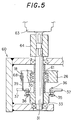
- Fig. 5 illustrates a vertical section view of the embodiment shown in Fig. 3 which is taken along line D - D thereof.
- Moving means 30 are symmetrically arranged at left and right side of the machine center line so that a necessary number of spacers 37 are inserted in each top portion of pins 40 which are arranged in a longitudinal direction of the pressure providing member 25 for setting the upper tool length to be applied a fluid pressure and said moving means 30 consists of a pair of sprockets 33,34, a pair of endless chains 35 stretched between sprocket 33, 34 to travel in the opposite directions to each other in a horizontal plane of the holder 11 interior side a plurality of spacers 37 mounted by using a link pin of the endless chain 35 and a chain driving motor 63.
- Endless chains 35, 35 travel in opposite direction with each other in respect of the machine center line 80 and are driven toward the positive direction to orderly move the spacer 37 from a refuge position of the holder rearward side to left and right clearances 48 along the tool length from the machine center line , while are driven toward reverse direction to orderly pick up the spacer 37 from the clearance 48.
- Fig. 3 and Fig. 4 respectively illustrate embodiments that spacers 37, 37 are inserted in upper surface of respective heads 41 of six pins 40 from the third to the fifth pins of left and right side from the machine center line 80.
- a diameter of the pin lower surface is set to be 15mm , it is possible to adjust the upper tool length of 225 ⁇ 15mm.
- An oblique surface 38 is formed on a front edge of the head spacer 37 (see Fig. 4), thereby the spacer can travel through the clearance 48 without contacting with the pin head and is inserted into the pin head 41 upper surface.
- All spacers 37 are inserted in the pin upper surface by driving the chain 35 to achieve a bending process of full machine width (4000mm for example) at the maximum. While all spacer 37 are set at the refuge position by driving the chain 35 to the reverse direction , thereby a bending process of an effect tool length of 100mm at minimum is achieved by four base pins 40a, 40a. 40b, 40b.
- the endless chain 35 is stretched between sprockets 33, 34 respectively mounted on a driving shaft 31 and a following shaft 32 and is actuated by an operation of a numerical control system or the like corresponding to the number of spacers 37 to be inserted.
- the driving shaft 31 includes a spacer ring 62 and a pulley 26 under the sprocket 33 and which end is provided with a coupling 64 to connect with a reduction mechanism provided motor 63 directly. Furthermore the driving shaft 31 is supported by a box 60 he holder outside(as shown by Fig. 5).
- an upper tool length indicator means 17 is mounted to cooperate with the moving means 30.
- the indicator means 17 of the upper tool length consists of an attachment 39 mounted on each chain 35, a pair of indicator bands 18 of which one end is connected with an attachment 39 to indicate the travel of the spacer 37 synchronizing with the travel of the chain 35.
- a groove 66 formed over full length of the front surface width of the holder 11 for containing the indicator band 18, pulleys 26, 28 to wind the band 18 at the lateral side of the holder 11 and a transparent scale 19 mounted on the front surface of the container groove 66 enable of viewing the travel distance the band 18 corresponding to the upper tool length to be pressurized the uniform fluid pressure by the travel of the spacer 37 (as shown by Fig. 1, Fig. 2, Fig. 3 and Fig. 5).
- the indicator band 18 is provided for indicating the upper tool length pressurized a uniform fluid pressure by the travel of the spacer 37 by driving each endless chain 35.
- the indicator band 18 is stretched between the pulley 26 mounted on the driving shaft 31 and a pulley 28 of the vertical shaft 27 mounted in front of the driving shaft 31.
- the pulley 26 is mounted on the driving shaft 31 via a ball bearing 61
- the pulley 28 of the vertical shaft 27 is also supported by the ball bearing (not shown) and travels synchronizing with the movement of the attachment 39 mounted on the chain.
- the rear end of the band 18 is fixed on the attachment 39 of the chain 35 and the forward end side thereof to be wound and guided by the pulley 26, 28 is inserted into the band container groove 66.
- the transparent scale 19 is mounted on the front surface of the band container groove 66 to view the indicator band 18 therethrough.
- a base plate 65 is fixed on the center portion of the longitudinal direction of the band container groove 66 to indicate the minimum upper tool length (1min), the front surface of the indicator band 18 inserted in the band container groove 66 is colored the same color of the base plate 65 ( white color for example) and at least vertical wall 67 of the band container groove is colored in an opposite color or in a different color density with the base plate.
- the band travels in the band container groove synchronizing with controlling the number of spacers 37 to be inserted so that the distance between both ends of the indicator band 18, 18 means an effect upper tool length from the minimum upper tool length (1 min ) to the maximum upper tool length (1 max), and said length can be read through the transparent scale 19 from outside.
- the machine center line 80 and a center line of the work sheet is adjusted by a centering device (not shown) to set the edge bending length by a back gauge.
- every eight spacers 37 are inserted in each pin 40 upper portion by actuating the driving sprocket 33 to travel the chain 35 and the necessary upper tool length of 475mm for short side pressure is adjusted so as to be 19 pitches x 25mm in associate with each space length of pins 40a, 40b adjacent to left and right side of the machine center line 80 .
- the traveling distance of the indicator band 18 is checked via the transparent scale 19 in front of the machine. Thereafter one edge of the short side is bent by pressing down the ram and the other edge of the short side is bent by a rotation of 180 ° of the work sheet 70.
- the bending angle is determined by three points of shoulder portions 57, 58 of the lower tool and height adjustable top surface 59 of the lower tool bottom member 54 to bend the work sheet 70 in a condition that the uniform fluid pressure is provided to the die in process by an operation of main cylinders 16. 16.
- the work sheet is turned 90° in a horizontal surface for centering the long side of the work sheet, thereafter every fourteen spacers 37 are inserted in left and right side by driving the driving sprocket 33 and the necessary upper tool length of 725mm for bending the edge of the long side is adjusted so as to be 29 pitches x 25mm in associate with each space length of pins 40a, 40b adjacent to left and right side of the machine center line 80.
- the necessary upper tool length of 725mm for bending the edge of the long side is adjusted so as to be 29 pitches x 25mm in associate with each space length of pins 40a, 40b adjacent to left and right side of the machine center line 80.
- an effect upper tool length can be changed automatically in according to the bending length of the work sheet without distinction of upper tool constructions such as a single and uniform upper tool for a full length of the machine width or a combination of split upper tools , thereby it is possible to achieve an efficient bending work for various length work sheet with preventing unequal bending.
- spacers which is a supplemental pressure transmission member are merely inserted orderly in the upper surface of pin line at the selected position from the machine center line among pressure transmission pins mounted between the pressure providing member and the upper tool, thereby the distance of the width direction of the upper tool line to be transmitted the pressurized force (effect length of upper tool) from the pressure providing member can be optionally set.
- an effective length of the tool which are arranged at left and right side of the press machine center line can be selected freely, corresponding to the different width of long and short edge side of the work sheet, a free selecting possibility of the tool in preventing a disproportional load thereon is increased to bend the work sheet at the press brake center line , thereby a labor saving for attaching and detaching of tool s and an automatic bending work can be achieved. Furthermore a speedy exchanging of tools and a labor saving therefor can be achieved.
Landscapes
- Engineering & Computer Science (AREA)
- Mechanical Engineering (AREA)
- Bending Of Plates, Rods, And Pipes (AREA)
Applications Claiming Priority (2)
| Application Number | Priority Date | Filing Date | Title |
|---|---|---|---|
| JP31411496 | 1996-11-12 | ||
| JP314114/96 | 1996-11-12 |
Publications (1)
| Publication Number | Publication Date |
|---|---|
| EP0841106A1 true EP0841106A1 (fr) | 1998-05-13 |
Family
ID=18049420
Family Applications (1)
| Application Number | Title | Priority Date | Filing Date |
|---|---|---|---|
| EP97630025A Ceased EP0841106A1 (fr) | 1996-11-12 | 1997-05-06 | Presse plieuse |
Country Status (3)
| Country | Link |
|---|---|
| US (1) | US5813273A (fr) |
| EP (1) | EP0841106A1 (fr) |
| KR (1) | KR100315383B1 (fr) |
Families Citing this family (4)
| Publication number | Priority date | Publication date | Assignee | Title |
|---|---|---|---|---|
| CA2360301A1 (fr) | 2001-10-26 | 2003-04-26 | Shearpress Sales Inc. | Appareil et methode de compensation des deviations angulaires d'une piece a ouvrer |
| FR2942981B1 (fr) * | 2009-03-13 | 2011-04-08 | Amada Europe | Presse plieuse pour le pliage de feuilles |
| CN107377817B (zh) * | 2017-09-07 | 2023-03-14 | 河北骄阳焊工有限公司 | 焊机用拉网折弯机及拉网折弯方法 |
| KR102243089B1 (ko) * | 2020-09-29 | 2021-04-21 | 주식회사 대성 | 절곡장치 |
Citations (4)
| Publication number | Priority date | Publication date | Assignee | Title |
|---|---|---|---|---|
| FR2179958A1 (en) * | 1972-04-13 | 1973-11-23 | Haemmerle Ag Maschf | Sheet metal working tool - with shock absorbing mounting to reduce tool damage |
| EP0237800A1 (fr) * | 1986-03-21 | 1987-09-23 | Fritz Hakemann | Presse plieuse pour plier à matrice, en particulier des tôles |
| EP0251287A1 (fr) * | 1986-06-30 | 1988-01-07 | Maru Kikai Kogyo Co., Ltd. | Dispositif pour le changement d'outil de presse à plier |
| JPH04210821A (ja) * | 1990-12-13 | 1992-07-31 | Maru Kikai Kogyo Kk | 折曲機の金型逃し装置 |
Family Cites Families (8)
| Publication number | Priority date | Publication date | Assignee | Title |
|---|---|---|---|---|
| AT283851B (de) * | 1969-02-18 | 1970-08-25 | Haemmerle Ag Maschf | Arbeitstisch an Blechbearbeitungsmaschinen |
| JPH0688079B2 (ja) * | 1986-03-25 | 1994-11-09 | 株式会社アマダ | プレスブレーキにおけるクラウニング装置 |
| US5067340A (en) * | 1988-05-05 | 1991-11-26 | Macgregor Donald C | Precision press brake |
| JPH0246922A (ja) * | 1988-08-04 | 1990-02-16 | Hisao Yamashina | ブレーキプレスにおける中ダレ防止装置 |
| US4894015A (en) * | 1988-08-31 | 1990-01-16 | Delco Electronics Corporation | Flexible circuit interconnector and method of assembly thereof |
| AT392023B (de) * | 1988-11-21 | 1991-01-10 | Haemmerle Ag | Verfahren zum biegen von blechstuecken |
| NL8901560A (nl) * | 1989-06-21 | 1991-01-16 | Wila Maschf Bv | Kantpers en een automatische bombeerinrichting daarvoor. |
| US5009098A (en) * | 1989-11-27 | 1991-04-23 | Machinefabriek Wila B.V. | Press and curve-forming means therefor |
-
1997
- 1997-05-06 EP EP97630025A patent/EP0841106A1/fr not_active Ceased
- 1997-05-30 US US08/866,182 patent/US5813273A/en not_active Expired - Fee Related
- 1997-07-02 KR KR1019970030601A patent/KR100315383B1/ko not_active Expired - Fee Related
Patent Citations (4)
| Publication number | Priority date | Publication date | Assignee | Title |
|---|---|---|---|---|
| FR2179958A1 (en) * | 1972-04-13 | 1973-11-23 | Haemmerle Ag Maschf | Sheet metal working tool - with shock absorbing mounting to reduce tool damage |
| EP0237800A1 (fr) * | 1986-03-21 | 1987-09-23 | Fritz Hakemann | Presse plieuse pour plier à matrice, en particulier des tôles |
| EP0251287A1 (fr) * | 1986-06-30 | 1988-01-07 | Maru Kikai Kogyo Co., Ltd. | Dispositif pour le changement d'outil de presse à plier |
| JPH04210821A (ja) * | 1990-12-13 | 1992-07-31 | Maru Kikai Kogyo Kk | 折曲機の金型逃し装置 |
Non-Patent Citations (1)
| Title |
|---|
| PATENT ABSTRACTS OF JAPAN vol. 16, no. 557 (M - 1340) 27 November 1992 (1992-11-27) * |
Also Published As
| Publication number | Publication date |
|---|---|
| KR100315383B1 (ko) | 2002-03-08 |
| KR19980041780A (ko) | 1998-08-17 |
| US5813273A (en) | 1998-09-29 |
Similar Documents
| Publication | Publication Date | Title |
|---|---|---|
| US4660402A (en) | Apparatus for adjusting tool length of bending machine | |
| CA1098770A (fr) | Presse-transfert | |
| EP0530375A1 (fr) | Systeme pour travailler de la matiere en plaque | |
| EP0838278A1 (fr) | Dispositif d'échange d'outil pour une presse de formage et presse de formage comprenant un tel dispositif | |
| EP0976470B1 (fr) | Machine pour le poinçonnage et pliage de tôles | |
| EP0310145B1 (fr) | Machine à cintrer | |
| US5720197A (en) | Crimper assembly | |
| JP2739104B2 (ja) | プレス加工装置 | |
| EP0841106A1 (fr) | Presse plieuse | |
| CN113290370A (zh) | 一种销钉自动压装设备 | |
| US5327760A (en) | Roller leveller | |
| JP2861768B2 (ja) | プレスの型交換装置 | |
| JP3223846B2 (ja) | プレスブレーキ | |
| IT8149917A1 (it) | Apparecchio di taglio e tranciatura di materiali in foglio in particolare lamiere metalliche | |
| WO1996029167A3 (fr) | Procede et machine de mise en place d'inserts | |
| US4745788A (en) | Roll rearranging apparatus | |
| CA2243453C (fr) | Sertisseuse | |
| CA1292422C (fr) | Monture d'outil superieur pour machine de matricage ou ses analogues | |
| JP2001025934A (ja) | ダイアッセンブリ取付機構 | |
| US5778719A (en) | Method of stretch-forming a channel material | |
| JP2551423B2 (ja) | 電線接続用スリ−ブの自動圧縮装置 | |
| JPH0741349B2 (ja) | 多段ホーマー及びその段取り替え方法 | |
| JP2870737B2 (ja) | ダイス交換装置 | |
| JP2543441B2 (ja) | 折曲機の金型逃し装置 | |
| JP2000351028A (ja) | パンチプレス |
Legal Events
| Date | Code | Title | Description |
|---|---|---|---|
| PUAI | Public reference made under article 153(3) epc to a published international application that has entered the european phase |
Free format text: ORIGINAL CODE: 0009012 |
|
| 17P | Request for examination filed |
Effective date: 19980211 |
|
| AK | Designated contracting states |
Kind code of ref document: A1 Designated state(s): CH DE FR GB IT LI |
|
| AKX | Designation fees paid |
Free format text: CH DE FR GB IT LI |
|
| RBV | Designated contracting states (corrected) |
Designated state(s): CH DE FR GB IT LI |
|
| RAP1 | Party data changed (applicant data changed or rights of an application transferred) |
Owner name: MURATA KIKAI KABUSHIKI KAISHA |
|
| 17Q | First examination report despatched |
Effective date: 20010130 |
|
| GRAG | Despatch of communication of intention to grant |
Free format text: ORIGINAL CODE: EPIDOS AGRA |
|
| STAA | Information on the status of an ep patent application or granted ep patent |
Free format text: STATUS: THE APPLICATION HAS BEEN REFUSED |
|
| 18R | Application refused |
Effective date: 20020613 |