EP0371076B1 - Systeme de distribution d'un adhesif sans fil electrique - Google Patents
Systeme de distribution d'un adhesif sans fil electrique Download PDFInfo
- Publication number
- EP0371076B1 EP0371076B1 EP88908093A EP88908093A EP0371076B1 EP 0371076 B1 EP0371076 B1 EP 0371076B1 EP 88908093 A EP88908093 A EP 88908093A EP 88908093 A EP88908093 A EP 88908093A EP 0371076 B1 EP0371076 B1 EP 0371076B1
- Authority
- EP
- European Patent Office
- Prior art keywords
- base
- gun
- electrical
- dispensing gun
- dispensing
- Prior art date
- Legal status (The legal status is an assumption and is not a legal conclusion. Google has not performed a legal analysis and makes no representation as to the accuracy of the status listed.)
- Expired
Links
- 239000000853 adhesive Substances 0.000 title abstract description 11
- 230000001070 adhesive effect Effects 0.000 title abstract description 11
- NJPPVKZQTLUDBO-UHFFFAOYSA-N novaluron Chemical compound C1=C(Cl)C(OC(F)(F)C(OC(F)(F)F)F)=CC=C1NC(=O)NC(=O)C1=C(F)C=CC=C1F NJPPVKZQTLUDBO-UHFFFAOYSA-N 0.000 claims description 12
- 239000012815 thermoplastic material Substances 0.000 claims description 12
- 239000012943 hotmelt Substances 0.000 claims description 6
- 230000000295 complement effect Effects 0.000 claims description 5
- 229920001169 thermoplastic Polymers 0.000 claims description 5
- 239000004416 thermosoftening plastic Substances 0.000 claims description 5
- 238000010438 heat treatment Methods 0.000 claims description 4
- 230000000694 effects Effects 0.000 abstract description 6
- 239000007787 solid Substances 0.000 abstract description 3
- 239000000155 melt Substances 0.000 abstract 1
- 239000003292 glue Substances 0.000 description 38
- 239000000463 material Substances 0.000 description 8
- 238000005192 partition Methods 0.000 description 5
- 239000004831 Hot glue Substances 0.000 description 2
- 238000010586 diagram Methods 0.000 description 1
- 230000005611 electricity Effects 0.000 description 1
- 238000007373 indentation Methods 0.000 description 1
- 239000012768 molten material Substances 0.000 description 1
- 229910052754 neon Inorganic materials 0.000 description 1
- GKAOGPIIYCISHV-UHFFFAOYSA-N neon atom Chemical compound [Ne] GKAOGPIIYCISHV-UHFFFAOYSA-N 0.000 description 1
- 239000004033 plastic Substances 0.000 description 1
Images


Classifications
-
- B—PERFORMING OPERATIONS; TRANSPORTING
- B25—HAND TOOLS; PORTABLE POWER-DRIVEN TOOLS; MANIPULATORS
- B25H—WORKSHOP EQUIPMENT, e.g. FOR MARKING-OUT WORK; STORAGE MEANS FOR WORKSHOPS
- B25H3/00—Storage means or arrangements for workshops facilitating access to, or handling of, work tools or instruments
- B25H3/006—Storage means specially adapted for one specific hand apparatus, e.g. an electric drill
-
- B—PERFORMING OPERATIONS; TRANSPORTING
- B05—SPRAYING OR ATOMISING IN GENERAL; APPLYING FLUENT MATERIALS TO SURFACES, IN GENERAL
- B05C—APPARATUS FOR APPLYING FLUENT MATERIALS TO SURFACES, IN GENERAL
- B05C17/00—Hand tools or apparatus using hand held tools, for applying liquids or other fluent materials to, for spreading applied liquids or other fluent materials on, or for partially removing applied liquids or other fluent materials from, surfaces
- B05C17/005—Hand tools or apparatus using hand held tools, for applying liquids or other fluent materials to, for spreading applied liquids or other fluent materials on, or for partially removing applied liquids or other fluent materials from, surfaces for discharging material from a reservoir or container located in or on the hand tool through an outlet orifice by pressure without using surface contacting members like pads or brushes
- B05C17/00523—Hand tools or apparatus using hand held tools, for applying liquids or other fluent materials to, for spreading applied liquids or other fluent materials on, or for partially removing applied liquids or other fluent materials from, surfaces for discharging material from a reservoir or container located in or on the hand tool through an outlet orifice by pressure without using surface contacting members like pads or brushes provided with means to heat the material
Definitions
- This invention relates to a thermoplastic dispensing system.
- US-A-4 333 623 discloses a thermoplastic dispensing system including a hot-melt dispensing gun having a body portion containing an electrical heater, a nozzle for dispensing heated thermoplastic material, a handle portion for manual manipulation of the dispensing gun by an operator, and an entry port for accepting a supply of thermoplastic material for heating by the heater and dispensing from the nozzle, end a base upon which the dispensing gun is mountable and dismountable.
- the electrical heater is powered through an electrical power cord which passes through the handle and is connected to an electrical outlet in the usual manner.
- the material to be dispensed for example, hot-melt adhesive in solid stick form, is loaded into the gun through the entry port, melted by the heater, and dispensed through a nozzle.
- a trigger is provided to selectively control the velocity and volume of the heated material dispensed through the nozzle.
- the ability to manually place the nozzle against or adjacent to the area onto which the adhesive is to be dispensed can be hindered by the electrical power cord. For example, the cord can become entangled or snagged on the work table and thus limit the usefulness of the dispenser.
- the present invention provides a thermoplastic dispensing system including a hot-melt dispensing gun having a body portion containing an electrical heater, a nozzle for dispensing heated thermoplastic material, a handle portion for manual manipulation of the dispensing gun by an operator, and an entry port for accepting a supply of thermoplastic material for heating by the heater and dispensing from the nozzle and a base upon which the dispensing gun is mountable and dismountable, characterized in that the hot-melt dispensing gun is cordless, and the base is provided with mechanical and electrical interface means for connecting the handle portion to the base during mounting, said interface means including a first tab on the handle portion and a second tab on the base, the first and second tabs interengaging with one another to control the dispensing gun to pivot about the first and second interengaged tabs during mounting and dismounting of the handle portion to and from the base.
- each of the first and second tabs has a respective curvilinear surface for mutual interengagement during mounting and dismounting of the dispensing gun.
- the radius of each respective curvilinear surface for the first and second tabs is substantially equal.
- the interface means further comprises switching means for closing an electrical supply circuit when the dispensing gun is mounted on the base and for opening the electrical supply circuit when the dispensing gun is dismounted from the base.
- the interface means comprises a key for actuating the switching means for closing the electrical supply circuit when the dispensing gun is mounted to the base.
- the switching means is normally biased to an open position for opening the electrical supply circuit when the dispensing gun is dismounted from the base.
- the electrical supply circuit includes light emitting means (LED) that is illuminated when the switching means is closed.
- LED light emitting means
- the interface means comprises at least two electrical contacts of a first type on the handle portion for engaging complementary electrical contacts of a second type on the base, the electrical contacts of the first type engaging respective ones of the second type on mounting of the dispensing gun.
- the complementary first type and second type electrical contacts are mounted in a staggered relationship relative to one another.
- the base comprises a front pedestal having a frontwardly positioned well for accumulating excess thermoplastic material exiting from the forward portion of the dispensing gun when the dispensing gun is mounted on the base.
- the base comprises a rear pedestal upon which the interface means is mounted.
- the interface means is positioned atop the rear pedestal.
- the base includes front and rear portions and an intermediate portion connected therebetween having a cavity formed therein for receiving a supply of thermoplastic material.
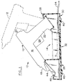
- FIG. 1 A preferred embodiment of a cordless adhesive dispensing system in accordance with the present invention is shown in FIG. 1 and designated generally therein by the reference character 10.
- the system 10 includes an adhesive dispensing gun, referred to herein as glue gun 12, and a glue gun base 14 to which the glue gun 12 is mounted to and dismounted from by the user.
- the glue gun 12 includes a body portion 16 and a nozzle 18 at its forward end from which heated, molten material, including various types of adhesives and caulking, is discharged.
- An entry port 20 is provided at the opposite end of the body 16 and receives pre-formed sticks (not shown) of solid hot-melt material for heating in the glue gun 12 and eventual discharge through the nozzle 18.
- the sticks are formed in lengths of 5.1 cm.
- a handle 22 is attached to the glue gun body 16 and includes a user-operable trigger 24 which is squeezed to discharge the hot, plastic material from the nozzle 18 in the conventional manner.
- a suitable gun glue 12 modified in accordance with the present invention is the Model 9735 Type 2 gun sold by Black & Decker, Hunt Valley, Maryland 21030, U.S.A.
- the glue gun base 14 which is shown in cross-section in FIG. 1 and in perspective view in FIG. 2, includes a forward portion 26 (on the left in FIG. 1), a rear portion 30 at the opposite end, and an intermediate portion 32.
- An electrical power cord 34 (FIG. 1) is connected to the rear portion 30 of the base 14 to supply electrical power to the glue gun 12 as described more fully below in relationship to FIG. 9.
- the base 14 includes (FIG. 2) laterally outward extending portions 36 and 38 that extend along the length of the base 14.
- Support pads or feet 40 (FIG. 1) are attached to or formed as part of the underside of the laterally outward extending portions 36 and 38.
- a pedestal 42 and upstanding sidewalls 44 and 46 are formed at the forward end of the base 14 and define a forwardly facing well 48 for receiving any adhesive material dropped from the nozzle 18 when the glue gun 12 is mounted to the base 14.
- An indentation 50 shown in detail in FIG. 3, is formed in the upwardly facing surface of the pedestal 42 and engages the forward end of the glue gun 12 when it is mounted on the base 14 as shown in FIG. 1.
- the intermediate portion 32 of the base 14 includes sidewalls 52 and 54 that define an interior well 56 for storing pre-formed adhesive sticks S (shown in dotted line in FIG. 1) for loading into the glue gun 12 through the entry port 20.
- the rear portion 30 of the base 14 includes an upstanding pedestal 58 defined by a top surface 60 and a forwardly inclined surface 62.
- a connection interface is formed on the inclined surface 62 for mechanically and electrically engaging the handle 22 of the glue gun 12 as shown in FIG. 1.
- the lower portion of the glue gun handle 22 includes a depending skirt 70 that cooperates with an interior partition 72 to define a connection cavity 74.
- Blade-type electrical contacts 76 and 78 depend from the partition 72 for electrically engaging the connection interface 64 as described below.
- the blade-type contacts 76 and 78 are staggered relative to one another, that is, they are mounted in a non co-planar relationship to prevent direct connection to the end of a conventional electric extension cord.
- a tab 80 is formed on the rear side of the handle 22 and merges at its upper end with a curved pivot surface 82 that is formed at a preferred radius R.
- a vertically aligned key 84 is formed on the forwardly facing side of the handle 22 and serves to both assist in aligning the glue gun 12 when it is mounted to the base 14 as well as actuating an electrical switch as described below.
- connection interface 64 of FIG. 2 is shown in greater detail in FIGS. 6 and 7.
- a connection cavity 90 is formed in the forwardly inclined surface 62 of the pedestal 58 (FIG. 2) and is defined by a generally ovoid interior wall 92 and a cooperating interior partition 94.
- a connector block 96 extends upwardly from the interior partition 94 and includes slot-like openings 98 and 100 for receiving the blade contacts 76 and 78, respectively, of the glue gun 12 (FIGS. 4 and 5).
- the connector block 96 is dimensioned to define an annular groove 102 with the interior wall 92.
- the annular groove 102 receives the depending skirt 70 of the handle 22 as shown in broken-line illustration in FIG. 7.
- a keyway 104 is formed at the forward side of the interior wall 92 for accepting the key 84 on the forward side of the handle 22.
- a tab 106 extends forwardly from the rear side of the interior wall 92 and, as shown in FIG. 7, overhangs the wall 92 and is spaced from the interior partition 94 by a distance at least coextensive with the length of the tab 80 extending from the rear side of the handle 22.
- the forward end of the tab 106 is formed at a radius substantially the same as the radius R of the pivot surface 82 formed on the handle 22 above the tab 80.
- Electrical receptacle contacts 108 and 110 are mounted in the connector block 96 and are designed to receive and effect electrical contact with the blade contacts 76 and 78, respectively, as they pass through the slots 98 and 100.
- a normally OFF, spring-biased, single-pole switch 112 forms part of the connection interface 64 and includes an actuatable member 114 that is normally biased by an internal spring (not shown) to a first position 114′ and extends into the lower portion of the keyway 104.
- the member 114 is forced to a second, ON position (as indicated in solid-line illustration in FIG. 7) by the key 84 as the handle 22 is inserted into the interface 64.
- connection interface 64 functions to allow the user to effect mechanical and electrical engagement and disengagement of the glue gun 12 with its base 14 with a convenient pivoting motion.
- the handle 22 of the glue gun 12 is engaged with the connection interface 64 by first inserting the tab 80 of the handle 22 into the cavity 90 and beneath the overhanging tab 106 with the pivot surface 82 of the handle 22 contacting the similarly radiused surface at the end of the tab 106.
- the glue gun 12 is rotated counterclockwise in FIG. 8 with the pivot surface 82 sliding relative to the radiused tab 106 to allow the skirt 70 to enter the annular groove 102 of the connection interface 64 with the key 84 entering the keyway 104.
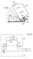
- FIG. 9 An exemplary electrical circuit for the system 10 is shown in FIG. 9 and, as shown, a heater element H is mounted in the glue gun 12 and is connected in parallel circuit with a series-connected light-emitting diode LED, neon lamp, or other suitable light-emitting devices, and current-limiting resistor R1 with electrical connection to the base 14 made through the contact pairs 76/108 and 78/110.
- the switch 112 When the switch 112 is closed, electrical current flows through the heater H to heat the thermoplastic adhesive with the light emitting diode LED also illuminated to indicate current flow to the user.
- the light emitting diode LED can be mounted at any location of the glue gun 12, although a rearward position on the handle 22 is preferred.
- the glue gun 12 is mounted to the base 14 with the heater H operative to melt the thermoplastic material in the gun.
- the user grasps the handle 22 and pivots the glue gun 12 clockwise in FIG. 1 to the dotted-line position to interrupt the flow of electricity by allowing the switch 112 to move to its normally open position, to disconnect the electrical contact pairs 76/108 and 78/110, and to cause the tab 80 on the handle 22 to clear the tab 106 and thus allow the user to lift the glue gun 12 from the base 14 for use.
- the heated components of the glue gun 12, principally the heater H and the reserve of molten thermoplastic material have sufficient heat capacity to provide enough heated material for the range of expected applications. After the heated material is applied, the glue gun 12 is returned to the base 14 in the manner described above.
- the present invention advantageously provides a hand-held, cordless glue gun system in which the gun is conveniently mounted to and dismounted from a support base to provide a convenient dispensing system compared to prior glue guns which are permanently attached to a power source through a line cord.
Landscapes
- Engineering & Computer Science (AREA)
- Mechanical Engineering (AREA)
- Coating Apparatus (AREA)
Abstract
Claims (13)
- Système de distribution d'une matière thermoplastique, comprenant un pistolet (12) de distribution d'une matière fondant à chaud qui comporte un corps (16) contenant un élément chauffant électrique, un ajutage (18) de distribution de la matière thermoplastique chauffée, une poignée (22) de manipulation à la main du pistolet de distribution (12) par un utilisateur, et un trou d'entrée (20) destiné à admettre une réserve de matière thermoplastique destinée à être chauffée par l'élément chauffant et distribuée par l'ajutage (18), ainsi qu'un support (14) sur lequel le pistolet distributeur (12) peut être mis et pris, caractérisé en ce que le pistolet (12) de distribution de la matière fondant à chaud est sans cordon et le support (14) est équipé d'un moyen (64) formant une interface mécanique et électrique pour la jonction de la poignée (22) et du support (14) pendant la mise en place du pistolet sur ce dernier, ledit moyen (64) formant une interface comprenant une première patte (80) située sur la poignée (22) et une seconde patte (106) située sur le support (14), les première et seconde pattes (80, 106) s'enclenchant l'une sur l'autre pour régler le pivotement du pistolet distributeur (12) autour des première et seconde pattes enclenchées l'une sur l'autre (80, 106) pendant la mise en place et l'enlèvement de la poignée (22) sur et du support (14).
- Système selon la revendication 1, caractérisé en ce que chacune desdites première et seconde pattes (80, 106) présente une surface courbe respective d'enclenchement mutuel pendant la mise en place et l'enlèvement du pistolet distributeur (12).
- Système selon la revendication 2, caractérisé en ce que le rayon de chaque surface courbe respective des première et seconde pattes (80, 106) est sensiblement égal.
- Système selon la revendication 1, 2 ou 3, caractérisé en ce que ledit moyen (64) formant une interface comprend par ailleurs un moyen de commutation (112) destiné à fermer un circuit électrique d'alimentation lorsque le pistolet distributeur (12) est placé sur le support (14) et pour ouvrir le circuit électrique d'alimentation lorsque le pistolet distributeur (12) est enlevé du support (14).
- Système selon la revendication 4, caractérisé en ce que le moyen (64) formant une interface comprend une clavette (84) d'actionnement du moyen de commutation (112) pour fermer le circuit électrique d'alimentation lorsque le pistolet distributeur (12) est placé sur le support (14).
- Système selon la revendication 4 ou 5, caractérisé en ce que le moyen de commutation (112) est normalement repoussé à une position d'ouverture afin d'ouvrir le circuit électrique d'alimentation lorsque le pistolet distributeur (12) est enlevé du support (14).
- Système selon la revendication 4, 5 ou 6, caractérisé en ce que le circuit électrique d'alimentation comprend un moyen électro-luminescent (LED) qui s'allume lorsque le moyen de commutation (112) est fermé.
- Système selon l'une quelconque des revendications précédentes, caractérisé en ce que le moyen (64) formant une interface comprend au moins deux contacts électriques d'un premier type (76, 78) placés sur la poignée (22) et destinés à entrer en prise avec des contacts électriques complémentaires d'un second type (108, 110) situés sur le support (14), les contacts électriques du premier type (76, 78) entrant en prise avec l'un, respectif, de chacun des contacts du second type (108, 110) lorsque le pistolet distributeur (12) est mis en place.
- Système selon la revendication 8, caractérisé en ce que les contacts électriques complémentaires du premier type (76, 78) et du second type (108, 110) sont montés de manière à être décalés l'un par rapport à l'autre.
- Système selon l'une des revendications précédentes, caractérisé en ce que le support (14) comprend un appui antérieur (42) comportant une cuvette (48) tournée vers l'avant et destinée à collecter l'excès de matière thermoplastique sortant de la partie antérieure du pistolet distributeur (12) lorsque le pistolet distributeur (12) est placé sur le support (14).
- Système selon l'une quelconque des revendications précédentes, caractérisé en ce que le support (14) comprend un appui arrière (58) sur lequel le moyen (64) formant une interface est disposé.
- Système selon la revendication 11, caractérisé en ce que le moyen (64) formant une interface est placé au sommet de l'appui arrière (58).
- Système selon l'une quelconque des revendications précédentes, caractérisé en ce que le support (14) comprend des parties antérieure (26) et arrière (30) et une partie intermédiaire (32) reliant les deux précédentes et dans laquelle est formée une cavité (56) de logement d'une réserve de matière thermoplastique.
Applications Claiming Priority (2)
| Application Number | Priority Date | Filing Date | Title |
|---|---|---|---|
| US82473 | 1987-08-07 | ||
| US07/082,473 US4826049A (en) | 1987-08-07 | 1987-08-07 | Cordless adhesive dispensing system |
Publications (2)
| Publication Number | Publication Date |
|---|---|
| EP0371076A1 EP0371076A1 (fr) | 1990-06-06 |
| EP0371076B1 true EP0371076B1 (fr) | 1992-11-11 |
Family
ID=22171441
Family Applications (1)
| Application Number | Title | Priority Date | Filing Date |
|---|---|---|---|
| EP88908093A Expired EP0371076B1 (fr) | 1987-08-07 | 1988-08-04 | Systeme de distribution d'un adhesif sans fil electrique |
Country Status (4)
| Country | Link |
|---|---|
| US (1) | US4826049A (fr) |
| EP (1) | EP0371076B1 (fr) |
| DE (1) | DE3875974T2 (fr) |
| WO (1) | WO1989001367A1 (fr) |
Cited By (1)
| Publication number | Priority date | Publication date | Assignee | Title |
|---|---|---|---|---|
| US20230344057A1 (en) * | 2019-08-08 | 2023-10-26 | Black & Decker Inc. | Power tools and power tools platform |
Families Citing this family (44)
| Publication number | Priority date | Publication date | Assignee | Title |
|---|---|---|---|---|
| USD315283S (en) | 1988-06-13 | 1991-03-12 | The Stanley Works | Combined cordless glue gun stand and power base therefor |
| EP0423388A1 (fr) * | 1989-10-18 | 1991-04-24 | STEINEL Entwicklungs-GmbH für Elektrotechnik und Elektronik | Pistolet à colle chauffé électriquement |
| US4998698A (en) * | 1989-12-29 | 1991-03-12 | Martinson Jon P | Glue gun holder apparatus |
| US5688421A (en) * | 1991-10-11 | 1997-11-18 | Walton; William M. | Dispenser for heat-liquefiable material with contiguous PTC heater and heat exchanging member |
| IT226715Z2 (it) * | 1992-06-24 | 1997-07-01 | Dassi Francesco | Pulitore e disinfestatore per stanze da bagno e servizi igienici |
| US5236269A (en) * | 1993-01-14 | 1993-08-17 | Mattel, Inc. | Battery-powered dispenser for hot melt adhesive |
| US5429331A (en) * | 1993-12-10 | 1995-07-04 | Massena; Len | Glue gun holder |
| US5664701A (en) * | 1995-01-25 | 1997-09-09 | Uniplast, Inc. | Glue gun system with removable cartridges |
| FR2739266B1 (fr) * | 1995-10-03 | 1997-12-19 | Seb Sa | Ensemble applicateur et applicateur de produit thermofusible |
| US6041972A (en) * | 1997-01-17 | 2000-03-28 | Maayeh; George | Warming tray for holding removable cartridges |
| US5881924A (en) * | 1997-01-17 | 1999-03-16 | Uniplast, Inc. | Feeder handler for a hot glue gun |
| US5881912A (en) * | 1997-01-17 | 1999-03-16 | Uniplast, Inc. | Glue gun with removable barrel |
| US6359613B1 (en) * | 1998-10-07 | 2002-03-19 | Cts Corporation | Pointing stick having chip resistors |
| US6056165A (en) * | 1998-10-21 | 2000-05-02 | Speranza; James D. | Free standing cordless gun for dispensing liquid glue and similar materials |
| USD421759S (en) * | 1999-01-29 | 2000-03-21 | George Maayeh | Warming tray for glue heating cartridges |
| USD433301S (en) * | 1999-02-26 | 2000-11-07 | Carl E Pack | Hot glue gun stand |
| DE50001168D1 (de) * | 1999-03-05 | 2003-03-06 | Steinel Gmbh & Co Kg | Heizklebevorrichtung |
| US6123299A (en) * | 1999-07-01 | 2000-09-26 | Zach, Sr.; Howard L. | Electrical outlet curling iron |
| US6820768B2 (en) * | 2002-01-25 | 2004-11-23 | Adhesive Technologies, Inc. | Elongate hand held glue gun |
| US20040232289A1 (en) * | 2003-05-20 | 2004-11-25 | Roberto Aguirre | Third hand stand |
| EP1720793A4 (fr) * | 2004-02-05 | 2009-03-04 | Adhesive Technologies Inc | Distributeur de cartouches pour matieres liquides ou semi-liquides |
| US7784750B2 (en) * | 2004-07-12 | 2010-08-31 | Lori Burk | Hair dryer stand |
| US20060081650A1 (en) * | 2004-10-13 | 2006-04-20 | Hyperion Innovations, Inc. | Glue dispensing apparatus |
| US20060191957A1 (en) * | 2004-10-13 | 2006-08-31 | Hyperion Innovations Inc. | Glue dispensing apparatus |
| USD541121S1 (en) | 2004-11-18 | 2007-04-24 | Hyperion Innovations, Inc. | Liquid dispensing apparatus |
| US20060196888A1 (en) * | 2004-12-17 | 2006-09-07 | Agronin Michael L | Glue gun assembly with temperature indicator and drip reducing base |
| DE102005009913A1 (de) * | 2005-03-01 | 2006-09-07 | Robert Bosch Gmbh | Akkuhandwerkzeugmaschine mit Ladeschale |
| US20060255219A1 (en) * | 2005-05-05 | 2006-11-16 | Mr. Ming-Jeing Wang | [hair drier support rack] |
| EP1849565A1 (fr) * | 2006-04-20 | 2007-10-31 | Mobiletron Electronics Co. Ltd. | Connecteur d'un outil électrique |
| CN101791601A (zh) * | 2010-01-20 | 2010-08-04 | 常州亿晶光电科技有限公司 | 便携式热熔胶枪放置架 |
| USD642736S1 (en) | 2011-03-29 | 2011-08-02 | Easy Life Products, Inc. | Stand for a hair dryer |
| US9731317B2 (en) | 2014-10-15 | 2017-08-15 | Sonoco Development, Inc. | Device for holding and dispensing viscous material |
| DE102014118797A1 (de) * | 2014-12-17 | 2016-06-23 | Vorwerk & Co. Interholding Gesellschaft mit beschränkter Haftung | Behälter mit einer Akkumulator betriebenen Heißklebepistole sowie Heißklebepistole mit Vorwärmfunktion |
| US9643200B2 (en) * | 2014-12-19 | 2017-05-09 | Richard A. Belanger | Squeeze container liquid extrusion tool |
| CN204397850U (zh) * | 2015-01-14 | 2015-06-17 | 浙江普莱得电器有限公司 | 一种方便切换的多功能工具 |
| TWM517025U (zh) * | 2015-11-09 | 2016-02-11 | Chia-Wen Hsu | 安全熱熔膠槍 |
| CN107521744A (zh) * | 2017-09-21 | 2017-12-29 | 北京天申正祥科技有限公司 | 一种香烟条盒纸的喷胶装置及其使用方法 |
| USD989581S1 (en) * | 2021-07-29 | 2023-06-20 | Chuanlin Mao | Combined glue gun and base |
| USD1063376S1 (en) | 2022-06-08 | 2025-02-25 | Yeti Coolers, Llc | Container |
| USD1024557S1 (en) | 2022-06-08 | 2024-04-30 | Yeti Coolers, Llc | Container |
| USD1036116S1 (en) | 2022-06-08 | 2024-07-23 | Yeti Coolers, Llc | Container |
| US11912477B2 (en) | 2022-06-08 | 2024-02-27 | Yeti Coolers, Llc | Container with handle and latching system |
| US20240051110A1 (en) * | 2022-08-12 | 2024-02-15 | Techtronic Cordless Gp | Rotary Tool and Standby Base |
| USD1036119S1 (en) | 2022-11-30 | 2024-07-23 | Yeti Coolers, Llc | Container |
Family Cites Families (31)
| Publication number | Priority date | Publication date | Assignee | Title |
|---|---|---|---|---|
| US1851685A (en) * | 1929-06-07 | 1932-03-29 | John Hulting | Heating and supporting means for electric irons |
| US2750696A (en) * | 1953-11-04 | 1956-06-19 | Hoover Co | Electric flat iron and holder |
| US2820877A (en) * | 1956-08-16 | 1958-01-21 | Jr David J Oates | Cordless electric iron and stand assembly |
| US2995159A (en) * | 1957-12-23 | 1961-08-08 | United Shoe Machinery Corp | Portable plastic injection devices |
| US3183891A (en) * | 1963-05-07 | 1965-05-18 | Clyde E Macdonald | Cordless electric device and recharging stand therefor |
| US3277358A (en) * | 1963-09-09 | 1966-10-04 | Thomas H Nicholl | Battery charger |
| US3204828A (en) * | 1964-03-16 | 1965-09-07 | United Shoe Machinery Corp | Portable thermoplastic cement dispensers |
| US3359635A (en) * | 1965-01-05 | 1967-12-26 | Sunbeam Corp | Electrically operated dry shaver |
| US3388885A (en) * | 1966-02-25 | 1968-06-18 | Robertshaw Controls Co | Switch construction with quick connecting mounting bracket |
| US3398260A (en) * | 1966-08-29 | 1968-08-20 | Scovill Manufacturing Co | Cordless electric iron |
| US3413742A (en) * | 1967-09-28 | 1968-12-03 | Scovill Manufacturing Co | Combination clothes-pressing iron and rest mount therefor with automatic homing means |
| US3523176A (en) * | 1967-12-18 | 1970-08-04 | Roberts Consolidated Ind | Electric iron for heat sensitive adhesive tape for seaming carpets |
| DE2036268A1 (de) * | 1970-07-22 | 1972-01-27 | Harsanyi E | Schnurloses elektrisches Bugeleisen mit Untersatz |
| US3728664A (en) * | 1971-12-21 | 1973-04-17 | Repco Inc | Battery latching mechanism |
| US3745676A (en) * | 1972-08-04 | 1973-07-17 | J Dikoff | Cordless iron apparatus |
| US3924097A (en) * | 1973-12-17 | 1975-12-02 | Eldon Ind Inc | Stand for charging an electric tool and the combination of this stand with such a tool |
| DE2412143A1 (de) * | 1974-03-13 | 1975-09-25 | Krone Gmbh | Transportable mehrzweck-werkzeugmaschine |
| US3942856A (en) * | 1974-12-23 | 1976-03-09 | Mindheim Daniel J | Safety socket assembly |
| US4092580A (en) * | 1975-03-12 | 1978-05-30 | Prinsze Onno M | Energizer apparatus for rechargeable flashlight batteries |
| FR2306823A1 (fr) * | 1975-04-09 | 1976-11-05 | Berthollet Jean Baptiste | Dispositif pour extrusion d'une substance pateuse |
| US4101756A (en) * | 1976-03-18 | 1978-07-18 | Jiichi Yamano | Electrically heated curling iron and stand therefor |
| US4085867A (en) * | 1976-07-26 | 1978-04-25 | Peter Van Nest Heller | Dispensing containers and holder |
| US4225814A (en) * | 1978-08-11 | 1980-09-30 | Black & Decker, Inc. | Cordless vacuum cleaner storing and recharging system |
| US4333623A (en) * | 1980-03-31 | 1982-06-08 | May Walder C | Glue gun holder |
| US4418268A (en) * | 1981-01-22 | 1983-11-29 | Munshaw Harold A | Soldering iron holder with ready indicator and safety shutoff |
| US4528429A (en) * | 1984-03-02 | 1985-07-09 | Dart Industries Inc. | Electrical switch-plug assembly with baffle |
| DE3418630A1 (de) * | 1984-05-18 | 1985-11-21 | Horst 3000 Hannover Pudwill | Vorrichtung zum verpressen von dichtungsmasse oder dergleichen, insbesondere fugendichtungsmasse |
| DE3540898A1 (de) * | 1984-11-19 | 1986-05-28 | Matsushita Electric Industrial Co., Ltd., Kadoma, Osaka | Wiederaufladbare, kabellose staubsaugervorrichtung |
| DE3517830A1 (de) * | 1985-05-17 | 1986-11-20 | Geka-Werk Reinhold Klein KG, 3573 Gemünden | Anschlussgeraet fuer ein schnurloses elektrogeraet |
| US4692587A (en) * | 1986-02-19 | 1987-09-08 | Spirk Jr John W | Hand tool and support |
| US4730799A (en) * | 1987-04-28 | 1988-03-15 | Best Tool, Inc. | Glue gun organizer |
-
1987
- 1987-08-07 US US07/082,473 patent/US4826049A/en not_active Expired - Fee Related
-
1988
- 1988-08-04 DE DE8888908093T patent/DE3875974T2/de not_active Expired - Fee Related
- 1988-08-04 EP EP88908093A patent/EP0371076B1/fr not_active Expired
- 1988-08-04 WO PCT/US1988/002657 patent/WO1989001367A1/fr not_active Ceased
Cited By (4)
| Publication number | Priority date | Publication date | Assignee | Title |
|---|---|---|---|---|
| US20230344057A1 (en) * | 2019-08-08 | 2023-10-26 | Black & Decker Inc. | Power tools and power tools platform |
| US12134179B2 (en) * | 2019-08-08 | 2024-11-05 | Black & Decker Inc. | Power tools and power tools platform |
| US12202118B2 (en) | 2019-08-08 | 2025-01-21 | Black & Decker Inc. | Power tools and power tools platform |
| US12296455B2 (en) | 2019-08-08 | 2025-05-13 | Black & Decker Inc. | Power tools and power tools platform |
Also Published As
| Publication number | Publication date |
|---|---|
| US4826049A (en) | 1989-05-02 |
| DE3875974T2 (de) | 1993-04-15 |
| EP0371076A1 (fr) | 1990-06-06 |
| WO1989001367A1 (fr) | 1989-02-23 |
| DE3875974D1 (de) | 1992-12-17 |
Similar Documents
| Publication | Publication Date | Title |
|---|---|---|
| US4826049A (en) | Cordless adhesive dispensing system | |
| EP0401531B1 (fr) | Aspirateur de poussières alimenté par batterie | |
| US4064447A (en) | Cordless portable electrically powered device | |
| US4670701A (en) | Rechargeable cordless vacuum cleaner apparatus | |
| EP0466306B1 (fr) | Tondeuse à gazon | |
| CA1133052A (fr) | Systeme de rangement de recharge pour aspirateur sous cordon | |
| CA1229117A (fr) | Fer a vapeur electronique | |
| KR860002694Y1 (ko) | 휴대용 전기소제 | |
| US5208525A (en) | Electric power supply assembly for a cordless electric appliance | |
| US5136229A (en) | Power pack device | |
| US6112414A (en) | Rechargeable hair clipper assembly | |
| US4559456A (en) | Battery powered electric appliance | |
| US5390433A (en) | Pressing iron with cord swivel cord guard and lobed heel | |
| US4692587A (en) | Hand tool and support | |
| US5446262A (en) | Soldering iron and soldering iron tip with spaced heatable shell member | |
| US5881912A (en) | Glue gun with removable barrel | |
| US5881924A (en) | Feeder handler for a hot glue gun | |
| JPS59174103A (ja) | 手持ちヘヤ−ドライヤ−付き壁取り付け装置 | |
| CA1248865A (fr) | Fer a repasser de voyage | |
| US20060081650A1 (en) | Glue dispensing apparatus | |
| US5703751A (en) | Electrical apparatus with a detachable power supply base | |
| US6041972A (en) | Warming tray for holding removable cartridges | |
| CA1220128A (fr) | Fer portatif de repassage a la vapeur | |
| US12070767B2 (en) | Adhesive dispensing system | |
| US5881923A (en) | Removable cartridge for a hot glue gun |
Legal Events
| Date | Code | Title | Description |
|---|---|---|---|
| PUAI | Public reference made under article 153(3) epc to a published international application that has entered the european phase |
Free format text: ORIGINAL CODE: 0009012 |
|
| 17P | Request for examination filed |
Effective date: 19900119 |
|
| AK | Designated contracting states |
Kind code of ref document: A1 Designated state(s): DE FR GB |
|
| 17Q | First examination report despatched |
Effective date: 19920121 |
|
| GRAA | (expected) grant |
Free format text: ORIGINAL CODE: 0009210 |
|
| AK | Designated contracting states |
Kind code of ref document: B1 Designated state(s): DE FR GB |
|
| REF | Corresponds to: |
Ref document number: 3875974 Country of ref document: DE Date of ref document: 19921217 |
|
| ET | Fr: translation filed | ||
| PLBE | No opposition filed within time limit |
Free format text: ORIGINAL CODE: 0009261 |
|
| STAA | Information on the status of an ep patent application or granted ep patent |
Free format text: STATUS: NO OPPOSITION FILED WITHIN TIME LIMIT |
|
| 26N | No opposition filed | ||
| PGFP | Annual fee paid to national office [announced via postgrant information from national office to epo] |
Ref country code: GB Payment date: 20000703 Year of fee payment: 13 |
|
| PGFP | Annual fee paid to national office [announced via postgrant information from national office to epo] |
Ref country code: FR Payment date: 20000803 Year of fee payment: 13 |
|
| PGFP | Annual fee paid to national office [announced via postgrant information from national office to epo] |
Ref country code: DE Payment date: 20000830 Year of fee payment: 13 |
|
| REG | Reference to a national code |
Ref country code: GB Ref legal event code: 732E |
|
| REG | Reference to a national code |
Ref country code: FR Ref legal event code: TP |
|
| PG25 | Lapsed in a contracting state [announced via postgrant information from national office to epo] |
Ref country code: GB Free format text: LAPSE BECAUSE OF NON-PAYMENT OF DUE FEES Effective date: 20010804 |
|
| GBPC | Gb: european patent ceased through non-payment of renewal fee |
Effective date: 20010804 |
|
| PG25 | Lapsed in a contracting state [announced via postgrant information from national office to epo] |
Ref country code: FR Free format text: LAPSE BECAUSE OF NON-PAYMENT OF DUE FEES Effective date: 20020430 |
|
| PG25 | Lapsed in a contracting state [announced via postgrant information from national office to epo] |
Ref country code: DE Free format text: LAPSE BECAUSE OF NON-PAYMENT OF DUE FEES Effective date: 20020501 |
|
| REG | Reference to a national code |
Ref country code: FR Ref legal event code: ST |