EP0371182A1 - Matrixnadeldruckkopf der Klappankerbauart - Google Patents
Matrixnadeldruckkopf der Klappankerbauart Download PDFInfo
- Publication number
- EP0371182A1 EP0371182A1 EP88730265A EP88730265A EP0371182A1 EP 0371182 A1 EP0371182 A1 EP 0371182A1 EP 88730265 A EP88730265 A EP 88730265A EP 88730265 A EP88730265 A EP 88730265A EP 0371182 A1 EP0371182 A1 EP 0371182A1
- Authority
- EP
- European Patent Office
- Prior art keywords
- hinged
- pin
- needle
- electromagnetic coil
- magnet yoke
- Prior art date
- Legal status (The legal status is an assumption and is not a legal conclusion. Google has not performed a legal analysis and makes no representation as to the accuracy of the status listed.)
- Granted
Links
- 239000011159 matrix material Substances 0.000 title claims abstract description 15
- 238000005495 investment casting Methods 0.000 claims abstract description 9
- 230000004907 flux Effects 0.000 claims description 9
- 238000010276 construction Methods 0.000 abstract 1
- 238000005245 sintering Methods 0.000 abstract 1
- 238000004519 manufacturing process Methods 0.000 description 6
- 238000013016 damping Methods 0.000 description 3
- 230000007547 defect Effects 0.000 description 3
- 239000000463 material Substances 0.000 description 3
- 239000000243 solution Substances 0.000 description 3
- 241001295925 Gegenes Species 0.000 description 1
- 238000009826 distribution Methods 0.000 description 1
- 230000002349 favourable effect Effects 0.000 description 1
- 238000002347 injection Methods 0.000 description 1
- 239000007924 injection Substances 0.000 description 1
- 230000002452 interceptive effect Effects 0.000 description 1
- 238000003466 welding Methods 0.000 description 1
Images


Classifications
-
- B—PERFORMING OPERATIONS; TRANSPORTING
- B41—PRINTING; LINING MACHINES; TYPEWRITERS; STAMPS
- B41J—TYPEWRITERS; SELECTIVE PRINTING MECHANISMS, i.e. MECHANISMS PRINTING OTHERWISE THAN FROM A FORME; CORRECTION OF TYPOGRAPHICAL ERRORS
- B41J2/00—Typewriters or selective printing mechanisms characterised by the printing or marking process for which they are designed
- B41J2/22—Typewriters or selective printing mechanisms characterised by the printing or marking process for which they are designed characterised by selective application of impact or pressure on a printing material or impression-transfer material
- B41J2/23—Typewriters or selective printing mechanisms characterised by the printing or marking process for which they are designed characterised by selective application of impact or pressure on a printing material or impression-transfer material using print wires
- B41J2/235—Print head assemblies
-
- B—PERFORMING OPERATIONS; TRANSPORTING
- B41—PRINTING; LINING MACHINES; TYPEWRITERS; STAMPS
- B41J—TYPEWRITERS; SELECTIVE PRINTING MECHANISMS, i.e. MECHANISMS PRINTING OTHERWISE THAN FROM A FORME; CORRECTION OF TYPOGRAPHICAL ERRORS
- B41J2/00—Typewriters or selective printing mechanisms characterised by the printing or marking process for which they are designed
- B41J2/22—Typewriters or selective printing mechanisms characterised by the printing or marking process for which they are designed characterised by selective application of impact or pressure on a printing material or impression-transfer material
- B41J2/23—Typewriters or selective printing mechanisms characterised by the printing or marking process for which they are designed characterised by selective application of impact or pressure on a printing material or impression-transfer material using print wires
- B41J2/27—Actuators for print wires
- B41J2/275—Actuators for print wires of clapper type
Definitions
- the invention relates to a matrix needle printhead of the hinged armature type with a plurality of systems, each consisting of a pair of magnet yokes, an electromagnetic coil, a hinged armature and a printing needle, with a larger number of systems based on an outer printhead diameter than the nominal diameter or a lower system number with a smaller printhead diameter than is connected to the nominal diameter, also with an electromagnetic coil carrier, which is made of sintered or investment casting and forms a one-piece component together with a base plate and the magnet yoke leg pairs.
- Such a matrix needle printhead is e.g. known from DE-A1-34 12 855 or from US-A1-4,230,038.
- the known solutions have pairs of U-shaped magnet yokes.
- the yoke legs are rectangular in cross section.
- Such a design takes up space and space.
- the problem of location and shape errors occurs during production, and in the case of sintered parts or investment castings, filling defects occur in the production tool.
- Such filling defects lead to irregularities in the magnetic flux.
- the magnetic flux depends among other things. on the density of the material. Calibration problems of the workpiece also arise. All difficulties are further increased as the number of systems increases. With 18 or 24 systems and more systems (assuming a constant nominal diameter), it is difficult to assign the anchors laterally to the magnet yoke legs or to guide the anchors.
- the invention has for its object, in particular for high-number systems (for example 18 or 24) without a loss of magnetic energy to propose improved, precise anchor guidance and to eliminate the disadvantages described.
- the electromagnetic coil carrier has radially outside individual magnetic yoke legs, each of which is aligned with a needle point of engagement between the needle head and folding armature, that the radially inner magnetic yoke legs are shaped into a closed ring and that this closed ring is directed radially inwards Teeth are integrally formed, in the tooth gaps of which guide means for the hinged anchors each engage.
- Such an electromagnetic coil carrier can advantageously be produced from sintered or investment casting with a high degree of tolerance accuracy, with neither filling defects in the production tool nor calibration problems of the workpiece. Above all, however, the space and area problem is solved in that the anchors can be advantageously guided laterally. In addition to small, the invention is therefore particularly suitable for extremely high system numbers.
- the guide means for the hinged anchors consist of pair of rail-like projections assigned to each hinged anchor, each of which extends in the lateral recesses of the hinged anchor and further in the lateral tooth gaps, the anchor width minus the recesses and the tooth width being equally large tolerated.
- the one-piece component made of sintered or investment casting is further developed into a central hub part.
- This solution makes it easier to determine all hinged anchors or all systems.
- Another advantageous further development of the invention consists in the fact that the hub part consists of a hub base and a disk that connects it to the closed radially inner ring.
- Such an arrangement that is, the structure of the electromagnetic coil carrier in individually standing radially outer yoke legs, radially inner yoke legs, which form a closed ring and inwardly directed teeth, further into the hub part and now also in a hub base and this with the closed radially inner Ring connecting disc significantly favors the manufacture of the electromagnetic coil carrier and defines all functionally important components to each other.
- Such an electromagnetic coil carrier can therefore be manufactured with the smallest tolerances.
- the hub base has a considerably greater thickness than the hub disk. This measure leads to a special mass distribution in the area of the support of a damping ring to be described, so that the rebound phenomena of the hinged anchors with the pressure needles can be moved into an extremely favorable vibration range.
- a guidance of the magnetic flux and a saving of material is also achieved in that radially inner recesses are provided in the hub disk, which are distributed over the circumference.
- the hinged anchor type matrix needle printhead (Fig. 1) has e.g. 9, 18 or 24 systems, each consisting of a pair of magnetic yoke legs 1, an electromagnetic coil 2 plugged onto one of the magnetic yoke legs 1a, a hinged armature 3 and a pressure needle 4.
- the number (9, 18, 24) of these systems defines the nominal diameter 5.
- the system number, as drawn, is 24.
- the matrix needle print head is further divided into a rear print head housing 6 and a front print head housing 7.
- the printing needles 4 are guided or supported by means of bearing disks 8. All 24 printing needles 4 are brought together to form two needle gaps in a mouthpiece 9.
- the complete matrix needle printhead is also adjusted and fixed by two guide pins 10 on a printhead carriage, not shown.
- the magnet coil carrier 11 connects the rear printhead housing 6 to the front printhead housing 7 by means of a screw 12 via a housing hub 13.
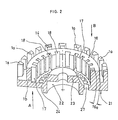
- the electromagnetic coil support 11 has radially outside (FIG. 2) individual magnetic yoke legs 1a, which in their cross-section 14 are aligned radially approximately to a needle engagement point 15 (FIG. 1). As a result, the space is optimally used for the electromagnetic coil 2.
- the opposite, radially inner magnetic yoke legs 1b are combined to form a closed ring 16.
- This ring 16 forms the prerequisite for further measures to store and guide the hinged anchor 3.
- there are radially inwardly directed teeth 17 on the closed ring 16 in such a way that the ring width 16a is enlarged in the radial direction by a tooth 17, whereby an increase in the area guiding the magnetic flux threads is achieved.
- a tooth gap 18 is created by a tooth 17, into which guide means 19 (FIG. 1) for the hinged anchors 3 can engage without interfering laterally.
- the needle engagement point 15 can consist of a folding anchor 3, against which a pressure needle head 4a loosely rests.
- the hinged anchor 3 can, however, also be firmly attached to the pressure needle 4 at the needle engagement point 15, e.g. by welding.
- the guide means 19 consist of rail-like projections 20, which are each arranged laterally in lateral recesses 3a in the hinged anchors 3. These lateral recesses 3a of the hinged anchor 3 allow the sliding movement of the Folding anchor 3 on the fixed projections 20.
- the fixed, rail-like projections 20 are injection molded according to FIG. 1 directly onto the front printhead housing 7 made of plastic. The described slidability comes about within tolerated limits in that the projections 20 run in the tooth gaps 18, the armature width 3b minus the recesses 3a on both sides and the tooth width 17a being tolerably the same size.
- the electromagnetic coil support 11 is designed according to FIGS. 2 to 5 as a one-piece sintered or investment casting component 21, which results in a high manufacturing accuracy in terms of shape, location and dimensions for the magnet yoke leg 1a, the centering of the closed ring 16, for the teeth 17 and for the Tooth gaps 18 and the tooth width 17a results.
- This accuracy is also ensured within the rear printhead housing 6 in that the one-piece component 21 made of sintered or investment casting is further developed into a central hub part 22.
- the hub part 22 consists of a hub base 23 and a disk 24 which connects the hub part 22 to the radially inner ring 16.
- a damping disk 25 bears against the hub base 23 (FIG. 1). This damping of the movements of the hinged armature 3 is improved by a considerably greater thickness 26 of the hub base 23 compared to the hub disk 24 (FIG. 4).
- the one-piece component 21 can also be made lighter by radially inner recesses 27 distributed over the circumference in the hub disk 24.
Landscapes
- Impact Printers (AREA)
Abstract
Description
- Die Erfindung betrifft einen Matrixnadeldruckkopf der Klappankerbauart mit mehreren Systemen, die jeweils aus einem Magnet jochschenkelpaar, einer Elektromagnetspule, einem Klappanker und einer Drucknadel bestehen, wobei eine höhere Systemzahl mit einem äußeren Druckkopfdurchmesser als Nenndurchmesser zugrundegelegt ist oder wobei eine niedrigere Systemzahl mit einem kleineren Druckkopfdurchmesser als dem Nenndurchmesser verbunden ist, ferner mit einem Elektromagnetspulenträger, der aus Sinter- oder Feinguß hergestellt ist und zusammen mit einer Grundplatte und den Magnetjochschenkelpaaren ein einstückiges Bauteil bildet.
- Ein derartiger Matrixnadeldruckkopf ist z.B. aus der DE-A1-34 12 855 oder aus der US-A1-4,230,038 bekannt. Die bekannten Lösungen weisen U-förmige Magnetjochschenkelpaare auf. Die Jochschenkel sind hierbei im Querschnitt rechteckförmig. Eine solche Gestaltung ist jedoch raum- und flächenbeanspruchend. Bei der Herstellung tritt das Problem von Lage-und von Formfehlern auf und bei Sinterteilen bzw. Feingußteilen treten Füllungsmängel in dem Herstellungswerkzeug auf. Derartige Füllungsmängel führen zu Ungleichmäßigkeiten des magnetischen Flusses. Der magnetische Fluß hängt u.a. von der Dichte des Werkstoffes ab. Außerdem entstehen Kalibrierungsprobleme des Werkstückes. Sämtliche Schwierigkeiten werden bei Steigerung der Anzahl der Systeme noch weiter erhöht. So ist es bei 18 oder 24 Systemen und mehr Systemen (gleichbleibender Nenndurchmesser vorausgesetzt) nur noch schwierig möglich, die Anker seitlich den Magnetjochschenkeln zuzuordnen bzw. die Anker zu führen.
- Der Erfindung liegt die Aufgabe zugrunde, insbesondere für hochzahlige Systeme (z.B. 18 oder 24) ohne Einbuße magnetischer Energie eine verbesserte, genaue Ankerführung vorzuschlagen und die geschilderten Nachteile zu beseitigen.
- Die gestellte Aufgabe wird erfindungsgemäß dadurch gelöst, daß der Elektromagnetspulenträger radial außen einzelne Magnetjochschenkel aufweist, die jeweils auf eine Nadelangriffsstelle zwischen Nadelkopf und Klappanker ausgerichtet sind, daß die radial inneren Magnetjochschenkel zu einem geschlossenen Ring geformt sind und daß an diesen geschlossenen Ring radial nach innen gerichtete Zähne angeformt sind, in deren Zahnlücken jeweils Führungsmittel für die Klappanker greifen. Vorteilhafterweise kann ein derartiger Elektromagnetspulenträger aus Sinter oder Feinguß mit hoher Toleranzgenauigkeit hergestellt werden, wobei weder Füllungsmängel im Herstellungswerkzeug auftreten noch Kalibrierungsprobleme des Werkstückes. Vor allen Dingen wird jedoch das Raum- und Flächenproblem gelöst, indem die Anker seitlich vorteilhaft geführt werden können. Die Erfindung eignet sich somit neben kleinen besonders für extrem hohe Systemzahlen.
- In weiterer Ausbildung der Erfindung bestehen die Führungsmittel für die Klappanker aus jedem Klappanker paarweise zugeordneten schienenähnlichen Vorsprüngen, die jeweils in seitlichen Ausnehmungen des Klappankers und weiter in den seitlichen Zahnlücken verlaufen, wobei die Ankerbreite abzüglich der Ausnehmungen und die Zahnbreite toleriert gleichgroß sind. Diese Lösung besitzt den Vorteil, daß die Querschnitte des Klappankers und der Magnetjochschenkelpaare an den Magnetfluß angepaßt sind, soweit dies erforderlich ist.
- Eine weitere Verbesserung der Erfindung besteht darin, daß das einstückige Bauteil aus Sinter- oder Feinguß zu einem zentrischen Nabenteil weitergebildet ist. Diese Lösung erleichtert die Festlegung sämtlicher Klappanker bzw. sämtlicher Systeme. Eine andere vorteilhafte Weiterentwicklung der Erfindung besteht darin, daß das Nabenteil aus einem Nabenboden und aus einer diesen mit dem geschlossenen radial inneren Ring verbindenden Scheibe besteht. Eine solche Gliederung, d.h. der Aufbau des Elektromagnetspulenträgers in einzeln stehende radial äußere Jochschenkel, radial innere Jochschenkel, die einen geschlossenen Ring bilden sowie in nach innen gerichtete Zähne, ferner in das Nabenteil und nunmehr auch noch in einen Nabenboden und diesen mit dem geschlossenen radial inneren Ring verbindenden Scheibe begünstigt die Herstellung des Elektromagnetspulenträgers beträchtlich und legt sämtliche funktionswichtigen Bauteile zueinander fest. Ein solcher Elektromagnetspulenträger kann daher mit geringsten Toleranzen hergestellt werden.
- In weiterer Verbesserung der Erfindung ist vorgesehen, daß der Nabenboden gegenüber der Nabenscheibe eine erheblich größere Dicke besitzt. Diese Maßnahme führt zu einer besonderen Massenverteilung im Bereich der Auflage eines noch zu beschreibenden Dämpfungsringes, so daß die Rückprallerscheinungen der Klappanker mit den Drucknadeln in einen äußerst günstigen Schwingungsbereich verlegt werden können.
- Eine Führung des Magnetflusses sowie eine Werkstoffersparnis wird noch dadurch erzielt, daß in der Nabenscheibe über den Umfang verteilte, radial innere Ausnehmungen vorgesehen sind.
- Weitere Maßnahmen zur Beeinflussung des Magnetflusses bzw. zur günstigen Herstellung des Elektromagnetspulenträgers werden dadurch erzielt, indem an dem einstückigen Bauteil von den Magnetjochschenkelpaaren axial abgewandt, zwischen jeweils zwei am Umfang benachbarten Magnetjochschenkeln, Einkerbungen für die Magnetflußlenkung vorgesehen sind.
- Ein Ausführungsbeispiel der Erfindung ist in der Zeichnung dargestellt und wird im folgenden näher beschrieben. Es zeigen
- Fig. 1 einen axialen Längsschnitt durch den Matrixnadeldruckkopf,
- Fig. 2 einen perspektivischen Querschnitt durch den Elektromagnetspulenträger,
- Fig. 3 eine Teilansicht von unten gegen den Elektromagnetspulenträger in Richtung A gemäß Fig. 2,
- Fig. 4 einen Querschnitt gemäß der Schnittangabe C - D aus Fig. 5 und
- Fig. 5 eine Draufsicht auf Fig. 4 bzw. in Richtung B gemäß Fig. 2.
- Der Matrixnadeldruckkopf der Klappankerbauart (Fig. 1) weist z.B. 9, 18, oder 24 Systeme auf, die jeweils aus einem Magnetjochschenkelpaar 1, einer auf einem der Magnetjochschenkel 1a aufgesteckten Elektromagnetspule 2, einem Klappanker 3 und einer Drucknadel 4 bestehen. Die Anzahl (9, 18, 24) dieser Systeme legt den Nenndurchmesser 5 fest. Die Systemzahl beträgt, wie gezeichnet, 24.
- Der Matrixnadeldruckkopf ist ferner in ein hinteres Druckkopfgehäuse 6 und ein vorderes Druckkopfgehäuse 7 gegliedert. Im vorderen Druckkopfgehäuse 7 sind die Drucknadeln 4 mittels Lagerscheiben 8 geführt bzw. gelagert. Alle 24 Drucknadeln 4 werden zu zwei Nadelspalten in einem Mundstück 9 zusammengeführt. Der komplette Matrixnadeldruckkopf ist außerdem durch zwei Führungszapfen 10 auf einem weiter nicht gezeigten Druckkopfschlitten justiert und befestigt.
- Im hinteren Druckkopfgehäuse 6 befinden sich nahezu alle System-Bauteile und außerdem ein Elektromagnetspulenträger 11, der in den Figuren 2 bis 5 näher dargestellt ist. Der Magnetspulenträger 11 verbindet durch eine Schraube 12 über eine Gehäusenabe 13 das hintere Druckkopfgehäuse 6 mit dem vorderen Druckkopfgehäuse 7.
- Der Elektromagnetspulenträger 11 besitzt radial außen (Fig. 2) einzelne Magnetjochschenkel 1a, die in ihrem Querschnitt 14 radial etwa auf eine Nadelangriffsstelle 15 (Fig. 1) ausgerichtet sind. Dadurch wird der Zwischenraum optimal für die Elektromagnetspule 2 ausgenutzt. Die gegenüberliegenden, radial inneren Magnetjochschenkel 1b sind im Gegensatz zu den einzelnen Magnetjochschenkeln 1a zu einem geschlossenen Ring 16 zusammengefaßt. Dieser Ring 16 bildet die Voraussetzung für weitere Maßnahmen, die Klappanker 3 zu lagern und zu führen. Zu diesem Zweck befinden sich an dem geschlossenen Ring 16 radial nach innen gerichtete Zähne 17, und zwar derart, daß die Ringbreite 16a durch einen Zahn 17 in radialer Richtung vergrößert wird, wodurch eine Vergrößerung der die Magnetflußfäden führenden Fläche erzielt wird. Gleichzeitig wird jedoch durch einen Zahn 17 eine Zahnlücke 18 geschaffen, in die Führungsmittel 19 (Fig. 1) für die Klappanker 3 greifen können, ohne sich seitlich zu stören.
- Die Nadelangriffsstelle 15 kann aus einem Klappanker 3 bestehen, an dem ein Drucknadelkopf 4a lose anliegt. Der Klappanker 3 kann jedoch auch fest mit der Drucknadel 4 an der Nadelangriffsstelle 15, z.B. durch Schweißen, verbunden sein.
- Im vorliegenden Ausführungsbeispiel bestehen die Führungsmittel 19 aus schienenähnlichen Vorsprüngen 20, die jeweils seitlich in seitlichen Ausnehmungen 3a der Klappanker 3 angeordnet sind. Diese seitlichen Ausnehmungen 3a der Klappanker 3 lassen eine gleitende Bewegung des Klappankers 3 an den feststehenden Vorsprüngen 20 zu. Die feststehenden, schienenähnlichen Vorsprünge 20 sind gemäß Fig. 1 unmittelbar an das vordere, aus Kunststoff hergestellte Druckkopfgehäuse 7 angespritzt. Die beschriebene Gleitfähigkeit kommt dadurch in tolerierten Grenzen zustande, daß die Vorsprünge 20 in den Zahnlücken 18 verlaufen, wobei die Ankerbreite 3b abzüglich der beiderseitigen Ausnehmungen 3a und die Zahnbreite 17a toleriert gleich groß sind.
- Der Elektromagnetspulenträger 11 ist gemäß den Fig. 2 bis 5 als einstückiges Sinter- oder Feingußbauteil 21 ausgeführt, wodurch sich eine hohe Herstellgenauigkeit bezüglich Form, Lage und Abmessungen für die Magnetjochschenkel 1a, die Zentrierung des geschlossenen Ringes 16, für die Zähne 17 und für die Zahnlücken 18 sowie die Zahnbreite 17a ergibt. Diese Genauigkeit wird auch innerhalb des hinteren Druckkopfgehäuses 6 noch dadurch gewährleistet, daß das einstückige Bauteil 21 aus Sinter- oder Feinguß zu einem zentrischen Nabenteil 22 weitergebildet ist. Das Nabenteil 22 besteht aus einem Nabenboden 23 und aus einer Scheibe 24, die das Nabenteil 22 mit dem radial inneren Ring 16 verbindet. An dem Nabenboden 23 liegt (Fig. 1) eine Dämpfungsscheibe 25 an. Diese Dämpfung der Bewegungen der Klappanker 3 wird durch eine erheblich größere Dicke 26 des Nabenbodens 23 gegenüber der Nabenscheibe 24 verbessert (Fig. 4).
- Das einstückige Bauteil 21 kann ferner leichter gestaltet werden durch in der Nabenscheibe 24 über den Umfang verteilte, radial innere Ausnehmungen 27.
- Weitere Werkstoff-Einsparungen, jedoch mit einer Funktionsbeeinflussung, werden durch zwischen jeweils zwei am Umfang des einstückigen Bauteils 21 benachbarte Magnetjochschenkel 1a durch Einkerbungen 28 erzielt, durch die außerdem eine Magnetflußlenkung erfolgt.
Claims (7)
daß der Elektromagnetspulenträger (11) radial außen einzelne Magnetjochschenkel (1a) aufweist, die jeweils auf eine Nadelangriffsstelle (15) zwischen Nadelkopf (4a) und Klappanker (3) ausgerichtet sind,
daß die radial inneren Magnetjochschenkel (1b) zu einem geschlossenen Ring (16) geformt sind und daß an diesen geschlossenen Ring (16) radial nach innen gerichtete Zähne (17) angeformt sind, in deren Zahnlücken (18) jeweils Führungsmittel (19) für die Klappanker (3) greifen.
daß die Führungsmittel (19) für die Klappanker (3) aus jedem Klappanker (3) paarweise zugeordneten schienenähnlichen Vorsprüngen (20) bestehen, die jeweils in seitlichen Ausnehmungen (3a) des Klappankers (3) und weiter in den seitlichen Zahnlücken (18) verlaufen, wobei die Ankerbreite (3b) abzüglich der Ausnehmungen (3a) und die Zahnbreite (17a) toleriert gleich groß sind.
daß das einstückige Bauteil (21) aus Sinter- oder Feinguß zu einem zentrischen Nabenteil (22) weitergebildet ist.
daß das Nabenteil (22) aus einem Nabenboden (23) und aus einer diesen mit dem geschlossenen, radial inneren Ring (16) verbindenden Scheibe (24) besteht.
daß der Nabenboden (23) gegenüber der Nabenscheibe (24) eine erheblich größere Dicke (26) besitzt.
daß in der Nabenscheibe (24) über den Umfang verteilte, radial innere Ausnehmungen (27) vorgesehen sind.
daß an dem einstückigen Bauteil (21) von den Magnetjochschenkelpaaren (1) axial abgewandt, zwischen jeweils zwei am Umfang benachbarten Magnetjochschenkeln (1a), Einkerbungen (28) für die Magnetflußlenkung vorgesehen sind.
Priority Applications (5)
| Application Number | Priority Date | Filing Date | Title |
|---|---|---|---|
| EP88730265A EP0371182B1 (de) | 1988-12-01 | 1988-12-01 | Matrixnadeldruckkopf der Klappankerbauart |
| AT88730265T ATE86552T1 (de) | 1988-12-01 | 1988-12-01 | Matrixnadeldruckkopf der klappankerbauart. |
| DE8888730265T DE3879212D1 (de) | 1988-12-01 | 1988-12-01 | Matrixnadeldruckkopf der klappankerbauart. |
| JP1310460A JPH02188265A (ja) | 1988-12-01 | 1989-11-29 | フラップ式アマチュア構成のドットマトリクス印字ヘッド |
| US07/443,755 US4979836A (en) | 1988-12-01 | 1989-11-30 | Matrix pin print head of the hinged-clapper-armature construction |
Applications Claiming Priority (1)
| Application Number | Priority Date | Filing Date | Title |
|---|---|---|---|
| EP88730265A EP0371182B1 (de) | 1988-12-01 | 1988-12-01 | Matrixnadeldruckkopf der Klappankerbauart |
Publications (2)
| Publication Number | Publication Date |
|---|---|
| EP0371182A1 true EP0371182A1 (de) | 1990-06-06 |
| EP0371182B1 EP0371182B1 (de) | 1993-03-10 |
Family
ID=8200563
Family Applications (1)
| Application Number | Title | Priority Date | Filing Date |
|---|---|---|---|
| EP88730265A Expired - Lifetime EP0371182B1 (de) | 1988-12-01 | 1988-12-01 | Matrixnadeldruckkopf der Klappankerbauart |
Country Status (5)
| Country | Link |
|---|---|
| US (1) | US4979836A (de) |
| EP (1) | EP0371182B1 (de) |
| JP (1) | JPH02188265A (de) |
| AT (1) | ATE86552T1 (de) |
| DE (1) | DE3879212D1 (de) |
Families Citing this family (3)
| Publication number | Priority date | Publication date | Assignee | Title |
|---|---|---|---|---|
| US5215389A (en) * | 1990-02-28 | 1993-06-01 | Citizen Watch Co., Ltd. | Print head for a dot matrix printer |
| DE102004028904B4 (de) * | 2004-06-15 | 2006-08-17 | Tallygenicom Computerdrucker Gmbh | Nadeldruckkopf für Matrixdrucker mit einem Druckkopfschlitten |
| DE102005021199B4 (de) * | 2005-05-07 | 2013-06-06 | Dascom Europe Gmbh | Matrixnadeldruckkopf für Computerdrucker |
Citations (5)
| Publication number | Priority date | Publication date | Assignee | Title |
|---|---|---|---|---|
| US4273452A (en) * | 1978-09-29 | 1981-06-16 | Tokyo Shibaura Denki Kabushiki Kaisha | Print head for a dot printer |
| US4407591A (en) * | 1980-08-21 | 1983-10-04 | Ing. C. Olivetti & C., S.P.A. | Ballistic wire matrix print head |
| EP0110662A2 (de) * | 1982-12-01 | 1984-06-13 | Tokyo Electric Co. Ltd. | Punktdruckkopf |
| EP0141522A1 (de) * | 1983-09-26 | 1985-05-15 | Tokyo Electric Co. Ltd. | Punktdruckkopf |
| EP0155816A2 (de) * | 1984-03-15 | 1985-09-25 | Tokyo Electric Co., Ltd. | Punktdruckkopf |
Family Cites Families (4)
| Publication number | Priority date | Publication date | Assignee | Title |
|---|---|---|---|---|
| US3860895A (en) * | 1974-05-28 | 1975-01-14 | Honeywell Inf Systems | Magnetic shunt assembly for bias field apparatus |
| DE3243475C2 (de) * | 1982-11-22 | 1987-02-26 | Mannesmann AG, 4000 Düsseldorf | Nadeldruckkopf für Matrixdrucker |
| JPS6323041U (de) * | 1986-07-28 | 1988-02-16 | ||
| JPS6384942A (ja) * | 1986-09-30 | 1988-04-15 | Toshiba Corp | プリンタヘツド用ヨ−クコア |
-
1988
- 1988-12-01 DE DE8888730265T patent/DE3879212D1/de not_active Expired - Fee Related
- 1988-12-01 EP EP88730265A patent/EP0371182B1/de not_active Expired - Lifetime
- 1988-12-01 AT AT88730265T patent/ATE86552T1/de not_active IP Right Cessation
-
1989
- 1989-11-29 JP JP1310460A patent/JPH02188265A/ja active Pending
- 1989-11-30 US US07/443,755 patent/US4979836A/en not_active Expired - Fee Related
Patent Citations (5)
| Publication number | Priority date | Publication date | Assignee | Title |
|---|---|---|---|---|
| US4273452A (en) * | 1978-09-29 | 1981-06-16 | Tokyo Shibaura Denki Kabushiki Kaisha | Print head for a dot printer |
| US4407591A (en) * | 1980-08-21 | 1983-10-04 | Ing. C. Olivetti & C., S.P.A. | Ballistic wire matrix print head |
| EP0110662A2 (de) * | 1982-12-01 | 1984-06-13 | Tokyo Electric Co. Ltd. | Punktdruckkopf |
| EP0141522A1 (de) * | 1983-09-26 | 1985-05-15 | Tokyo Electric Co. Ltd. | Punktdruckkopf |
| EP0155816A2 (de) * | 1984-03-15 | 1985-09-25 | Tokyo Electric Co., Ltd. | Punktdruckkopf |
Also Published As
| Publication number | Publication date |
|---|---|
| JPH02188265A (ja) | 1990-07-24 |
| DE3879212D1 (de) | 1993-04-15 |
| EP0371182B1 (de) | 1993-03-10 |
| US4979836A (en) | 1990-12-25 |
| ATE86552T1 (de) | 1993-03-15 |
Similar Documents
| Publication | Publication Date | Title |
|---|---|---|
| DE69320917T2 (de) | Anordnung zur Befestigung einer biegsamer Kopfaufhängung mit einem Trägerarm in einer Platteneinheit | |
| DE2636985C3 (de) | Tauchankermagnet, sowie dessen Verwendung in einem Drahtmatrixdrucker | |
| EP0357860B1 (de) | Matrixnadeldruckkopf der Klappankerbauart | |
| DE68913933T2 (de) | Punktnadelanschlagdrucker. | |
| EP0371182B1 (de) | Matrixnadeldruckkopf der Klappankerbauart | |
| DE2710015C3 (de) | Dreischenkligerer Magnetkopf mit zwei gegenüberliegend angeordneten U-förmigen Kernen | |
| DE3243475C2 (de) | Nadeldruckkopf für Matrixdrucker | |
| DE1424430B2 (de) | Magnetplattenspeicher | |
| DE69017382T2 (de) | Wandler mit variabler Induktanz. | |
| EP0188671B1 (de) | Verfahren zum Herstellen einer Ankerbaugruppe für einen Matrixdruckkopf | |
| DE69709635T2 (de) | Linearmesskopf mit axialer bewegung | |
| DE2407136A1 (de) | Wegeventil mit raste zur festlegung der schaltstellungen des steuerkolbens | |
| EP0371183B1 (de) | Matrixnadeldruckkopf der Klappankerbauart | |
| DE2323402A1 (de) | Elektromagnetischer uebertragerkopf | |
| DD149586A5 (de) | Vorrichtung zum magnetischen einschreiben und auslesen von signalen grosser bandbreite | |
| DE3878164T2 (de) | Drahtpunktdruckkopf. | |
| DE2445280C3 (de) | Verfahren zum Herstellen eines Mehrspur-Magnetkopfes | |
| DE69125355T2 (de) | Verfahren zur herstellung von druckkopfbauteile für nadelpunktanschlagdrucker | |
| EP0112274B1 (de) | Nadeldruckkopf für Matrixdrucker | |
| DE2735152C2 (de) | Loser Abstandskörper eines Kugelumlaufes einer Schraubverbindung | |
| DE2133925A1 (de) | Drehwinkel-Nachweiseinrichtung | |
| DE1514704C (de) | Spulenkörper | |
| EP1673534A1 (de) | Aufnahmeh lse f r einen aktork rper | |
| EP0188672B1 (de) | Matrixdruckkopf | |
| DE3115752A1 (de) | Lagerbefestigung und verfahren zum herstellen derselben |
Legal Events
| Date | Code | Title | Description |
|---|---|---|---|
| PUAI | Public reference made under article 153(3) epc to a published international application that has entered the european phase |
Free format text: ORIGINAL CODE: 0009012 |
|
| AK | Designated contracting states |
Kind code of ref document: A1 Designated state(s): AT BE CH DE FR GB IT LI NL |
|
| 17P | Request for examination filed |
Effective date: 19900523 |
|
| 17Q | First examination report despatched |
Effective date: 19911203 |
|
| GRAA | (expected) grant |
Free format text: ORIGINAL CODE: 0009210 |
|
| AK | Designated contracting states |
Kind code of ref document: B1 Designated state(s): AT BE CH DE FR GB IT LI NL |
|
| PG25 | Lapsed in a contracting state [announced via postgrant information from national office to epo] |
Ref country code: NL Effective date: 19930310 Ref country code: BE Effective date: 19930310 |
|
| REF | Corresponds to: |
Ref document number: 86552 Country of ref document: AT Date of ref document: 19930315 Kind code of ref document: T |
|
| ITF | It: translation for a ep patent filed | ||
| ET | Fr: translation filed | ||
| REF | Corresponds to: |
Ref document number: 3879212 Country of ref document: DE Date of ref document: 19930415 |
|
| GBT | Gb: translation of ep patent filed (gb section 77(6)(a)/1977) |
Effective date: 19930324 |
|
| NLV1 | Nl: lapsed or annulled due to failure to fulfill the requirements of art. 29p and 29m of the patents act | ||
| PG25 | Lapsed in a contracting state [announced via postgrant information from national office to epo] |
Ref country code: AT Effective date: 19931201 |
|
| PG25 | Lapsed in a contracting state [announced via postgrant information from national office to epo] |
Ref country code: LI Effective date: 19931231 Ref country code: CH Effective date: 19931231 |
|
| PLBE | No opposition filed within time limit |
Free format text: ORIGINAL CODE: 0009261 |
|
| STAA | Information on the status of an ep patent application or granted ep patent |
Free format text: STATUS: NO OPPOSITION FILED WITHIN TIME LIMIT |
|
| 26N | No opposition filed | ||
| REG | Reference to a national code |
Ref country code: CH Ref legal event code: PL |
|
| PGFP | Annual fee paid to national office [announced via postgrant information from national office to epo] |
Ref country code: GB Payment date: 19941114 Year of fee payment: 7 |
|
| PGFP | Annual fee paid to national office [announced via postgrant information from national office to epo] |
Ref country code: FR Payment date: 19941115 Year of fee payment: 7 |
|
| PG25 | Lapsed in a contracting state [announced via postgrant information from national office to epo] |
Ref country code: GB Effective date: 19951201 |
|
| GBPC | Gb: european patent ceased through non-payment of renewal fee |
Effective date: 19951201 |
|
| PG25 | Lapsed in a contracting state [announced via postgrant information from national office to epo] |
Ref country code: FR Effective date: 19960830 |
|
| REG | Reference to a national code |
Ref country code: FR Ref legal event code: ST |
|
| PGFP | Annual fee paid to national office [announced via postgrant information from national office to epo] |
Ref country code: DE Payment date: 20030219 Year of fee payment: 15 |
|
| PG25 | Lapsed in a contracting state [announced via postgrant information from national office to epo] |
Ref country code: DE Free format text: LAPSE BECAUSE OF NON-PAYMENT OF DUE FEES Effective date: 20040701 |
|
| PG25 | Lapsed in a contracting state [announced via postgrant information from national office to epo] |
Ref country code: IT Free format text: LAPSE BECAUSE OF NON-PAYMENT OF DUE FEES Effective date: 20051201 |