EP0110662A2 - Punktdruckkopf - Google Patents
Punktdruckkopf Download PDFInfo
- Publication number
- EP0110662A2 EP0110662A2 EP83307134A EP83307134A EP0110662A2 EP 0110662 A2 EP0110662 A2 EP 0110662A2 EP 83307134 A EP83307134 A EP 83307134A EP 83307134 A EP83307134 A EP 83307134A EP 0110662 A2 EP0110662 A2 EP 0110662A2
- Authority
- EP
- European Patent Office
- Prior art keywords
- armature
- yoke
- core
- armatures
- fulcrum
- Prior art date
- Legal status (The legal status is an assumption and is not a legal conclusion. Google has not performed a legal analysis and makes no representation as to the accuracy of the status listed.)
- Granted
Links
Images


Classifications
-
- B—PERFORMING OPERATIONS; TRANSPORTING
- B41—PRINTING; LINING MACHINES; TYPEWRITERS; STAMPS
- B41J—TYPEWRITERS; SELECTIVE PRINTING MECHANISMS, i.e. MECHANISMS PRINTING OTHERWISE THAN FROM A FORME; CORRECTION OF TYPOGRAPHICAL ERRORS
- B41J2/00—Typewriters or selective printing mechanisms characterised by the printing or marking process for which they are designed
- B41J2/22—Typewriters or selective printing mechanisms characterised by the printing or marking process for which they are designed characterised by selective application of impact or pressure on a printing material or impression-transfer material
- B41J2/23—Typewriters or selective printing mechanisms characterised by the printing or marking process for which they are designed characterised by selective application of impact or pressure on a printing material or impression-transfer material using print wires
- B41J2/27—Actuators for print wires
- B41J2/275—Actuators for print wires of clapper type
Definitions
- the present invention relates to a dot printer and, more particularly, to a dot printer head equipped with a radial array of armatures so actuatable as to selectively drive a multiplicity of needles.
- a second object of the invention resides in reducing the equivalent mass of each armature to perform a high-speed printing operation.
- a third object of the invention is to decrease the amount of power consumption.
- an armature is actuated by exciting a coil and thereby causes a needle to collide with a platen to perform a desired printing operation.
- a mechanism employed for driving the armature has a structure illustrated in Figs. 1 and 2.
- Coils (3) are wound individually around a plurality of cores (2) formed integrally with a yoke (1), and each of armatures (5) actuatable through excitation of the associated coil (3) for causing a needle (4) to collide with a platen is supported at a fulcrum (6) in such a manner as to be swingable upward and downward.
- And recesses (8) to be held by a guide member (7) are formed on the two sides of each armature (5).
- the guide member (7) is located within the surface opposed to the yoke (1).
- each recess (8) formed on the surface opposed to the yoke (1) must be located in the armature (5) due to the positional relation to the guide member (7), it becomes a requisite to increase the radial width t3 of the yoke (1) for attaining a greater surface area of the armature (5) opposed to the yoke (1).
- an increase of l3 brings about an increase of l1 to eventually widen an air gap G, whereby a sufficient force of magnetic attraction is rendered unattainable in the core (2).
- lever ratio l2/l1 is lowered with an increase of the distance l1 to consequently augment the equivelent mass of the armature (5), so that high-speed printing is rendered impossible with another disadvantage of consuming a larger amount of electric power.
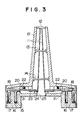
- FIG. 3 a first exemplary embodiment of the present invention will be described with reference to Figs. 3 through 9, in which needle guide members (12, 13, 14) for slidably holding a plurality of needles (11) are secured to a guide frame (10), and an annular yoke (15) is attached to the guide frame (10) with screws.
- a plurality of cores (17) equipped with coils (16) are disposed in a radial array integrally with the yoke (15).
- Each of armatures (18) located opposite to the core (17) and the yoke (15) has recesses (19) on the two sides thereof, and guide portions (20) formed integrally with the guide frame (10) are fitted into the recesses (19) so that each armature (18) is swingable upward and downward on a fulcrum (21) while being energized elastically by means of a spring (22) in the direction to return to the former position.
- the guide frame (10) further has guide portions (23) for preventing lateral deflection of the fore ends of the armature (18).
- the annular yoke (15) includes a disk-shaped region (25) along its inner circumference to hold an armature stopper (25) thereon.
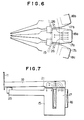
- Each armature (18) has, on its two sides, surfaces (26) defined between the core (17) and the fulcrum (21) and opposed in parallel to the adjacent armatures (18) in a length £5 with a small space t4 maintained.
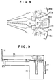
- the same effect is achievable by alternately reversing the directions of the respective magnetic fluxes induced from the coils (16), as illustrated in Fig. 8.
- the magnetic flux generated from the core (17a) partially flows to the yoke (15) via the armature (18a) and then returns to the core (17a) while the remaining flux component having reached the armature (18a) further flows therefrom to the adjacent armature (18b) or (18c) and arrives at the adjacent core (17b) or (17c).
- the ratio l2/l1 can be increased to bring about a reduction in the equivalent mass of the armature (18), so that the structure is rendered optimal for high-speed printing with an economic advantage regarding the power consumption.
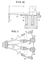
- each armature (27) is located outside of the associated core (17).
- Each armature (27) has surfaces (26) opposed to the adjacent armatures (27), and guide portions (29, 30) for guiding the two sides of the armature (27) are formed in the guide frame (10).
Landscapes
- Impact Printers (AREA)
Applications Claiming Priority (2)
| Application Number | Priority Date | Filing Date | Title |
|---|---|---|---|
| JP211969/82 | 1982-12-01 | ||
| JP57211969A JPS59101373A (ja) | 1982-12-01 | 1982-12-01 | ドツトプリンタヘツド |
Publications (3)
| Publication Number | Publication Date |
|---|---|
| EP0110662A2 true EP0110662A2 (de) | 1984-06-13 |
| EP0110662A3 EP0110662A3 (en) | 1985-08-28 |
| EP0110662B1 EP0110662B1 (de) | 1987-05-20 |
Family
ID=16614703
Family Applications (1)
| Application Number | Title | Priority Date | Filing Date |
|---|---|---|---|
| EP83307134A Expired EP0110662B1 (de) | 1982-12-01 | 1983-11-22 | Punktdruckkopf |
Country Status (4)
| Country | Link |
|---|---|
| US (1) | US4583871A (de) |
| EP (1) | EP0110662B1 (de) |
| JP (1) | JPS59101373A (de) |
| DE (1) | DE3371616D1 (de) |
Cited By (4)
| Publication number | Priority date | Publication date | Assignee | Title |
|---|---|---|---|---|
| EP0371183A1 (de) * | 1988-12-01 | 1990-06-06 | MANNESMANN Aktiengesellschaft | Matrixnadeldruckkopf der Klappankerbauart |
| EP0371182A1 (de) * | 1988-12-01 | 1990-06-06 | MANNESMANN Aktiengesellschaft | Matrixnadeldruckkopf der Klappankerbauart |
| EP0394060A3 (de) * | 1989-04-20 | 1991-01-02 | Tokyo Electric Co. Ltd. | Punkte-Druckknopf |
| US5039239A (en) * | 1988-08-01 | 1991-08-13 | Mannesmann Aktiengesellschaft | Matrix pin-print head of the hinged-clapper-armature construction |
Families Citing this family (7)
| Publication number | Priority date | Publication date | Assignee | Title |
|---|---|---|---|---|
| IT208062Z2 (it) * | 1986-07-25 | 1988-03-31 | Microlys Spa | Testina di stampa a matrice di punti |
| JPS6323041U (de) * | 1986-07-28 | 1988-02-16 | ||
| JPS6358909A (ja) * | 1986-08-29 | 1988-03-14 | エヌ・シー・アール・コーポレーション | 磁性体の磁気バイアス方法 |
| JPH0435176Y2 (de) * | 1986-11-25 | 1992-08-20 | ||
| IT1212158B (it) * | 1987-12-29 | 1989-11-08 | Olivetti & Co Spa | Dispositivo stampante a fili od aghi e relativo procedimento di montaggio |
| EP0343994A3 (de) * | 1988-05-27 | 1990-07-25 | Tokyo Electric Co., Ltd. | Punktdruckkopf |
| IT1232145B (it) * | 1989-07-14 | 1992-01-23 | Microlys Spa | Testina di stampa ad aghi per una stampante a matrice di punti ad alta definizione |
Family Cites Families (8)
| Publication number | Priority date | Publication date | Assignee | Title |
|---|---|---|---|---|
| US1318722A (en) * | 1919-10-14 | Combined transformer and maintaining reactance device for vapor | ||
| JPS5835475B2 (ja) * | 1977-06-13 | 1983-08-02 | エプソン株式会社 | ワイヤ式ドツトプリンタヘツドの構造 |
| US4230038A (en) * | 1977-06-23 | 1980-10-28 | Helmut Falk | Matrix print head assembly |
| US4230412A (en) * | 1978-03-17 | 1980-10-28 | Helmut Falk | Matrix print head assembly |
| JPS5849394B2 (ja) * | 1979-10-13 | 1983-11-04 | 谷村株式会社新興製作所 | ドットプリンタの印字駆動装置 |
| JPS56111683A (en) * | 1980-02-09 | 1981-09-03 | Nec Corp | Printing head |
| JPS5783464A (en) * | 1980-11-14 | 1982-05-25 | Brother Ind Ltd | Printing head of wire dot printer |
| JPS5826546U (ja) * | 1981-08-14 | 1983-02-19 | 東芝テック株式会社 | ドットプリンタヘッドのニ−ドル |
-
1982
- 1982-12-01 JP JP57211969A patent/JPS59101373A/ja active Granted
-
1983
- 1983-11-22 EP EP83307134A patent/EP0110662B1/de not_active Expired
- 1983-11-22 DE DE8383307134T patent/DE3371616D1/de not_active Expired
-
1985
- 1985-04-24 US US06/725,505 patent/US4583871A/en not_active Expired - Lifetime
Cited By (6)
| Publication number | Priority date | Publication date | Assignee | Title |
|---|---|---|---|---|
| US5039239A (en) * | 1988-08-01 | 1991-08-13 | Mannesmann Aktiengesellschaft | Matrix pin-print head of the hinged-clapper-armature construction |
| EP0371183A1 (de) * | 1988-12-01 | 1990-06-06 | MANNESMANN Aktiengesellschaft | Matrixnadeldruckkopf der Klappankerbauart |
| EP0371182A1 (de) * | 1988-12-01 | 1990-06-06 | MANNESMANN Aktiengesellschaft | Matrixnadeldruckkopf der Klappankerbauart |
| US5009529A (en) * | 1988-12-01 | 1991-04-23 | Mannesmann Aktiengesellschaft | Matrix print head of hinged-clapper-armature construction |
| EP0394060A3 (de) * | 1989-04-20 | 1991-01-02 | Tokyo Electric Co. Ltd. | Punkte-Druckknopf |
| US5056942A (en) * | 1989-04-20 | 1991-10-15 | Tokyo Electric Co., Ltd. | Dot printer head |
Also Published As
| Publication number | Publication date |
|---|---|
| JPH0332465B2 (de) | 1991-05-13 |
| DE3371616D1 (en) | 1987-06-25 |
| EP0110662B1 (de) | 1987-05-20 |
| US4583871A (en) | 1986-04-22 |
| EP0110662A3 (en) | 1985-08-28 |
| JPS59101373A (ja) | 1984-06-11 |
Similar Documents
| Publication | Publication Date | Title |
|---|---|---|
| US4583871A (en) | Dot printer head with magnetic circuit through adjacent armatures | |
| US4940958A (en) | Polarized electromagnetic apparatus | |
| JPH0235669B2 (de) | ||
| US4626115A (en) | Dot printer head | |
| US4820065A (en) | Wire-type printing head | |
| US4572681A (en) | Wire dot print head | |
| US4521122A (en) | Needle printer assembly | |
| JPH0673965B2 (ja) | プリンタ用アクチユエータ及びその製造方法 | |
| EP0117145B1 (de) | Punktschlagdruckkopf | |
| WO1990009285A1 (fr) | Tete d'impression par points | |
| US4798488A (en) | Dot matrix print head | |
| EP0269959B1 (de) | Druckkopf der Drahtbauart | |
| JPS5836469A (ja) | ドット印字ヘッド | |
| JPH0221395B2 (de) | ||
| EP0359133B1 (de) | Anschlagpunktdrucker | |
| JPH0719796Y2 (ja) | ワイヤドット印字ヘッド | |
| JPS6320712B2 (de) | ||
| EP0581463B1 (de) | Punktnadeldruckkopf | |
| JPH0716438Y2 (ja) | ワイヤドット印字ヘッド | |
| JPS60228169A (ja) | ドツトプリンタの電磁石装置 | |
| US5269610A (en) | Armature design in a wire matrix printing head | |
| JPS6232859Y2 (de) | ||
| JP2836100B2 (ja) | 印字ヘッド | |
| JPH01249459A (ja) | ドットプリンタの印字ヘッド | |
| JPS6154948A (ja) | ドツトプリンタヘツド |
Legal Events
| Date | Code | Title | Description |
|---|---|---|---|
| PUAI | Public reference made under article 153(3) epc to a published international application that has entered the european phase |
Free format text: ORIGINAL CODE: 0009012 |
|
| AK | Designated contracting states |
Designated state(s): DE FR GB |
|
| PUAL | Search report despatched |
Free format text: ORIGINAL CODE: 0009013 |
|
| AK | Designated contracting states |
Designated state(s): DE FR GB |
|
| 17P | Request for examination filed |
Effective date: 19850726 |
|
| 17Q | First examination report despatched |
Effective date: 19860807 |
|
| GRAA | (expected) grant |
Free format text: ORIGINAL CODE: 0009210 |
|
| AK | Designated contracting states |
Kind code of ref document: B1 Designated state(s): DE FR GB |
|
| REF | Corresponds to: |
Ref document number: 3371616 Country of ref document: DE Date of ref document: 19870625 |
|
| ET | Fr: translation filed | ||
| PLBE | No opposition filed within time limit |
Free format text: ORIGINAL CODE: 0009261 |
|
| STAA | Information on the status of an ep patent application or granted ep patent |
Free format text: STATUS: NO OPPOSITION FILED WITHIN TIME LIMIT |
|
| 26N | No opposition filed | ||
| PGFP | Annual fee paid to national office [announced via postgrant information from national office to epo] |
Ref country code: FR Payment date: 20011113 Year of fee payment: 19 |
|
| PGFP | Annual fee paid to national office [announced via postgrant information from national office to epo] |
Ref country code: GB Payment date: 20011121 Year of fee payment: 19 |
|
| PGFP | Annual fee paid to national office [announced via postgrant information from national office to epo] |
Ref country code: DE Payment date: 20011210 Year of fee payment: 19 |
|
| REG | Reference to a national code |
Ref country code: GB Ref legal event code: IF02 |
|
| PG25 | Lapsed in a contracting state [announced via postgrant information from national office to epo] |
Ref country code: GB Free format text: LAPSE BECAUSE OF NON-PAYMENT OF DUE FEES Effective date: 20021122 |
|
| PG25 | Lapsed in a contracting state [announced via postgrant information from national office to epo] |
Ref country code: DE Free format text: LAPSE BECAUSE OF NON-PAYMENT OF DUE FEES Effective date: 20030603 |
|
| GBPC | Gb: european patent ceased through non-payment of renewal fee | ||
| PG25 | Lapsed in a contracting state [announced via postgrant information from national office to epo] |
Ref country code: FR Free format text: LAPSE BECAUSE OF NON-PAYMENT OF DUE FEES Effective date: 20030731 |
|
| REG | Reference to a national code |
Ref country code: FR Ref legal event code: ST |