EP0371190A2 - Cassette pour le rangement d'articles allongés - Google Patents
Cassette pour le rangement d'articles allongés Download PDFInfo
- Publication number
- EP0371190A2 EP0371190A2 EP89108568A EP89108568A EP0371190A2 EP 0371190 A2 EP0371190 A2 EP 0371190A2 EP 89108568 A EP89108568 A EP 89108568A EP 89108568 A EP89108568 A EP 89108568A EP 0371190 A2 EP0371190 A2 EP 0371190A2
- Authority
- EP
- European Patent Office
- Prior art keywords
- cover part
- receptacles
- cassette according
- cassette
- strips
- Prior art date
- Legal status (The legal status is an assumption and is not a legal conclusion. Google has not performed a legal analysis and makes no representation as to the accuracy of the status listed.)
- Withdrawn
Links
Images

Classifications
-
- B—PERFORMING OPERATIONS; TRANSPORTING
- B65—CONVEYING; PACKING; STORING; HANDLING THIN OR FILAMENTARY MATERIAL
- B65D—CONTAINERS FOR STORAGE OR TRANSPORT OF ARTICLES OR MATERIALS, e.g. BAGS, BARRELS, BOTTLES, BOXES, CANS, CARTONS, CRATES, DRUMS, JARS, TANKS, HOPPERS, FORWARDING CONTAINERS; ACCESSORIES, CLOSURES, OR FITTINGS THEREFOR; PACKAGING ELEMENTS; PACKAGES
- B65D83/00—Containers or packages with special means for dispensing contents
- B65D83/02—Containers or packages with special means for dispensing contents for dispensing rod-shaped articles, e.g. needles
-
- B—PERFORMING OPERATIONS; TRANSPORTING
- B25—HAND TOOLS; PORTABLE POWER-DRIVEN TOOLS; MANIPULATORS
- B25H—WORKSHOP EQUIPMENT, e.g. FOR MARKING-OUT WORK; STORAGE MEANS FOR WORKSHOPS
- B25H3/00—Storage means or arrangements for workshops facilitating access to, or handling of, work tools or instruments
- B25H3/003—Holders for drill bits or the like
Definitions
- the invention relates to a cassette for storing elongated objects, in particular tools with a preferably small diameter, with a base part which is provided with receptacles for the objects, and with a cover part which closes the base part.
- the invention has for its object to design a cassette of the type mentioned in such a way that a simple, esp. Simultaneously filling all recordings is possible, however, when the cassette is used as intended, there is only access to one record and at the same time it is ensured that the objects accommodated in the recordings cannot migrate from one to the adjacent recording.
- the receptacles are in the form of grooves which form separating webs and which are open both towards the cover part and at least at one of their axial ends, and that the cover part is displaceable perpendicularly to the longitudinal direction of the grooves , is at a short distance from the free edges of the separators and overlaps the axially open ends of the grooves with an edge strip, the edge strip having a removal opening for the objects, which, depending on the position of the cover part, is brought into an aligned position with each of the receptacles can be, and that the cover part with at least one, extending in its direction of adjustment and pointing towards the recordings Side arranged bar is provided, which protrudes into the recesses in the end of the dividers.
- the progress achieved by the invention essentially consists in that the receptacles open towards the cover part can be equipped with the tools to be accommodated therein in a single work step, whereupon the receptacles are closed by placing the cover ice on the base part.
- the now protruding into the front recesses on the cover part ensure that no tools can get into the adjacent tool holder through the gap that is always present and necessary between the free end of the separating web and the cover part. This is always ensured by the length of the strips, regardless of the position of the cover part, which is correspondingly adjustable for removing the tools.
- the cover part has four strips arranged at a mutual spacing, of which the two outside strips each run directly on the edge of the cover part. This ensures that even shorter tools, which do not extend over the entire length of the tool holder, do not find a gap length sufficient for their passage.
- the strips expediently extend over the entire length of the cover part, the length of the cover part being at least twice the displacement path of the cover part determined by the overall width of the receptacles.
- the cover part advantageously has a substantially U-shaped shape in the cross section perpendicular to the direction of displacement, the two edge strips forming the legs of the U-profile and the side walls of the base part adjacent to them being in mutual engagement via dovetail-shaped sliding surfaces. This makes it possible to simply snap the cover part onto the base part from above after filling the base part with the tools.
- one or both edge strips of the cover part carry a projection which faces the side walls and which engages in locking recesses in the side wall which are arranged in the direction of displacement of the cover part in such a way that the projection opening extends into one of the locking recesses is centered on one of the images.
- a stop piece can also be provided on the cover part, which runs in a groove-like recess closed at the end, the length of which is equal to the displacement path of the cover part. This results in a front and rear stop seen in the direction of displacement when the cover part is adjusted to remove a tool.
- a detachably connected locking element is arranged on the base part, which protrudes against the front edge of the cover part in the opening direction. Since the cassettes are often hung on sales shelves, it is further recommended in the context of the invention that the locking member on one Suspension bracket is arranged, which is connected in the bottom plane of the base part facing away from the cover part via two connecting webs each provided with predetermined breaking points formed by notches.
- a locking member can be provided on each of the connecting webs and the locking member can be formed by a wedge-shaped projection, the surface of which facing the cover part is designed as a vertically projecting stop and the surface facing away from the cover part is designed as a wedge surface.
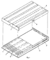
- the cassette shown in the drawing is used to store elongated objects, in particular Tools with a preferably small diameter, such as twist drills 1, as indicated in FIG. 1.
- the cassette consists in particular of a base part 2, which is provided with receptacles 3 for the objects 1, the receptacles 3 having the shape of grooves 4 forming between them. Furthermore, the cassette has a cover part 5, with which the base part 2 can be closed at least in the area of the receptacles 3.
- the grooves are open both towards the cover part 5 and at one of their axial ends.
- the axial opening is provided for the removal of the tool from the cassette or the insertion into the cassette, while the radial opening pointing towards the cover part 5 allows a very simple and simultaneous filling of all receptacles of the cassette with all the tools in a single step.
- the cover part 5 is displaceable perpendicular to the longitudinal direction of the grooves and is at a short distance from the free edges 4.1 of the dividers 4.
- the axially open ends of the grooves are overlapped by an edge strip 5.1 of the cover part 5, the edge strip having a removal opening 6 for the objects 1 which, depending on the position of the cover part 5, can be brought into an aligned position with each of the receptacles 3.
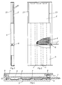
- the cover part 5 is provided with four, in its direction of adjustment strips 7, which are arranged on the side facing the receptacles 3 and protrude into frontal recesses 8 of the dividers 4. It is already sufficient if the end face of the strips 7 and the end face of the separating webs 4 lie in a common plane.
- the arrangement of the strips 7 is selected so that the two outside strips each run directly on the edge of the cover part 5.
- the strips 7 extend over the entire length of the cover part 5, which in turn is at least twice as long as the total width of the receptacles 3 and the displacement path of the cover part 5 determined thereby 4 essentially U-shaped shape, with the two edge strips 5.
- 1 forming the legs of the U-profile and the side walls 2.
- 1 of the base part 2 adjacent to them being in mutual engagement via dovetail-shaped sliding surfaces 9.
- At least one of the two edge strips 5.1 of the cover part 5 carries a projection, not shown in the drawing, which faces into the side walls 2.1 of the base part 2 and which engages in recesses 10 in the side wall 2.1.
- These locking recesses 10 are arranged in the direction of displacement of the cover part 5 such that when the projection protrudes into one of the locking recesses 10, the removal opening 6 is aligned centrally with one of the receptacles 3.
- a stop piece also not shown in detail, is provided on the cover part 5, which runs in a groove-like recess 11 closed at the end, the length of which is equal to the displacement path of the cover part 5.
- the base part 2 is first provided in a suspension bracket 13 which is connected in the base plane of the base part 2 facing away from the cover part 5 via two connecting webs 15.
- These connecting webs have predetermined breaking points 14, which in a particularly simple embodiment are simple Notches can be formed.
- This suspension bracket 13 is provided in the area of the connecting webs 15 each with a locking member 12 which projects against the front edge of the cover part 5 in the opening direction, as indicated in FIG. 6.
- the locking member 12 is formed by a wedge-shaped projection, the one surface facing the cover part 5 is designed as a vertically protruding stop, while the surface facing away from the cover part 5 has the shape of a wedge surface.
- the hanging tab 13 is bent away towards the bottom, as a result of which the hanging tab 13 detaches from the bottom part 2 at the predetermined breaking points 14.
- the anti-theft device is thus removed so that the cover part 5 can be opened in the manner already described.
Landscapes
- Engineering & Computer Science (AREA)
- Mechanical Engineering (AREA)
- Packaging Of Annular Or Rod-Shaped Articles, Wearing Apparel, Cassettes, Or The Like (AREA)
Priority Applications (1)
| Application Number | Priority Date | Filing Date | Title |
|---|---|---|---|
| JP30638789A JPH02180179A (ja) | 1988-11-26 | 1989-11-24 | 細長い物体を保存するための収納箱 |
Applications Claiming Priority (2)
| Application Number | Priority Date | Filing Date | Title |
|---|---|---|---|
| DE3839993A DE3839993A1 (de) | 1988-11-26 | 1988-11-26 | Kassette zur aufbewahrung von laenglichen gegenstaenden |
| DE3839993 | 1988-11-26 |
Publications (2)
| Publication Number | Publication Date |
|---|---|
| EP0371190A2 true EP0371190A2 (fr) | 1990-06-06 |
| EP0371190A3 EP0371190A3 (fr) | 1990-08-29 |
Family
ID=6367970
Family Applications (1)
| Application Number | Title | Priority Date | Filing Date |
|---|---|---|---|
| EP89108568A Withdrawn EP0371190A3 (fr) | 1988-11-26 | 1989-05-12 | Cassette pour le rangement d'articles allongés |
Country Status (3)
| Country | Link |
|---|---|
| US (1) | US4958732A (fr) |
| EP (1) | EP0371190A3 (fr) |
| DE (1) | DE3839993A1 (fr) |
Families Citing this family (24)
| Publication number | Priority date | Publication date | Assignee | Title |
|---|---|---|---|---|
| DE9313766U1 (de) * | 1993-09-11 | 1993-11-25 | Rösler, Peter, 88239 Wangen | Verpackungsbehälter |
| USD358537S (en) | 1994-05-19 | 1995-05-23 | Leseman James D | Machine tool holder |
| DE29519081U1 (de) * | 1995-12-01 | 1996-02-01 | Knoblauch, Georg, 89537 Giengen | Kassette für Stichsägeblätter |
| US5813532A (en) * | 1996-10-08 | 1998-09-29 | Credo Tool Company | Router bit case |
| USD403508S (en) * | 1996-10-08 | 1999-01-05 | Credo Tool Company | Router bit case |
| USD394806S (en) | 1997-05-12 | 1998-06-02 | Georg Knoblauch | Two-piece drill package |
| US6755302B1 (en) | 1998-08-14 | 2004-06-29 | Black & Decker Inc. | Tool container |
| US6405864B1 (en) | 1998-08-14 | 2002-06-18 | Black & Decker Inc. | Tool container |
| USD446018S1 (en) | 1998-08-14 | 2001-08-07 | Black & Decker Inc. | Tool receiving insert |
| USD451202S1 (en) | 1999-03-05 | 2001-11-27 | Pharmacia & Upjohn Ab | Transport tray for ampoule parts |
| USD437684S1 (en) | 1999-08-11 | 2001-02-20 | Black & Decker Inc. | Tool container |
| USD477912S1 (en) | 2002-10-02 | 2003-08-05 | Irwin Industrial Tool Company | Drill bit case |
| USD477714S1 (en) | 2002-10-02 | 2003-07-29 | Irwin Industrial Tool Company | Drill bit case |
| USD481868S1 (en) | 2002-10-02 | 2003-11-11 | Irwin Industrial Tool Company | Drill bit case |
| US7225923B2 (en) * | 2002-12-17 | 2007-06-05 | Irwin Industrial Tool Company | Multi-configured tool bit box |
| US7195120B2 (en) * | 2003-04-30 | 2007-03-27 | Irwin Industrial Tool Company | Tool bit storage and display container |
| USD505068S1 (en) | 2003-04-30 | 2005-05-17 | Irwin Industrial Tool Company | Flip-top loose tool bit container |
| USD516310S1 (en) | 2004-11-18 | 2006-03-07 | Black & Decker Inc. | Tool container |
| USD516808S1 (en) | 2004-11-18 | 2006-03-14 | Black & Decker Inc. | Tool container |
| US7325682B2 (en) * | 2005-04-12 | 2008-02-05 | Irwin Industrial Tool Company | Storage case having cover of two slidably-related portions |
| DE102011054998B4 (de) * | 2011-11-02 | 2013-06-27 | BAM Bundesanstalt für Materialforschung und -prüfung | Aufbewahrungs- und Transportbox für Glaskapillaren mit Probenmaterial |
| US9987741B2 (en) | 2015-02-12 | 2018-06-05 | Techtronic Industries Co. Ltd. | Tool bit case |
| US10449665B2 (en) * | 2017-04-12 | 2019-10-22 | Gregory R Ernst | Bit organizer |
| US11453113B1 (en) * | 2021-05-13 | 2022-09-27 | Chih-Chien Hsieh | Three axis limiting tool placement device |
Family Cites Families (10)
| Publication number | Priority date | Publication date | Assignee | Title |
|---|---|---|---|---|
| BE558845A (fr) * | ||||
| US1024388A (en) * | 1911-03-30 | 1912-04-23 | George H Bartlett | Tool-holding box. |
| GB457855A (en) * | 1935-06-04 | 1936-12-04 | Robert Barlow | Improvements in or relating to boxes or receptacles for powder or other materials |
| GB721527A (en) * | 1952-04-17 | 1955-01-05 | Heinrich Kruft | Improvements in and relating to boxes |
| US2792934A (en) * | 1954-05-03 | 1957-05-21 | Rocchetti Vittorio | Tool case with recessed bottom |
| US3176838A (en) * | 1962-12-27 | 1965-04-06 | Duval Corp | Electrical element packages |
| US3499525A (en) * | 1968-08-09 | 1970-03-10 | Hanson Whitney Co The | Universal criss-cross container for packaging multi-sized threaded taps |
| GB1310858A (en) * | 1972-03-03 | 1973-03-21 | Torrington Co | Package for elongated elements |
| US4162005A (en) * | 1977-12-12 | 1979-07-24 | Linger Harrison K | Artist brush box |
| US4598822A (en) * | 1985-02-19 | 1986-07-08 | Megatool Inc. | Drill bit carrying case |
-
1988
- 1988-11-26 DE DE3839993A patent/DE3839993A1/de not_active Withdrawn
-
1989
- 1989-05-12 EP EP89108568A patent/EP0371190A3/fr not_active Withdrawn
- 1989-11-16 US US07/437,827 patent/US4958732A/en not_active Expired - Fee Related
Also Published As
| Publication number | Publication date |
|---|---|
| DE3839993A1 (de) | 1990-05-31 |
| US4958732A (en) | 1990-09-25 |
| EP0371190A3 (fr) | 1990-08-29 |
Similar Documents
| Publication | Publication Date | Title |
|---|---|---|
| DE3839993A1 (de) | Kassette zur aufbewahrung von laenglichen gegenstaenden | |
| EP0476343B1 (fr) | Boîte pour jeux de tournevis | |
| DE2248408B1 (de) | Behaelter zur aufnahme einer kassette mit einem bandfoermigen aufzeichnungstraeger | |
| DE2213024B2 (de) | Spender fuer rasierklingeneinheiten | |
| DE2113434C3 (de) | Behälter zur Aufnahme und einzelnen Ausgabe von Schreibstiftminen | |
| DE2910099C2 (fr) | ||
| EP0440909B1 (fr) | Ratelier à outils | |
| DE1943766C3 (de) | Einrichtung zum Einschlagen von Wellennägeln | |
| DE2935206C2 (de) | Kassette | |
| CH683807A5 (de) | Vorrichtung zur Aufnahme von Schallplatten-, Tonband- oder Videokassetten. | |
| DE3204101A1 (de) | Aufbewahrungsbox fuer magnetbandkassetten | |
| DE3719170C1 (en) | Receiving and securing device for drills (bits) | |
| DE9306650U1 (de) | Kassette zur Aufbewahrung mehrerer plattenförmiger Datenträger o.dgl. | |
| DE9401206U1 (de) | Deckel für einen Behälter | |
| DE7901753U1 (de) | "vorrichtung zum befestigen des winkelfoermigen gehaeuses einer eckumlenkung in hinterschnittenen nuten eines fluegelrahmens" | |
| DE2041066B2 (de) | Kiste für Flaschen | |
| EP0379620A1 (fr) | Boîte de stockage pour articles allongés | |
| AT403345B (de) | Sicherheitsvorrichtung für behältnisse wie beispielsweise videokassetten, audiokassetten, cd-boxen od. dgl. | |
| EP1035031A2 (fr) | Support pour forêt | |
| DE69028927T2 (de) | Doppel-cd-halter | |
| DE2008963A1 (de) | Kassette für Werkzeuge | |
| EP0439709B1 (fr) | Emballage plat pour plusieurs articles allongés agencés parallèlement | |
| DE4015314A1 (de) | Vorrichtung zum stehenden aufbewahren von viereckigen, steifen huellen | |
| DE4019487A1 (de) | Kassette zur aufbewahrung von gegenstaenden | |
| EP0086787A1 (fr) | Plaque-support pour cassette a bande magnetique sonore destinee a etre conservee dans un boitier |
Legal Events
| Date | Code | Title | Description |
|---|---|---|---|
| PUAI | Public reference made under article 153(3) epc to a published international application that has entered the european phase |
Free format text: ORIGINAL CODE: 0009012 |
|
| AK | Designated contracting states |
Kind code of ref document: A2 Designated state(s): DE FR GB NL |
|
| PUAL | Search report despatched |
Free format text: ORIGINAL CODE: 0009013 |
|
| AK | Designated contracting states |
Kind code of ref document: A3 Designated state(s): DE FR GB NL |
|
| 17P | Request for examination filed |
Effective date: 19910108 |
|
| STAA | Information on the status of an ep patent application or granted ep patent |
Free format text: STATUS: THE APPLICATION HAS BEEN WITHDRAWN |
|
| 18W | Application withdrawn |
Withdrawal date: 19920204 |