EP0371456A2 - Appareil d'enregistrement/reproduction à bande magnétique - Google Patents
Appareil d'enregistrement/reproduction à bande magnétique Download PDFInfo
- Publication number
- EP0371456A2 EP0371456A2 EP89121933A EP89121933A EP0371456A2 EP 0371456 A2 EP0371456 A2 EP 0371456A2 EP 89121933 A EP89121933 A EP 89121933A EP 89121933 A EP89121933 A EP 89121933A EP 0371456 A2 EP0371456 A2 EP 0371456A2
- Authority
- EP
- European Patent Office
- Prior art keywords
- signals
- digital
- acoustic
- magnetic tape
- recording
- Prior art date
- Legal status (The legal status is an assumption and is not a legal conclusion. Google has not performed a legal analysis and makes no representation as to the accuracy of the status listed.)
- Granted
Links
- 230000015654 memory Effects 0.000 claims description 63
- 238000006243 chemical reaction Methods 0.000 claims description 34
- 238000005070 sampling Methods 0.000 claims description 25
- 230000000875 corresponding effect Effects 0.000 description 12
- 230000033458 reproduction Effects 0.000 description 7
- 230000003111 delayed effect Effects 0.000 description 6
- 238000010276 construction Methods 0.000 description 5
- 238000010586 diagram Methods 0.000 description 2
- 238000005352 clarification Methods 0.000 description 1
- 230000000694 effects Effects 0.000 description 1
- 230000006870 function Effects 0.000 description 1
Images

Classifications
-
- H—ELECTRICITY
- H04—ELECTRIC COMMUNICATION TECHNIQUE
- H04N—PICTORIAL COMMUNICATION, e.g. TELEVISION
- H04N5/00—Details of television systems
- H04N5/76—Television signal recording
- H04N5/91—Television signal processing therefor
- H04N5/92—Transformation of the television signal for recording, e.g. modulation, frequency changing; Inverse transformation for playback
- H04N5/926—Transformation of the television signal for recording, e.g. modulation, frequency changing; Inverse transformation for playback by pulse code modulation
- H04N5/9265—Transformation of the television signal for recording, e.g. modulation, frequency changing; Inverse transformation for playback by pulse code modulation with processing of the sound signal
- H04N5/9267—Transformation of the television signal for recording, e.g. modulation, frequency changing; Inverse transformation for playback by pulse code modulation with processing of the sound signal using time division multiplex of the PCM audio and PCM video signals
- H04N5/9268—Transformation of the television signal for recording, e.g. modulation, frequency changing; Inverse transformation for playback by pulse code modulation with processing of the sound signal using time division multiplex of the PCM audio and PCM video signals with insertion of the PCM audio signals in the vertical blanking interval of the PCM video signal
-
- G—PHYSICS
- G11—INFORMATION STORAGE
- G11B—INFORMATION STORAGE BASED ON RELATIVE MOVEMENT BETWEEN RECORD CARRIER AND TRANSDUCER
- G11B20/00—Signal processing not specific to the method of recording or reproducing; Circuits therefor
- G11B20/10—Digital recording or reproducing
- G11B20/10527—Audio or video recording; Data buffering arrangements
-
- H—ELECTRICITY
- H04—ELECTRIC COMMUNICATION TECHNIQUE
- H04N—PICTORIAL COMMUNICATION, e.g. TELEVISION
- H04N5/00—Details of television systems
- H04N5/76—Television signal recording
- H04N5/91—Television signal processing therefor
- H04N5/93—Regeneration of the television signal or of selected parts thereof
- H04N5/937—Regeneration of the television signal or of selected parts thereof by assembling picture element blocks in an intermediate store
Definitions
- the present invention relates to a magnetic tape recording/reproducing device generally called DAT (digital audio tape recorder) for recording /reproducing digital signals.
- DAT digital audio tape recorder
- a magnetic tape recording/reproducing device called DAT (digital audio tape recorder) is capable of recording and reproducing acoustic sounds by converting them to a digital form on a magnetic tape. Additional information for correcting recording errors, such as parity error can be recorded simultaneously, so that even when part of the information to be recorded is omitted, an original sound can be accurately reproduced with considerably less noise.
- operational modes are selected which correspond to the acoustic signals to be recorded on 2 channel, 4 chanel mode and so on.
- the channels are recording ranges assigned to the number of acoustic signals to be recorded.
- Two channel mode provides for two acoustic signals to be recorded and reproduced and therefore two acoustic signals can be reproduced by two speakers which correspond to the front-left and front-right sides of the audience.
- the four channel mode can record four kinds of acoustic signals for recording and reproduction, so that four kinds of acoustic signals can be reproduced by four speakers which correspond to the front-left and front-right and rear-left and rear-right sides of the audience.
- the invention is to provide a magnetic tape recording/reproducing device with much wider application and improved utility.
- a magnetic tape recording/reproducing device comprising: acoustic A/D converting means for converting an analog acoustic signal into a digital acoustic signal by sampling the analog signal during the first sampling cycle; video AD converting means for converting an analog video signal into a digital video signal by sampling the analog video signal during the second sampling cycle at each field or frame; recording means for recording on magnetic tape sequentially during the first sampling cylce the digital acoustic signal converted by the acoustic A/D converting means and the digital video signal converted by the video A/D converting means; and reproducing means for reproducing the digital acoustic signals and the digital video signals recorded on the magnetic tape.
- the reproducing means preferably comprises: reading means for reading sequentially during the first sampling cycle the digital acoustic signals and the digital video signals recorded on the magnetic tape; acoustic D/A converting means for converting the digital acoustic signal read by the reading means into an analog acoustic signal; first and second memory means in which the digital video signals can be written; writing means for writing the digital signals read by the reading means alternately into the first and second memory means at each field or frame; read-out means for reading out alternately from the first and second memory means the digital video signals written by the writing means after completing writing of the signals at each field or frame; and video D/A converting means for converting the digital video signals read out by the read-out means into analog video signals.
- the recording means preferably comprises: first and second memory means in which each has a memory range whereby digital signals at each field or frame can be written; writing means for writing the digital acoustic signals converted by the acoustic A/D converting means sequentially into the first memory means and for writing the digital video signals converted by the video A/D converting means into the second memory means in each cycle of one field or frame; read-out means for reading out of the first and second memory means after completion of writing at the entire memory range of the first and second memory means the digital acoustic signals and the digital video signals in the order of their writing sequence in the memories; and tape recording means for recording on the magnetic tape during the first sampling cycle sequentially the digital acoustic signals and digital video signals read out by the read-out means.
- the acoustic signals and the video signals can be sequentially recorded on magnetic tape, and when reproducing both the acoustic and video signals, the video signals can be displayed on a display device such as CRT (Cathode Ray Tube) and the acoustic signals can be converted to sound by the speakers, etc.
- a display device such as CRT (Cathode Ray Tube) and the acoustic signals can be converted to sound by the speakers, etc.
- the first sampling frequency for converting analog acoustic signals into digital acoustic signals uses such variations of frequencies as 32 kHz, 44.1 kHz or 48 kHz.
- Acoustic A/D converting means employs such a construction which samples analog acoustic signals with a frequency of 32 kHz to convert the signals into digital acoustic signals of 12 bits.
- video A/D converting means employs such a construction which samples analog video signals with a frequency of 14.3 kHz to convert the signals into digital video signals of 8 bits.
- the invention preferably employs a recording means that enables so-called 4 channel mode recording to record sequentially on a magnetic tape four kinds of digital acoustic signals at the beginning of each sampling cycle.
- Fig. 1 is a block diagram showing the essential construction of the magnetic tape recording/reproducing device 31 as one embodiment of the present invention.
- the magnetic tape recording/reproducing device 31 can make recording/reproducing operation in the so-called 4 channel mode that records and reproduces acoustic signals corresponding to four speakers arranged front-left and front-right and rear-left and rear-right sides of the audience.
- two of the channels are assigned to acoustic signals and the remaining channels to video signals.
- the acoustic signals are of two kinds corresponding to the speakers located at the front-right and front-left sides of the audience.
- A/D conversion circuit 32, 33 analog acoustic signals input are sampled, for example, with sampling frequency of 32 kHz and converted into digital signals d1, d2 for example of 12 bits.
- the digital acoustic signals d1, d2 are sequentially applied to Serial/Parallel conversion circuit 34 (called hereunder “S/P”) from the A/ D conversion circuit 32 , 33, and further fed in parallel at every 8 bits to data bus 35.
- S/P Serial/Parallel conversion circuit 34
- Video signals are input through input terminal VO and applied to the A/D conversion circuit 36 to be converted into digital signals d3.
- the A/D conversion circuit 36 samples input analog video signals with sampling frequency, for example, of 14. 3 NHz to convert the analog video signals into digital video signals d3 for example of 8 bits and feeds the same in parallel to the data bus 35.
- the digital video signals d3 are written in one image memory 36a among image memories 36a, 36b which are memory means and connected to the data bus 35.
- a still picture of one scene is expressed by a video signal on one field, i.e, at 1/60 sec.
- writing of the digital signals d3 for one scene into the image memory 36a requires a time of 1/60 sec.
- Digital acoustic signal d4 applied to the data bus 35 by the S/P conversion circuit 34 is writtten in the other image memory 36b which has not been used for memorizing the digital video signals d3.
- the digital acoustic signals d4 written in the image memory 36b are not read out before writing the digital acoustic signals into an entire memory range of the image memory 36b is completed. then memorizing of the entire memory range is completed, the digital acoustic signals are read out sequentially from previously memorized one by one and fed to the data bus 35.
- P/S Parallel/Serial
- the digital acoustic signals serially taken from P/S conversion circuit 37 are directed to input terminals 91, 92 of the changeover switch 39. Also, the digital video signals taken serially from the P/S conversion circuit 38 are applied to the input terminal 93 of the changeover switch 39. The digital video signals sequentially and circularly flow between the output terminal 94 and the input terminals 91 - 93 at the changeover switch 93, so that digital signals d5 directed to line 40 from the output terminal 94 are applied to a recording signal processing unit 41.
- input digital signals d5 are modulated and errors are corrected by parity.
- the processed signals are recorded on magnetic tape 42 through a rotary head (not shown).
- the signals are applied through the rotary head to the signal processing unit 43.
- the signals are modulated and signals errors are corrected by parity.
- the reproduced signals are applied through the line 44 to an input terminal 64 at the changeover switch 64.
- Output terminals 61, 62 of the changeover switch 46 are each connected to Digital/Analog (called hereunder "D/A") conversion circuit 47, 48 respectively. Also, an output terminal 63 is connected to S/P conversion circuit 49. Changeover operation (described later) of switch 46 allows the reproduced signals to flow sequentially and circularly between the input terminal 64 and the output terminals 61 - 63. In this way, the D/A conversion circuit 47, 48 is given digital acoustic signals d7, d8 corresponding to speakers arranged at front-right and front- left sides of the audience. In the D/A conversion cirucit 47, 48, the digital acoustic signals d7, d8 are converted into analog acoustic signals and directed to output terminals R1, L1 at the magnetic tape recording/reproducing device 31.
- the digital video signal d9 is fed to the S/P conversion circuit 49 in parallel at every 8 bits to the data bus 35.
- the digital video signal d10 in that way is input to one of the image memories 36a, or 36b, leaving the other to supply the content of its memory to the D/A conversion circuit 51 through the data bus 35 and line 50.
- the other image memory During writing of the digital video memory d10 into any one of the image memories, the other image memory allows its contents to be cyclically read out at every 1/60 sec, so that video signals expressing still pictures corresponding to digital video signals recorded in any one of the abovementioned memories are sequentially fed to an output terminal V1 connected to the D/A conversion circuit 51.
- the video signals expressing a still picture can be displayed on a CRT (Cathode Ray Tube)
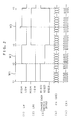
- Fig. 2 is a timing chart clarifying operation of the magnetic tape recording/reproducing device 31.
- Fig. 2 (1) and Fig. 2 (2) show switch-control signals LR, LR1 given to the changeover switches 39 (46) .
- Fig. 2 (3) shows a switching operation of the changeover switches 39 (46), and
- Fig. 2(4) shows digital signals d5 (d6) fed to the output terminals 94 (input terminal 64) of the changeover switches 39 (46).
- Fig. 2(5) shoes a clock signal CK1 generated in the record signal processing unit 41 (reproduced signal processing unit 43).
- Fig.2 (3) shows a change of use of input terminals 91 , 92, 93 (output terminals 61, 62, 63) connected to the output terminal 94 (input terminal 64) of the changeover switches 39 (46).
- the changeover switch 39 (46) can be connected to the input terminal 92 (output terminal 62) and further to input terminal 93 (output terminal 63) when the switch-control signal LR1 is at a high level.
- the switch-control signals LR, LR1 are both at low levels, so that the output terminal 94 is connected to the input terminal 91, whereby digital acoustic signals from the P/S convertion circuit are given to the record signal processing unit 41.
- the digital acoustic signals fed to unit 41 during the terminal correspond to those for a speaker arranged at the front-right side of the audience.
- the record signal processing unit 41 takes for each and every bit of the digital signals d5 through the output terminal 94 and the line 40 synchronously with the rise of the clock signal CK1.
- the switch control signal LR is at a high level while the switch control signal LR1 is at a low level, and during this period of time digital signals fed to the input terminal 92 from the P/S conversion circuit 37 are taken into the record signal processing unit 41.
- the digital acoustic signal is fed to a speaker arranged at the front-left side of the audience.
- the switch control signal LR1 is at a high level, so that the output terminal 94 at the changeover switch 39 is connected to the input terminal 93.
- the digital video signals from the P/S conversion circuit 38 are input for each and every bit to the record signal processing unit 41.
- the switch control signal LR rises so that the switch control signal LR reaches a high level during the period of time of t4 - t5. However, when the switch control signal is at high level, there is no corresponding effect on switch 39.
- the sampling frequency used at A/D conversion circuit 32, 33 is 32 kHz as mentioned.
- the switch control signal LR1 has a frequency of 32 kHz.
- analog acoustic signals input to the A/ D conversion cirucuit 32, 33 are converted into digital acoustic signals d1, d2 of 12 bits, so that digital acoustic signals taken into the record signal processing unit 41 during the term W1, W2 are digital signals of 12 bits.
- digital video signals taken into the record signal processing unit 41 during the period W3 are digital signals of 24 bits.
- the switch control signal LR1 has a frequency of 32 kHz and digital video signals of 24 bits are read into the record signal processing unit 41 during each cycle of the switch control signal LR1
- the amount of data R, of digital video signals stored in the image memory 36a and read out at 1 sec intervals is represented as follows.
- R 32 (kHz) x 24 (bits) - 768 (k bits/sec) (2)
- P/R 2.49 (sec) (3)
- video signals input from the input terminal VO are to be recorded in the magnetic tape 42 through the record signal processing unit 41 at a time interval as follows: 2.49 (sec) + 1/60 (sec) ⁇ 2.5 (sec) (4)
- Acoustic signals input through the input terminals RO, LO are temporarily stored in the image memory 36b.
- writing of digital acoustic signals into the image memory 36b at a data amount corresponding to the memory capacity P requires the time interval represented by the abovesaid formula (3) , i.e., 2.49 (sec) .
- the entire range of digital acoustic signals are written into the memory 36b, it supplies sequentially to the P/S conversion circuit 37 the signals written from the earliest to the latest.
- the digital acoustic signals fed to the input terminals 91, 92 at the changeover switch 39 from the P/S conversion circuit 37 are to be delayed for about 2.5 sec with respect to acoustic signals input through the input terminals RO, LO.
- the magnetic tape 42 is operated to record the digital video signals first, followed by the digital acoustic signals.
- digital acoustic signals corresponding to the digital video signals recorded in the magnetic tape 42 are to be delayed in recording for about 2.5 sec with respect to the digital video signals.
- Signals read out from the magnetic tape 42 through the rotary head, etc are fed to the reproduced signal processing unit 43 and sequentially to each and every bit, to the line 44 synchronously with the rise of the clock signal CK1. Accordingly, during the period W1, the digital signals d6 are applied as digital acoustic signals d7 to the D/A conversion circuit 47. During the period W2, the digital signals are applied as digital acoustic signals d8 to the D/A conversion circuit 48, and during W3 as digital video signals 49 to the S/P conversion circuit 49.
- each digital signal d6 fed to the line 44 during the periods W1 and W2 are the digital acoustic signals corresponding to the speakers arranged at the front-right and front-left sides of the audience, and those fed to the line 44 during the period W3 are digital video signals.
- Digital video signals d10 output from the S/P conversion circuit 49 are written sequentially, for example, into one image memory 36a.
- the time required for writing digital video signals at one field into the image memory 36a is about 2. 5 sec., similar to that required for reading-out the digital video signals from the image memory 36a to the record signal processing unit 41.
- the image memory 36a feeds out all of the digital video signals to the line 50 and then to the D/A conversion circuit 51 at 1/60 sec. The operation runs continuously.
- the image memories 36a, 36b have alternate operations to each other, so that when one image memory is being read out, the other image memory is being given new information in the form of digital video signals. This feature allows a new still picture to be displayed about every 2.5 sec or more on a device connected with the output terminal V1.
- Analog acoustic signals corresponding to digital signals d7, d8 of the digital signals d6 fed out to the line 44 from the reproduced signal processing unit 43 are output from terminals R1, L1 without being delayed.
- Analog video signals corresponding to digital video signals d9 are fed to the output terminal V1 with a delay of about 2.5 sec since they must be memorized in the image memories 36a, 36b.
- digital acoustic signals corresponding to digital video signals expressing a still picture have been recorded on magnetic tape 42 with a delay of about 2.
- the invention makes possible the recording of sounds and images by the use of digital signals and the reproduction of still pictures and sounds by use of digital signals in the so-call DAT (DegitalAudio Tape Recorder). thereby remarkably improving the utility of DAT.
- DAT DegitalAudio Tape Recorder
- units for recording and reproducing of video signals are referred to as every one field. This unit may alternatively be at every frame.
- the recording time of magnetic tape shown by the formula (4) is represented as follows. 4.98 (sec) + 1/30 (sec) ⁇ 5 (sec) (4)
- This feature causes the digital acoustic signals fed to the P/S conversion circuit 91, 92 to be delayed about 5 sec with respect to acoustic signals input through the input terminals RO, LO, so that the digital acoustic signals are recorded in the magnetic tape 42 with a delay of about 5 sec with respect to digital video signals.
- digital video signals are fed out at 1/30 sec intervals from the image memories 36a, 36b after writing has been completed, to the D/A conversion circuit 51 through the line 50, so that the display device connected to the output terminal V1 displays still pictures that change at a time interval of about 5 sec or more.
- a 2 channel mode only may be available other than the 4 channel mode referred to in the abovesaid embodiment.
- one of the channels is assigned to recording/reproducing operation of the video signals.
- one channel may be assigned to the recording/reproducing of video signals.
- the digital acoustic signals can be delayed during the recording operation, but may alternatively be delayed upon operation to reproduce the sound with the same effects.
- two memories are used to record digital video signals and the remaining one for recording and delay of acoustic signals during reproduction.
- the present invention provides a further extension of the use of a magnetic tape recording/reproducing device and particularly improves the function of the device.
Landscapes
- Engineering & Computer Science (AREA)
- Multimedia (AREA)
- Signal Processing (AREA)
- Signal Processing For Digital Recording And Reproducing (AREA)
- Television Signal Processing For Recording (AREA)
- Signal Processing Not Specific To The Method Of Recording And Reproducing (AREA)
Applications Claiming Priority (2)
| Application Number | Priority Date | Filing Date | Title |
|---|---|---|---|
| JP303432/88 | 1988-11-29 | ||
| JP63303432A JPH0675339B2 (ja) | 1988-11-29 | 1988-11-29 | 磁気テープ記録/再生装置 |
Publications (3)
| Publication Number | Publication Date |
|---|---|
| EP0371456A2 true EP0371456A2 (fr) | 1990-06-06 |
| EP0371456A3 EP0371456A3 (fr) | 1991-12-27 |
| EP0371456B1 EP0371456B1 (fr) | 1994-10-26 |
Family
ID=17920934
Family Applications (1)
| Application Number | Title | Priority Date | Filing Date |
|---|---|---|---|
| EP89121933A Expired - Lifetime EP0371456B1 (fr) | 1988-11-29 | 1989-11-28 | Appareil d'enregistrement/reproduction à bande magnétique |
Country Status (4)
| Country | Link |
|---|---|
| US (1) | US5138500A (fr) |
| EP (1) | EP0371456B1 (fr) |
| JP (1) | JPH0675339B2 (fr) |
| DE (1) | DE68919052T2 (fr) |
Cited By (1)
| Publication number | Priority date | Publication date | Assignee | Title |
|---|---|---|---|---|
| EP0488752A3 (en) * | 1990-11-30 | 1992-09-09 | Sony Corporation | Digital signal recording apparatus using a rotary head |
Families Citing this family (4)
| Publication number | Priority date | Publication date | Assignee | Title |
|---|---|---|---|---|
| JPH04323982A (ja) * | 1991-04-23 | 1992-11-13 | Sharp Corp | 記録再生装置 |
| JPH05336483A (ja) * | 1991-07-31 | 1993-12-17 | Matsushita Electric Ind Co Ltd | 高品位カラー映像信号および音声信号の磁気記録再生装置 |
| AU4282193A (en) * | 1992-04-10 | 1993-11-18 | Avid Technology, Inc. | Method for visually and audibly representing computer instructions for editing video |
| US5491498A (en) * | 1993-11-15 | 1996-02-13 | Koyama; Ryo | Digital audio delivery in a graphics controller architecture |
Family Cites Families (8)
| Publication number | Priority date | Publication date | Assignee | Title |
|---|---|---|---|---|
| DE2949813C2 (de) * | 1979-12-11 | 1987-04-30 | Bts-Systementwicklungs Gmbh, 1000 Berlin | Vorrichtung zur Aufzeichnung von in elektrischen Signalen vorliegenden Bild- und Toninformationen auf einer Bildplatte |
| NL187211C (nl) * | 1981-02-27 | Uniroyal Inc | Werkwijze voor de bereiding van een expandeerbaar mengsel, werkwijze voor de bereiding van geexpandeerde polymere materialen, alsmede werkwijze voor de bereiding van een hydrazodicarbonzuurester als bij verhitting gasafsplitsend middel. | |
| JPS58164383A (ja) * | 1982-03-25 | 1983-09-29 | Sony Corp | ビデオ信号記録装置 |
| US4602295A (en) * | 1982-10-23 | 1986-07-22 | Pioneer Electronic Corporation | Recording and reproducing method for video format signal |
| JPH0690774B2 (ja) * | 1983-03-30 | 1994-11-14 | ソニー株式会社 | ディジタルディスクの再生装置 |
| JPH0824363B2 (ja) * | 1985-06-18 | 1996-03-06 | カシオ計算機株式会社 | 磁気記録再生装置 |
| JPS63282901A (ja) * | 1987-05-14 | 1988-11-18 | Matsushita Electric Ind Co Ltd | ディジタル音声記録ビデオテ−プレコ−ダ |
| DE3789543T2 (de) * | 1987-01-27 | 1994-11-10 | Hitachi Ltd | Verfahren und Gerät zur PCM-Aufzeichnung und -Wiedergabe eines Audiosignals. |
-
1988
- 1988-11-29 JP JP63303432A patent/JPH0675339B2/ja not_active Expired - Fee Related
-
1989
- 1989-11-28 DE DE68919052T patent/DE68919052T2/de not_active Expired - Fee Related
- 1989-11-28 EP EP89121933A patent/EP0371456B1/fr not_active Expired - Lifetime
- 1989-11-29 US US07/442,599 patent/US5138500A/en not_active Expired - Fee Related
Cited By (2)
| Publication number | Priority date | Publication date | Assignee | Title |
|---|---|---|---|---|
| EP0488752A3 (en) * | 1990-11-30 | 1992-09-09 | Sony Corporation | Digital signal recording apparatus using a rotary head |
| US5313339A (en) * | 1990-11-30 | 1994-05-17 | Sony Corporation | Apparatus using a rotary head for recording digital video and audio signals at double speed |
Also Published As
| Publication number | Publication date |
|---|---|
| EP0371456B1 (fr) | 1994-10-26 |
| EP0371456A3 (fr) | 1991-12-27 |
| JPH02148466A (ja) | 1990-06-07 |
| DE68919052D1 (de) | 1994-12-01 |
| US5138500A (en) | 1992-08-11 |
| JPH0675339B2 (ja) | 1994-09-21 |
| DE68919052T2 (de) | 1995-06-14 |
Similar Documents
| Publication | Publication Date | Title |
|---|---|---|
| SU1003774A3 (ru) | Устройство дл воспроизведени аналогового цветного видеосигнала с магнитной ленты | |
| US4816928A (en) | Apparatus for recording reproducing a still image and corresponding audio information in respective tracks on a disk with the audio compressed on segments of a track | |
| GB2054244A (en) | Editing digital signals | |
| JPH0824363B2 (ja) | 磁気記録再生装置 | |
| EP0338812B1 (fr) | Appareil et procédé pour l'enregistrement/reproduction sur bande magnétique de signaux vidéo numériques et de signaux audio numériques correspondants | |
| EP0371456A2 (fr) | Appareil d'enregistrement/reproduction à bande magnétique | |
| US5138501A (en) | Magnetic recorder/reproducer for recording digital signal on a plurality of tracks of magnetic recording media and reproducing the same | |
| US5392165A (en) | Apparatus for recording audio and video signals | |
| JP2619455B2 (ja) | 映像信号の記録方法ならびに再生方法およびこれらを用いた装置 | |
| JP2653940B2 (ja) | 磁気テープ記録再生装置 | |
| US5521766A (en) | Method and apparatus for reproducing digital acoustic and video signals | |
| JP2695306B2 (ja) | 磁気テープ記録再生装置 | |
| EP0548359B1 (fr) | Dispositif de reproduction de signaux numeriques a vitesse variable | |
| JP2801428B2 (ja) | 記録再生装置 | |
| JP2807098B2 (ja) | 記録再生装置 | |
| JP3214136B2 (ja) | ディジタル信号記録装置 | |
| JPH02193367A (ja) | 磁気テープ記録再生装置 | |
| JP3086129B2 (ja) | 映像信号の記録再生方法および装置 | |
| JP3123050B2 (ja) | 記録装置 | |
| JPH0530355B2 (fr) | ||
| JPH0549041A (ja) | 磁気記録再生システム | |
| JPH0338180A (ja) | ダビングシステム | |
| JPH04324169A (ja) | 記録再生装置 | |
| JPH01272384A (ja) | ディジタル静止画像記録再生方式 | |
| JPH04325988A (ja) | 記録再生装置 |
Legal Events
| Date | Code | Title | Description |
|---|---|---|---|
| PUAI | Public reference made under article 153(3) epc to a published international application that has entered the european phase |
Free format text: ORIGINAL CODE: 0009012 |
|
| AK | Designated contracting states |
Kind code of ref document: A2 Designated state(s): DE GB |
|
| 17P | Request for examination filed |
Effective date: 19901227 |
|
| PUAL | Search report despatched |
Free format text: ORIGINAL CODE: 0009013 |
|
| AK | Designated contracting states |
Kind code of ref document: A3 Designated state(s): DE GB |
|
| 17Q | First examination report despatched |
Effective date: 19920729 |
|
| GRAA | (expected) grant |
Free format text: ORIGINAL CODE: 0009210 |
|
| AK | Designated contracting states |
Kind code of ref document: B1 Designated state(s): DE GB |
|
| REF | Corresponds to: |
Ref document number: 68919052 Country of ref document: DE Date of ref document: 19941201 |
|
| PLBE | No opposition filed within time limit |
Free format text: ORIGINAL CODE: 0009261 |
|
| STAA | Information on the status of an ep patent application or granted ep patent |
Free format text: STATUS: NO OPPOSITION FILED WITHIN TIME LIMIT |
|
| 26N | No opposition filed | ||
| PGFP | Annual fee paid to national office [announced via postgrant information from national office to epo] |
Ref country code: GB Payment date: 19971119 Year of fee payment: 9 |
|
| PGFP | Annual fee paid to national office [announced via postgrant information from national office to epo] |
Ref country code: DE Payment date: 19971127 Year of fee payment: 9 |
|
| PG25 | Lapsed in a contracting state [announced via postgrant information from national office to epo] |
Ref country code: GB Free format text: LAPSE BECAUSE OF NON-PAYMENT OF DUE FEES Effective date: 19981128 |
|
| GBPC | Gb: european patent ceased through non-payment of renewal fee |
Effective date: 19981128 |
|
| PG25 | Lapsed in a contracting state [announced via postgrant information from national office to epo] |
Ref country code: DE Free format text: LAPSE BECAUSE OF NON-PAYMENT OF DUE FEES Effective date: 19990901 |