EP0371494A2 - Modenkoppler für Monopulsanwendungen - Google Patents
Modenkoppler für Monopulsanwendungen Download PDFInfo
- Publication number
- EP0371494A2 EP0371494A2 EP89122043A EP89122043A EP0371494A2 EP 0371494 A2 EP0371494 A2 EP 0371494A2 EP 89122043 A EP89122043 A EP 89122043A EP 89122043 A EP89122043 A EP 89122043A EP 0371494 A2 EP0371494 A2 EP 0371494A2
- Authority
- EP
- European Patent Office
- Prior art keywords
- mode
- waveguide
- coupling
- mode coupler
- coupler according
- Prior art date
- Legal status (The legal status is an assumption and is not a legal conclusion. Google has not performed a legal analysis and makes no representation as to the accuracy of the status listed.)
- Withdrawn
Links
Images


Classifications
-
- H—ELECTRICITY
- H01—ELECTRIC ELEMENTS
- H01Q—ANTENNAS, i.e. RADIO AERIALS
- H01Q25/00—Antennas or antenna systems providing at least two radiating patterns
- H01Q25/04—Multimode antennas
-
- H—ELECTRICITY
- H01—ELECTRIC ELEMENTS
- H01P—WAVEGUIDES; RESONATORS, LINES, OR OTHER DEVICES OF THE WAVEGUIDE TYPE
- H01P1/00—Auxiliary devices
- H01P1/16—Auxiliary devices for mode selection, e.g. mode suppression or mode promotion; for mode conversion
Definitions
- the invention relates to a mode coupler for monopulse applications according to the preamble of claim 1 as e.g. is known from DE-36 04 432 A1. A similar arrangement is described in DE-36 04 431 A1.
- the mode coupler known from DE-36 04 432 A1 consists of a main waveguide: in which several modes can be propagated and are attached to the mode-selective coupling / decoupling gates.
- the coupling / decoupling gates are all simple standard waveguides attached to the main waveguide, in which only the H10 basic wave type is capable of spreading.
- the dimensions of the main waveguide are chosen so large in the known mode coupler that all relevant waveguide modes are capable of propagation. However, the dimensions are not so large that undesirable waveguide modes spread, which can lead to faulty received signals.
- a mode-sensitive coupling of the H10 and H20 waves gives a sum and a difference diagram (arrow diagram) in the elevation.
- the H10 mode is coupled out at the end of the waveguide train in a straight line after the main waveguide has been gradually reduced to the standard waveguide format.
- the H20 mode is decoupled by a side-mounted waveguide.
- the (H11 + E11) wave which provides the difference diagram in azimuth, is transferred in the known mode coupler in the main waveguide with a separating plate in two antiphase waveguide shafts, as known in principle from EP-PS 0061 576. Your energy is then selectively coupled into the side-mounted waveguide using a coupling bracket.
- the similarly constructed mode coupler for monopulse applications in an antenna feed system from DE-36 04 431 A1 also serves to obtain angular deposits in azimuth and elevation and consists of a main waveguide in which several modes can be propagated and are attached to the mode-selective coupling / decoupling gates.
- Another coupling / decoupling gate for coupling / decoupling a mode orthogonal to the sum mode is implemented as a simple waveguide attached to the main waveguide, in which only the H 1 -wave wave type is made is spreadable.
- a metallic reflector is inserted in the main waveguide, which reflects the orthogonal mode in the attached waveguide.
- the object of the invention is to provide a mode coupler of the type mentioned at the outset, which allows further modes to be decoupled.
- the invention is characterized in claim 1.
- the further claims contain advantageous developments and exemplary embodiments of the invention.
- the structure of the mode coupler (FIG. 1) is identical in its basic structure to the known arrangement cited at the beginning.
- the dimensions of a main waveguide HH are to be chosen so large that all relevant waveguide modes are capable of spreading. However, the dimensions must not be so large that undesirable waveguide modes spread, which can lead to faulty received signals.
- By mode-sensitive coupling of the H10 and H20 wave the field images of FIG. 2a, a sum and a difference diagram (arrow diagram) are obtained in the elevation (FIG. 2b).
- This part of the arrangement is identical to the arrangement described in Skolnik's textbook.
- the H10 mode is coupled out at the end of the waveguide train in a straight line after the main waveguide HH has been gradually reduced to the standard waveguide format, H4.
- the H20 mode is coupled out through a laterally attached waveguide H3.
- the (H11 + E11) wave which provides the difference diagram in azimuth, is transferred in the mode coupler according to the invention in the main waveguide HH with a separating plate B into two antiphase waveguide shafts, as is known in principle from EP-PS 0061 570. Your energy is then selectively coupled with a coupling bracket K in the side-mounted waveguide H2.
- Figures 2c and 2d show the field image and the radiation lobe of the (H11 + E11) wave.
- the mode coupler according to the invention contains coupling openings for decoupling one of the H1on mode orthogonal mode, which is referred to as H01 mode. Its field image and the radiation lobes can be seen in FIGS. 2c and 2d.
- H01 mode is reflected and coupled out into the symmetrical to the main waveguide HH outgoing waveguide H11 and H10 through slots.
- These two waveguides are brought together via an H-level junction HV, so that the performance of the H01 mode can be dissipated in the waveguide H1.
- the waveguide waves of the H10 mode and the H20 mode are not disturbed by the divider B.
- the H10 basic wave type is capable of spreading. They are preferably designed as standard waveguides.
- a metallized dielectric can also be used, on which the coupling structures are produced by etching.
- the simple construction of the mode coupler according to the invention allows production using the electroforming process. This type of production is particularly advantageous for applications at mm wavelengths.
- a pyramid horn or a grooved horn can be easily integrated at the antenna output of the mode coupler, so that the shape and width of the radiation lobes of the antenna feed system can be influenced.
- the version with a grooved horn in particular provides the advantage of identical radiation lobes for the two orthogonal sum modes.
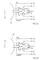
- FIG. 3 shows the possible operating modes of the antenna feed system when using a reflector antenna (main reflector HR, subreflector SR). If the transmit signal S is switched to the H10 gate with the aid of a PIN diode switch PS (the circulators Z serve to decouple the transmit and receive branch), the following signals reflected by the target can be received with the mode coupler MK according to the invention (FIG.
- H10 gate sum signal, portion not rotated in the direction of polarization ( ⁇ ⁇ ) H20 gate, (H11 + E11) gate: difference signals , portions not rotated in the direction of polarization ( ⁇ e ⁇ , ⁇ a ⁇ ) H01 gate: sum signal, portion rotated in the polarization direction by 90 ° ( ⁇ ).
- H10 gate sum signal, portion rotated by 90 ° in the direction of polarization ( ⁇ ).
- H01 gate sum signal, portion not rotated in the polarization direction ( ⁇ ⁇ ).
- both non-polarization-rotating and polarization-rotating targets can be detected and targeted with maximum sensitivity, or conclude from the ratio of the powers in both polarizations to the properties of the target.
- the reflections of undesired targets can be partially suppressed in this way.
- a polarization converter can be provided at the antenna output A of the mode coupler for transmitting and receiving circular polarization.
- This polarization converter must act on all wave types involved and must therefore be arranged as a flat arrangement in front of the mode coupler (e.g. disk made of birefringent material). The advantages of the arrangement described above are retained because, depending on the direction of rotation of the reflected, i.A. elliptically polarized signal can still be distinguished between targets that maintain the direction of rotation of the wave when reflected and those that reverse the direction of rotation.
Landscapes
- Variable-Direction Aerials And Aerial Arrays (AREA)
- Radar Systems Or Details Thereof (AREA)
Abstract
Description
- Die Erfindung betrifft einen Modenkoppler für Monopulsanwendungen nach dem Oberbegriff des Anspruchs 1, wie er z.B. aus der DE-36 04 432 A1 bekannt ist. Eine ähnliche Anordnung ist in der DE-36 04 431 A1 beschrieben.
- Der aus der DE-36 04 432 A1 bekannte Modenkoppler besteht aus einem Haupthohlleiter: in welchem mehrere Moden ausbreitungsfähig sind, und an den modenselektive Ein/Auskoppeltore angesetzt sind. Die Ein/Auskoppeltore sind sämtlich einfache, an den Haupthohlleiter angesetzte Norm-Hohlleiter, in denen nur der H₁₀-Grundwellentyp ausbreitungsfähig ist.
- Die Abmessungen des Haupthohlleiters sind bei dem bekannten Modenkoppler so groß gewählt, daß alle relevanten Hohlleitermoden ausbreitungsfähig sind. Die Abmessungen sind jedoch nicht so groß, daß sich unerwünschte Hohlleitermoden ausbreiten, die zu fehlerhaften Empfangssignalen führen können. Durch modensensitive Auskopplung der H₁₀- und der H₂₀-Welle erhält man ein Summen-und ein Differenzdiagramm (Peildiagramm) in der Elevation. Der H₁₀-Mode wird am Ende des Hohlleiterzuges in gerader Linie ausgekoppelt, nachdem der Haupthohlleiter stufenweise bis auf Normhohlleiterformat reduziert wurde. Der H₂₀-Mode wird durch einen seitlich angesetzten Hohlleiter ausgekoppelt. Die (H₁₁+E₁₁)-Welle, die das Differenzdiagramm im Azimut liefert, wird beim bekannten Modenkoppler im Haupthohlleiter mit einem Trennblech in zwei gegenphasige Hohlleiterwellen überführt, wie im Prinzip aus der EP-PS 0061 576 bekannt. Ihre Energie wird dann selektiv mit einem Koppelbügel in den seitlich aufgesetzten Hohlleiter eingekoppelt.
- Der ähnlich aufgebaute Modenkoppler für Monopulsanwendungen in einem Antennenspeisesystem aus der DE-36 04 431 A1 dient ebenfalls zum Gewinnen von Winkelablagen in Azimut und Elevation und besteht aus einem Haupthohlleiter, in welchem mehrere Moden ausbreitungsfähig sind, und an den modenselektive Ein/Auskoppeltore angesetzt sind. Ein weiteres Ein/Auskoppeltor zum Ein/Auskoppeln eines dem Summenmode orthogonalen Modes ist als einfacher, an den Haupthohlleiter angesetzter Hohlleiter realisiert, in dem nur der H₁₀-Grundwellentyp aus breitungsfähig ist. Ein metallischer Reflektor ist in den Haupthohlleiter eingesetzt, der den orthogonalen Mode in den angesetzten Hohlleiter reflektiert.
- Weitere Modenkoppler für Monopulsanwendungen sind z.B. im Lehrbuch von Skolnik, "Radar Handbook", Mc Graw Hill 1970, Kap. 21, S. 18 ff, in der EP-PS 0061 576 und der EP-PS 0041 077 beschrieben.
- Nachteil dieser letztgenannten bekannten Koppler ist jedoch, daß sie zum Gewinnen eines der beiden Ablagesignale eine kompliziert herzustellende Auskopplung einschließlich einer EH-Verzweigung (Magisches T) verwenden. Bei der im Lehrbuch von Skolnik beschriebenen Anordnung tritt z.B. an einem Ausgang der EH-Verzweigung das vom (H₁₁+E₁₁)-Mode gebildete Differenzsignal auf, während am zweiten Ausgang ein Anteil des Summensignals ausgekoppelt werden kann. Dieser Anteil muß durch besondere Maßnahmen mit dem am eigentlichen Summentor auszukoppelnden Summensignal zusammengeführt werden, was weiteren konstruktiven Aufwand benötigt.
- Aufgabe der Erfindung ist es, einen Modenkoppler der eingangs genannten Art anzugeben, der die Auskopplung weiterer Moden gestattet. Die Erfindung ist im Patentanspruch 1 gekennzeichnet. Die weiteren Ansprüche beinhalten vorteilhafte Weiterbildungen und Ausführungsbeispiele der Erfindung.
- Die Erfindung wird im folgenden anhand der Figuren näher erläutert.
- FIG. 1 zeigt ein Ausführungsbeispiel des er findungsgemäßen Modenkopplers.
- In den Figuren 2a-d sind die Feldbilder der ausgenutzten Hohlleitermoden und die zugehörigen Strahlungskeulen dargestellt.
- Die Figuren 3a-b zeigen die möglichen Betriebsarten in einem Antennenspeisesystem.
- Der Aufbau des Modenkopplers (FIG. 1) ist im Grundaufbau identisch mit der eingangs zitierten bekannten Anordnung. Die Abmessungen eines Haupthohlleiters HH sind so groß zu wählen, daß alle relevanten Hohlleitermoden ausbreitungsfähig sind. Die Abmessungen dürfen jedoch nicht so groß sein, daß sich unerwünschte Hohlleitermoden ausbreiten, die zu fehlerhaften Empfangssignalen führen können. Durch modensensitive Auskopplung der H₁₀-und H₂₀-Welle, deren Feldbilder der FIG. 2a zu entnehmen sind, erhält man ein Summen- und ein Differenzdiagramm (Peildiagramm) in der Elevation (FIG. 2b). Dieser Teil der Anordnung ist mit der im Lehrbuch von Skolnik beschriebenen Anordnung identisch. Der H₁₀-Mode wird am Ende des Hohlleiterzuges in gerader Linie ausgekoppelt, nachdem der Haupthohlleiter HH stufenweise bis auf Normhohlleiterformat, H₄, reduziert wurde. Der H₂₀-Mode wird durch einen seitlich angesetzten Hohlleiter H₃ ausgekoppelt. Die (H₁₁+E₁₁)-Welle, die das Differenzdiagramm im Azimut liefert, wird beim erfindungsgemäßen Modenkoppler im Haupthohlleiter HH mit einem Trennblech B in zwei gegenphasige Hohlleiterwellen überführt, wie im Prinzip aus der EP-PS 0061 570 bekannt. Ihre Energie wird dann selektiv mit einem Koppelbügel K in den seitlich aufgesetzten Hohlleiter H₂ eingekoppelt. Die Figuren 2c und 2d zeigen das Feldbild und die Strahlungskeule der (H₁₁+E₁₁)-Welle.
- Weiterhin enthält der erfindungsgemäße Modenkoppler Koppelöffnungen zum Auskoppeln eines des H₁₀-Mode orthogonalen Modes, der als H₀₁-Mode bezeichnet wird. Sein Feldbild und die Strahlungskeulen sind den Figuren 2c und 2d zu entnehmen. An der Vorderkante des Trennblechs B wird der H₀₁-Mode reflektiert und in die symmetrisch an den Haupt-Hohlleiter HH angeschlossenen Abgangshohlleiter H₁₁ und H₁₀ durch Schlitze ausgekoppelt. Diese beiden Hohlleiter werden über eine H-Ebenen-Verzweigung HV zusammengeführt, so daß im hohlleiter H₁ die Leistung des H₀₁-Modes abgeführt werden kann. Die Hohlleiterwellen des H₁₀-Modes und des H₂₀-Modes werden vom Trennblech B nicht gestört.
- In allen vom Haupthohlleiter abzweigenden Koppelhohlleitern ist nur der H₁₀-Grundwellentyp ausbreitungsfähig. Sie werden vorzugsweise als Normhohlleiter ausgeführt. Statt des Trennblechs B kann auch ein metallisiertes Dielektrikum verwendet werden, auf dem die Koppelstrukturen ätztechnisch hergestellt sind.
- Der einfache Aufbau des erfindungsgemäßen Modenkopplers erlaubt eine Herstellung nach den Elektroforming-Verfahren.Diese Art der Herstellung ist speziell für Anwendungen bei mm-Wellenlängen vorteilhaft.
- Bei der Herstellung nach dem Elektroforming-Verfahren kann auf einfache Weise eine Pyramidenhorn oder ein Rillenhorn am Antennenausgang des Modenkopplers integriert werden, so daß Form und Breite der Strahlungskeulen des Antennenspeisesystems beeinflußt werden können. Speziell die Ausführung mit einem Rillenhorn liefert den Vorteilgleicher Strahlungskeulen für die beiden orthogonalen Summenmoden.
- In FIG.3 sind die möglichen Betriebsarten des Antennenspeisesystems bei Verwendung einer Reflektorantenne dargestellt (Hauptreflektor HR, Subreflektor SR). Wird das Sendesignal S mit Hilfe eines PIN-Dioden-Schalters PS auf das H₁₀-Tor geschaltet (die Zirkulatoren Z dienen zur Entkopplung von Sende-und Empfangszweig), so können mit dem erfindungsgemäßen Modenkoppler MK folgende vom Ziel reflektierten Signale empfangen werden (FIG. 3a):
H₁₀-Tor: Summensignal, in der Polarisationsrichtung nicht gedrehter Anteil (Σ∥)
H₂₀-Tor, (H₁₁+ E₁₁)-Tor: Differenzsignale, in der Polarisationsrichtung nicht gedrehte Anteile (Δe∥ ,Δa∥ )
H₀₁-Tor: Summensignal, in der Polarisationsrichtung um 90° gedrehter Anteil (Σ⊥). - Wird hingegen über das H₀₁-Tor gesendet, so werden folgende vom Ziel reflektierten Signale empfangen (FIG.3b):
H₁₀-Tor: Summensignal, in der Polarisationsrichtung um 90° gedrehter Anteil (Σ⊥).
H₂₀-Tor, (H₁₁+ E₁₁)-Tor: Differenzsignale, in der Polarisationsrichtung um 90° gedrehte Anteile (Δe⊥,Δa⊥ )
H₀₁-Tor: Summensignal, in der Polarisationsrichtung nicht gedrehter Anteil (Σ∥). - Durch Umschalten des Sendesignals vom H₁₀-Tor auf das H₀₁-Tor oder umgekehrt kann man sowohl nicht polarisationsdrehende als auch polarisationsdrehende Ziele mit maximaler Empfindlichkeit detektieren und anpeilen, bzw. aus dem Verhältnis der Leistungen in beiden Polarisationen auf Eigenschaften des Ziels schließen.
- Außerdem können auf diese Weise die Reflexionen nicht erwünschter Ziele zum Teil unterdrückt werden.
- Zum Senden und Empfangen zirkularer Polarisation kann am Antennenausgang A des Modenkopplers ein Polarisationswandler vorgesehen werden. Dieser Polarisationswandler muß auf alle beteiligten Wellentypen wirken und ist deshalb als flächenhafte Anordnung vor dem Modenkoppler anzuordnen (z.B. Scheibe aus doppelbrechendem Material). Die oben beschriebenen Vorteile der Anordnung bleiben erhalten, da je nach dem Drehsinn des reflektierten, i.A. elliptisch polarisierten Signals weiterhin zwischen Zielen, die den Drehsinn der Welle bei der Reflexion beibehalten und solchen, die den Drehsinn umkehren unterschieden werden kann.
Claims (8)
Applications Claiming Priority (2)
| Application Number | Priority Date | Filing Date | Title |
|---|---|---|---|
| DE3840450A DE3840450A1 (de) | 1988-12-01 | 1988-12-01 | Modenkoppler fuer monopulsanwendungen |
| DE3840450 | 1988-12-01 |
Publications (2)
| Publication Number | Publication Date |
|---|---|
| EP0371494A2 true EP0371494A2 (de) | 1990-06-06 |
| EP0371494A3 EP0371494A3 (de) | 1991-06-12 |
Family
ID=6368208
Family Applications (1)
| Application Number | Title | Priority Date | Filing Date |
|---|---|---|---|
| EP19890122043 Withdrawn EP0371494A3 (de) | 1988-12-01 | 1989-11-29 | Modenkoppler für Monopulsanwendungen |
Country Status (3)
| Country | Link |
|---|---|
| US (1) | US5066959A (de) |
| EP (1) | EP0371494A3 (de) |
| DE (1) | DE3840450A1 (de) |
Cited By (2)
| Publication number | Priority date | Publication date | Assignee | Title |
|---|---|---|---|---|
| WO1999066596A1 (en) * | 1998-06-19 | 1999-12-23 | Raytheon Company | Radio frequency receiving circuit |
| US6498582B1 (en) | 1998-06-19 | 2002-12-24 | Raytheon Company | Radio frequency receiving circuit having a passive monopulse comparator |
Families Citing this family (11)
| Publication number | Priority date | Publication date | Assignee | Title |
|---|---|---|---|---|
| US5420597A (en) * | 1991-09-12 | 1995-05-30 | Trw Inc. | Farfield simulator for testing autotrack antennas |
| US5216433A (en) * | 1991-11-15 | 1993-06-01 | Hughes Aircraft Company | Polarimetric antenna |
| DE19810601A1 (de) * | 1998-03-12 | 1999-09-16 | Daimler Benz Aerospace Ag | Anordnung zur Füllstandsmessung |
| US6094175A (en) * | 1998-11-17 | 2000-07-25 | Hughes Electronics Corporation | Omni directional antenna |
| GB9900411D0 (en) * | 1999-01-08 | 1999-02-24 | Cambridge Ind Ltd | Multi-frequency antenna feed |
| FR2808126B1 (fr) * | 2000-04-20 | 2003-10-03 | Cit Alcatel | Element rayonnant hyperfrequence bi-bande |
| US6496084B1 (en) | 2001-08-09 | 2002-12-17 | Andrew Corporation | Split ortho-mode transducer with high isolation between ports |
| JP5580648B2 (ja) * | 2010-04-09 | 2014-08-27 | 古野電気株式会社 | 導波管変換器及びレーダ装置 |
| DE102010063800A1 (de) * | 2010-12-21 | 2012-06-21 | Endress + Hauser Gmbh + Co. Kg | Diplexer für homodynes FMCW-Radargerät |
| CN106935942B (zh) * | 2015-12-30 | 2022-03-18 | 核工业西南物理研究院 | 一种大功率电子回旋共振加热系统快速可控极化器 |
| US11936117B2 (en) | 2019-03-04 | 2024-03-19 | Saab Ab | Dual-band multimode antenna feed |
Family Cites Families (13)
| Publication number | Priority date | Publication date | Assignee | Title |
|---|---|---|---|---|
| US2730677A (en) * | 1952-08-26 | 1956-01-10 | Csf | Ultra-high frequency wave-mode transformers |
| US2820965A (en) * | 1956-02-16 | 1958-01-21 | Itt | Dual polarization antenna |
| DE1930620A1 (de) * | 1968-07-04 | 1970-01-08 | Siemens Ag | Wellentypwandler fuer sehr kurze elektromagnetische Wellen |
| DE2517383C3 (de) * | 1975-04-19 | 1979-03-01 | Licentia Patent-Verwaltungs-Gmbh, 6000 Frankfurt | Systemweiche für Frequenzdoppelausnutzung |
| DE2626925C3 (de) * | 1976-06-16 | 1981-01-08 | Licentia Patent-Verwaltungs-Gmbh, 6000 Frankfurt | Verfahren zum Ausgleich von Ausbreitungsschwankungen bei Nachrichtenübertragungssystemen |
| DE3020514A1 (de) * | 1980-05-30 | 1981-12-10 | Licentia Patent-Verwaltungs-Gmbh, 6000 Frankfurt | Antennenspeisesystem fuer eine nachfuehrbare antenne |
| US4420756A (en) * | 1981-01-19 | 1983-12-13 | Trw Inc. | Multi-mode tracking antenna feed system |
| DE3111731A1 (de) * | 1981-03-25 | 1982-10-14 | Licentia Patent-Verwaltungs-Gmbh, 6000 Frankfurt | Mikrowellenuebertragungseinrichtung mit mehrmodendiversity-kombinationsempfang |
| US4511438A (en) * | 1983-04-05 | 1985-04-16 | Harris Corporation | Bi-metallic electroforming technique |
| DE3406641A1 (de) * | 1984-02-24 | 1985-08-29 | ANT Nachrichtentechnik GmbH, 7150 Backnang | Zweiband-polarisationsweiche |
| GB8501440D0 (en) * | 1985-01-21 | 1985-02-20 | Era Patents Ltd | Circularly polorizing antenna feed |
| DE3604431A1 (de) * | 1986-02-13 | 1987-08-20 | Licentia Gmbh | Modenkoppler fuer monopulsanwendungen |
| DE3604432C2 (de) * | 1986-02-13 | 1995-02-16 | Deutsche Aerospace | Modenkoppler für Monopulsanwendungen |
-
1988
- 1988-12-01 DE DE3840450A patent/DE3840450A1/de not_active Ceased
-
1989
- 1989-11-29 EP EP19890122043 patent/EP0371494A3/de not_active Withdrawn
- 1989-12-01 US US07/443,955 patent/US5066959A/en not_active Expired - Fee Related
Cited By (3)
| Publication number | Priority date | Publication date | Assignee | Title |
|---|---|---|---|---|
| WO1999066596A1 (en) * | 1998-06-19 | 1999-12-23 | Raytheon Company | Radio frequency receiving circuit |
| US6100841A (en) * | 1998-06-19 | 2000-08-08 | Raytheon Company | Radio frequency receiving circuit |
| US6498582B1 (en) | 1998-06-19 | 2002-12-24 | Raytheon Company | Radio frequency receiving circuit having a passive monopulse comparator |
Also Published As
| Publication number | Publication date |
|---|---|
| EP0371494A3 (de) | 1991-06-12 |
| US5066959A (en) | 1991-11-19 |
| DE3840450A1 (de) | 1990-06-07 |
Similar Documents
| Publication | Publication Date | Title |
|---|---|---|
| EP0896749B1 (de) | Mikrowellen-antennenanordnung für ein kraftfahrzeug-radarsystem | |
| DE69013839T2 (de) | Zwei dielektrische Anpassungsschichten aufweisende Struktur für Radome und Linsen für grosse Einfallswinkel. | |
| EP0061576B1 (de) | Nachrichtenübertragungseinrichtung für Mikrowellen mit Mehrmodendiversity-Kombinationsempfang | |
| DE112004000077B4 (de) | Verdrillter Wellenleiter und drahtlose Vorrichtung | |
| DE69801540T2 (de) | Antennen-Vorrichtung und Radarmodul | |
| DE2727883C2 (de) | Hohlleiterstrahler für links- und rechtsdrehend zirkular polarisierte Mikrowellensignale | |
| DE69731030T2 (de) | Funksendeempfänger | |
| DE69016479T2 (de) | Strahler für zirkular polarisierte Welen mit geringer Kreuzpolarisation. | |
| EP0371494A2 (de) | Modenkoppler für Monopulsanwendungen | |
| DE2311439A1 (de) | Antennenanordnung | |
| DE69010310T2 (de) | Zirkular polarisierte Antenne, insbesondere für Gruppenantenne. | |
| DE2408610B2 (de) | Hornstrahler | |
| DE69121701T2 (de) | Pulsradar und Bauelemente dafür | |
| DE3876862T2 (de) | Mikrowellenprimaersende- und empfangsduplexer fuer orthogonalpolarisierte wellen. | |
| DE3786664T2 (de) | Mikrowellenerreger für orthogonal polarisierte wellen. | |
| DE69314834T2 (de) | Zirkular polarisierte Mikrowellenantenne | |
| DE1107736B (de) | Hornstrahler mit rechteckigem Querschnitt fuer Mikrowellen | |
| DE69721452T2 (de) | Kombinierter Duplexer-Mischer | |
| DE69415618T2 (de) | Zirkular-Linearpolarisator | |
| EP0422431B1 (de) | Winkeldiversityanordnung | |
| DE3604432C2 (de) | Modenkoppler für Monopulsanwendungen | |
| WO1999004282A1 (de) | Einrichtung zum senden und empfangen von radarwellen, insbesondere für einen abstandssensor | |
| DE951732C (de) | Ultrakurzwellen-UEbertragungssystem mit wenigstens zwei UEbertragungskanaelen | |
| DE3604431A1 (de) | Modenkoppler fuer monopulsanwendungen | |
| DE3615502C2 (de) | Entkopplungsanordnung für Dauerstrich-Radare |
Legal Events
| Date | Code | Title | Description |
|---|---|---|---|
| PUAI | Public reference made under article 153(3) epc to a published international application that has entered the european phase |
Free format text: ORIGINAL CODE: 0009012 |
|
| AK | Designated contracting states |
Kind code of ref document: A2 Designated state(s): DE FR GB |
|
| PUAL | Search report despatched |
Free format text: ORIGINAL CODE: 0009013 |
|
| AK | Designated contracting states |
Kind code of ref document: A3 Designated state(s): DE FR GB |
|
| 17P | Request for examination filed |
Effective date: 19911121 |
|
| RAP1 | Party data changed (applicant data changed or rights of an application transferred) |
Owner name: TELEFUNKEN SYSTEMTECHNIK AG |
|
| RAP1 | Party data changed (applicant data changed or rights of an application transferred) |
Owner name: DEUTSCHE AEROSPACE AKTIENGESELLSCHAFT |
|
| RBV | Designated contracting states (corrected) |
Designated state(s): DE |
|
| STAA | Information on the status of an ep patent application or granted ep patent |
Free format text: STATUS: THE APPLICATION HAS BEEN WITHDRAWN |
|
| 18W | Application withdrawn |
Withdrawal date: 19930508 |