EP0371494A2 - Coupleur de modes pour applications monopulsées - Google Patents
Coupleur de modes pour applications monopulsées Download PDFInfo
- Publication number
- EP0371494A2 EP0371494A2 EP89122043A EP89122043A EP0371494A2 EP 0371494 A2 EP0371494 A2 EP 0371494A2 EP 89122043 A EP89122043 A EP 89122043A EP 89122043 A EP89122043 A EP 89122043A EP 0371494 A2 EP0371494 A2 EP 0371494A2
- Authority
- EP
- European Patent Office
- Prior art keywords
- mode
- waveguide
- coupling
- mode coupler
- coupler according
- Prior art date
- Legal status (The legal status is an assumption and is not a legal conclusion. Google has not performed a legal analysis and makes no representation as to the accuracy of the status listed.)
- Withdrawn
Links
Images


Classifications
-
- H—ELECTRICITY
- H01—ELECTRIC ELEMENTS
- H01Q—ANTENNAS, i.e. RADIO AERIALS
- H01Q25/00—Antennas or antenna systems providing at least two radiating patterns
- H01Q25/04—Multimode antennas
-
- H—ELECTRICITY
- H01—ELECTRIC ELEMENTS
- H01P—WAVEGUIDES; RESONATORS, LINES, OR OTHER DEVICES OF THE WAVEGUIDE TYPE
- H01P1/00—Auxiliary devices
- H01P1/16—Auxiliary devices for mode selection, e.g. mode suppression or mode promotion; for mode conversion
Definitions
- the invention relates to a mode coupler for monopulse applications according to the preamble of claim 1 as e.g. is known from DE-36 04 432 A1. A similar arrangement is described in DE-36 04 431 A1.
- the mode coupler known from DE-36 04 432 A1 consists of a main waveguide: in which several modes can be propagated and are attached to the mode-selective coupling / decoupling gates.
- the coupling / decoupling gates are all simple standard waveguides attached to the main waveguide, in which only the H10 basic wave type is capable of spreading.
- the dimensions of the main waveguide are chosen so large in the known mode coupler that all relevant waveguide modes are capable of propagation. However, the dimensions are not so large that undesirable waveguide modes spread, which can lead to faulty received signals.
- a mode-sensitive coupling of the H10 and H20 waves gives a sum and a difference diagram (arrow diagram) in the elevation.
- the H10 mode is coupled out at the end of the waveguide train in a straight line after the main waveguide has been gradually reduced to the standard waveguide format.
- the H20 mode is decoupled by a side-mounted waveguide.
- the (H11 + E11) wave which provides the difference diagram in azimuth, is transferred in the known mode coupler in the main waveguide with a separating plate in two antiphase waveguide shafts, as known in principle from EP-PS 0061 576. Your energy is then selectively coupled into the side-mounted waveguide using a coupling bracket.
- the similarly constructed mode coupler for monopulse applications in an antenna feed system from DE-36 04 431 A1 also serves to obtain angular deposits in azimuth and elevation and consists of a main waveguide in which several modes can be propagated and are attached to the mode-selective coupling / decoupling gates.
- Another coupling / decoupling gate for coupling / decoupling a mode orthogonal to the sum mode is implemented as a simple waveguide attached to the main waveguide, in which only the H 1 -wave wave type is made is spreadable.
- a metallic reflector is inserted in the main waveguide, which reflects the orthogonal mode in the attached waveguide.
- the object of the invention is to provide a mode coupler of the type mentioned at the outset, which allows further modes to be decoupled.
- the invention is characterized in claim 1.
- the further claims contain advantageous developments and exemplary embodiments of the invention.
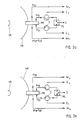
- the structure of the mode coupler (FIG. 1) is identical in its basic structure to the known arrangement cited at the beginning.
- the dimensions of a main waveguide HH are to be chosen so large that all relevant waveguide modes are capable of spreading. However, the dimensions must not be so large that undesirable waveguide modes spread, which can lead to faulty received signals.
- By mode-sensitive coupling of the H10 and H20 wave the field images of FIG. 2a, a sum and a difference diagram (arrow diagram) are obtained in the elevation (FIG. 2b).
- This part of the arrangement is identical to the arrangement described in Skolnik's textbook.
- the H10 mode is coupled out at the end of the waveguide train in a straight line after the main waveguide HH has been gradually reduced to the standard waveguide format, H4.
- the H20 mode is coupled out through a laterally attached waveguide H3.
- the (H11 + E11) wave which provides the difference diagram in azimuth, is transferred in the mode coupler according to the invention in the main waveguide HH with a separating plate B into two antiphase waveguide shafts, as is known in principle from EP-PS 0061 570. Your energy is then selectively coupled with a coupling bracket K in the side-mounted waveguide H2.
- Figures 2c and 2d show the field image and the radiation lobe of the (H11 + E11) wave.
- the mode coupler according to the invention contains coupling openings for decoupling one of the H1on mode orthogonal mode, which is referred to as H01 mode. Its field image and the radiation lobes can be seen in FIGS. 2c and 2d.
- H01 mode is reflected and coupled out into the symmetrical to the main waveguide HH outgoing waveguide H11 and H10 through slots.
- These two waveguides are brought together via an H-level junction HV, so that the performance of the H01 mode can be dissipated in the waveguide H1.
- the waveguide waves of the H10 mode and the H20 mode are not disturbed by the divider B.
- the H10 basic wave type is capable of spreading. They are preferably designed as standard waveguides.
- a metallized dielectric can also be used, on which the coupling structures are produced by etching.
- the simple construction of the mode coupler according to the invention allows production using the electroforming process. This type of production is particularly advantageous for applications at mm wavelengths.
- a pyramid horn or a grooved horn can be easily integrated at the antenna output of the mode coupler, so that the shape and width of the radiation lobes of the antenna feed system can be influenced.
- the version with a grooved horn in particular provides the advantage of identical radiation lobes for the two orthogonal sum modes.
- FIG. 3 shows the possible operating modes of the antenna feed system when using a reflector antenna (main reflector HR, subreflector SR). If the transmit signal S is switched to the H10 gate with the aid of a PIN diode switch PS (the circulators Z serve to decouple the transmit and receive branch), the following signals reflected by the target can be received with the mode coupler MK according to the invention (FIG.
- H10 gate sum signal, portion not rotated in the direction of polarization ( ⁇ ⁇ ) H20 gate, (H11 + E11) gate: difference signals , portions not rotated in the direction of polarization ( ⁇ e ⁇ , ⁇ a ⁇ ) H01 gate: sum signal, portion rotated in the polarization direction by 90 ° ( ⁇ ).
- H10 gate sum signal, portion rotated by 90 ° in the direction of polarization ( ⁇ ).
- H01 gate sum signal, portion not rotated in the polarization direction ( ⁇ ⁇ ).
- both non-polarization-rotating and polarization-rotating targets can be detected and targeted with maximum sensitivity, or conclude from the ratio of the powers in both polarizations to the properties of the target.
- the reflections of undesired targets can be partially suppressed in this way.
- a polarization converter can be provided at the antenna output A of the mode coupler for transmitting and receiving circular polarization.
- This polarization converter must act on all wave types involved and must therefore be arranged as a flat arrangement in front of the mode coupler (e.g. disk made of birefringent material). The advantages of the arrangement described above are retained because, depending on the direction of rotation of the reflected, i.A. elliptically polarized signal can still be distinguished between targets that maintain the direction of rotation of the wave when reflected and those that reverse the direction of rotation.
Landscapes
- Variable-Direction Aerials And Aerial Arrays (AREA)
- Radar Systems Or Details Thereof (AREA)
Applications Claiming Priority (2)
| Application Number | Priority Date | Filing Date | Title |
|---|---|---|---|
| DE3840450A DE3840450A1 (de) | 1988-12-01 | 1988-12-01 | Modenkoppler fuer monopulsanwendungen |
| DE3840450 | 1988-12-01 |
Publications (2)
| Publication Number | Publication Date |
|---|---|
| EP0371494A2 true EP0371494A2 (fr) | 1990-06-06 |
| EP0371494A3 EP0371494A3 (fr) | 1991-06-12 |
Family
ID=6368208
Family Applications (1)
| Application Number | Title | Priority Date | Filing Date |
|---|---|---|---|
| EP19890122043 Withdrawn EP0371494A3 (fr) | 1988-12-01 | 1989-11-29 | Coupleur de modes pour applications monopulsées |
Country Status (3)
| Country | Link |
|---|---|
| US (1) | US5066959A (fr) |
| EP (1) | EP0371494A3 (fr) |
| DE (1) | DE3840450A1 (fr) |
Cited By (2)
| Publication number | Priority date | Publication date | Assignee | Title |
|---|---|---|---|---|
| WO1999066596A1 (fr) * | 1998-06-19 | 1999-12-23 | Raytheon Company | Circuit de reception de radiofrequence |
| US6498582B1 (en) | 1998-06-19 | 2002-12-24 | Raytheon Company | Radio frequency receiving circuit having a passive monopulse comparator |
Families Citing this family (11)
| Publication number | Priority date | Publication date | Assignee | Title |
|---|---|---|---|---|
| US5420597A (en) * | 1991-09-12 | 1995-05-30 | Trw Inc. | Farfield simulator for testing autotrack antennas |
| US5216433A (en) * | 1991-11-15 | 1993-06-01 | Hughes Aircraft Company | Polarimetric antenna |
| DE19810601A1 (de) * | 1998-03-12 | 1999-09-16 | Daimler Benz Aerospace Ag | Anordnung zur Füllstandsmessung |
| US6094175A (en) * | 1998-11-17 | 2000-07-25 | Hughes Electronics Corporation | Omni directional antenna |
| GB9900411D0 (en) * | 1999-01-08 | 1999-02-24 | Cambridge Ind Ltd | Multi-frequency antenna feed |
| FR2808126B1 (fr) * | 2000-04-20 | 2003-10-03 | Cit Alcatel | Element rayonnant hyperfrequence bi-bande |
| US6496084B1 (en) | 2001-08-09 | 2002-12-17 | Andrew Corporation | Split ortho-mode transducer with high isolation between ports |
| JP5580648B2 (ja) * | 2010-04-09 | 2014-08-27 | 古野電気株式会社 | 導波管変換器及びレーダ装置 |
| DE102010063800A1 (de) * | 2010-12-21 | 2012-06-21 | Endress + Hauser Gmbh + Co. Kg | Diplexer für homodynes FMCW-Radargerät |
| CN106935942B (zh) * | 2015-12-30 | 2022-03-18 | 核工业西南物理研究院 | 一种大功率电子回旋共振加热系统快速可控极化器 |
| US11936117B2 (en) | 2019-03-04 | 2024-03-19 | Saab Ab | Dual-band multimode antenna feed |
Family Cites Families (13)
| Publication number | Priority date | Publication date | Assignee | Title |
|---|---|---|---|---|
| US2730677A (en) * | 1952-08-26 | 1956-01-10 | Csf | Ultra-high frequency wave-mode transformers |
| US2820965A (en) * | 1956-02-16 | 1958-01-21 | Itt | Dual polarization antenna |
| DE1930620A1 (de) * | 1968-07-04 | 1970-01-08 | Siemens Ag | Wellentypwandler fuer sehr kurze elektromagnetische Wellen |
| DE2517383C3 (de) * | 1975-04-19 | 1979-03-01 | Licentia Patent-Verwaltungs-Gmbh, 6000 Frankfurt | Systemweiche für Frequenzdoppelausnutzung |
| DE2626925C3 (de) * | 1976-06-16 | 1981-01-08 | Licentia Patent-Verwaltungs-Gmbh, 6000 Frankfurt | Verfahren zum Ausgleich von Ausbreitungsschwankungen bei Nachrichtenübertragungssystemen |
| DE3020514A1 (de) * | 1980-05-30 | 1981-12-10 | Licentia Patent-Verwaltungs-Gmbh, 6000 Frankfurt | Antennenspeisesystem fuer eine nachfuehrbare antenne |
| US4420756A (en) * | 1981-01-19 | 1983-12-13 | Trw Inc. | Multi-mode tracking antenna feed system |
| DE3111731A1 (de) * | 1981-03-25 | 1982-10-14 | Licentia Patent-Verwaltungs-Gmbh, 6000 Frankfurt | Mikrowellenuebertragungseinrichtung mit mehrmodendiversity-kombinationsempfang |
| US4511438A (en) * | 1983-04-05 | 1985-04-16 | Harris Corporation | Bi-metallic electroforming technique |
| DE3406641A1 (de) * | 1984-02-24 | 1985-08-29 | ANT Nachrichtentechnik GmbH, 7150 Backnang | Zweiband-polarisationsweiche |
| GB8501440D0 (en) * | 1985-01-21 | 1985-02-20 | Era Patents Ltd | Circularly polorizing antenna feed |
| DE3604431A1 (de) * | 1986-02-13 | 1987-08-20 | Licentia Gmbh | Modenkoppler fuer monopulsanwendungen |
| DE3604432C2 (de) * | 1986-02-13 | 1995-02-16 | Deutsche Aerospace | Modenkoppler für Monopulsanwendungen |
-
1988
- 1988-12-01 DE DE3840450A patent/DE3840450A1/de not_active Ceased
-
1989
- 1989-11-29 EP EP19890122043 patent/EP0371494A3/fr not_active Withdrawn
- 1989-12-01 US US07/443,955 patent/US5066959A/en not_active Expired - Fee Related
Cited By (3)
| Publication number | Priority date | Publication date | Assignee | Title |
|---|---|---|---|---|
| WO1999066596A1 (fr) * | 1998-06-19 | 1999-12-23 | Raytheon Company | Circuit de reception de radiofrequence |
| US6100841A (en) * | 1998-06-19 | 2000-08-08 | Raytheon Company | Radio frequency receiving circuit |
| US6498582B1 (en) | 1998-06-19 | 2002-12-24 | Raytheon Company | Radio frequency receiving circuit having a passive monopulse comparator |
Also Published As
| Publication number | Publication date |
|---|---|
| EP0371494A3 (fr) | 1991-06-12 |
| US5066959A (en) | 1991-11-19 |
| DE3840450A1 (de) | 1990-06-07 |
Similar Documents
| Publication | Publication Date | Title |
|---|---|---|
| EP0896749B1 (fr) | Ensemble antenne hyperfrequence pour systeme radar de vehicule a moteur | |
| DE69013839T2 (de) | Zwei dielektrische Anpassungsschichten aufweisende Struktur für Radome und Linsen für grosse Einfallswinkel. | |
| EP0061576B1 (fr) | Dispositif de transmission d'informations à micro-ondes avec réception combinée de diversité multimode | |
| DE112004000077B4 (de) | Verdrillter Wellenleiter und drahtlose Vorrichtung | |
| DE69801540T2 (de) | Antennen-Vorrichtung und Radarmodul | |
| DE2727883C2 (de) | Hohlleiterstrahler für links- und rechtsdrehend zirkular polarisierte Mikrowellensignale | |
| DE69731030T2 (de) | Funksendeempfänger | |
| DE69016479T2 (de) | Strahler für zirkular polarisierte Welen mit geringer Kreuzpolarisation. | |
| EP0371494A2 (fr) | Coupleur de modes pour applications monopulsées | |
| DE2311439A1 (de) | Antennenanordnung | |
| DE69010310T2 (de) | Zirkular polarisierte Antenne, insbesondere für Gruppenantenne. | |
| DE2408610B2 (de) | Hornstrahler | |
| DE69121701T2 (de) | Pulsradar und Bauelemente dafür | |
| DE3876862T2 (de) | Mikrowellenprimaersende- und empfangsduplexer fuer orthogonalpolarisierte wellen. | |
| DE3786664T2 (de) | Mikrowellenerreger für orthogonal polarisierte wellen. | |
| DE69314834T2 (de) | Zirkular polarisierte Mikrowellenantenne | |
| DE1107736B (de) | Hornstrahler mit rechteckigem Querschnitt fuer Mikrowellen | |
| DE69721452T2 (de) | Kombinierter Duplexer-Mischer | |
| DE69415618T2 (de) | Zirkular-Linearpolarisator | |
| EP0422431B1 (fr) | Dispositif à diversité angulaire | |
| DE3604432C2 (de) | Modenkoppler für Monopulsanwendungen | |
| WO1999004282A1 (fr) | Dispositif pour emettre et recevoir des ondes radar, notamment pour un capteur de distance | |
| DE951732C (de) | Ultrakurzwellen-UEbertragungssystem mit wenigstens zwei UEbertragungskanaelen | |
| DE3604431A1 (de) | Modenkoppler fuer monopulsanwendungen | |
| DE3615502C2 (de) | Entkopplungsanordnung für Dauerstrich-Radare |
Legal Events
| Date | Code | Title | Description |
|---|---|---|---|
| PUAI | Public reference made under article 153(3) epc to a published international application that has entered the european phase |
Free format text: ORIGINAL CODE: 0009012 |
|
| AK | Designated contracting states |
Kind code of ref document: A2 Designated state(s): DE FR GB |
|
| PUAL | Search report despatched |
Free format text: ORIGINAL CODE: 0009013 |
|
| AK | Designated contracting states |
Kind code of ref document: A3 Designated state(s): DE FR GB |
|
| 17P | Request for examination filed |
Effective date: 19911121 |
|
| RAP1 | Party data changed (applicant data changed or rights of an application transferred) |
Owner name: TELEFUNKEN SYSTEMTECHNIK AG |
|
| RAP1 | Party data changed (applicant data changed or rights of an application transferred) |
Owner name: DEUTSCHE AEROSPACE AKTIENGESELLSCHAFT |
|
| RBV | Designated contracting states (corrected) |
Designated state(s): DE |
|
| STAA | Information on the status of an ep patent application or granted ep patent |
Free format text: STATUS: THE APPLICATION HAS BEEN WITHDRAWN |
|
| 18W | Application withdrawn |
Withdrawal date: 19930508 |