EP0371729A2 - Verbesserungen an Stühlen - Google Patents
Verbesserungen an Stühlen Download PDFInfo
- Publication number
- EP0371729A2 EP0371729A2 EP19890312290 EP89312290A EP0371729A2 EP 0371729 A2 EP0371729 A2 EP 0371729A2 EP 19890312290 EP19890312290 EP 19890312290 EP 89312290 A EP89312290 A EP 89312290A EP 0371729 A2 EP0371729 A2 EP 0371729A2
- Authority
- EP
- European Patent Office
- Prior art keywords
- seat
- chair
- user
- angle
- line
- Prior art date
- Legal status (The legal status is an assumption and is not a legal conclusion. Google has not performed a legal analysis and makes no representation as to the accuracy of the status listed.)
- Granted
Links
- 229910000831 Steel Inorganic materials 0.000 description 1
- 230000006835 compression Effects 0.000 description 1
- 238000007906 compression Methods 0.000 description 1
- 230000000994 depressogenic effect Effects 0.000 description 1
- 210000003414 extremity Anatomy 0.000 description 1
- 210000002414 leg Anatomy 0.000 description 1
- 230000004048 modification Effects 0.000 description 1
- 238000012986 modification Methods 0.000 description 1
- 239000010959 steel Substances 0.000 description 1
- 210000000689 upper leg Anatomy 0.000 description 1
- 238000003466 welding Methods 0.000 description 1
Images



Classifications
-
- A—HUMAN NECESSITIES
- A47—FURNITURE; DOMESTIC ARTICLES OR APPLIANCES; COFFEE MILLS; SPICE MILLS; SUCTION CLEANERS IN GENERAL
- A47C—CHAIRS; SOFAS; BEDS
- A47C3/00—Chairs characterised by structural features; Chairs or stools with rotatable or vertically-adjustable seats
- A47C3/20—Chairs or stools with vertically-adjustable seats
- A47C3/28—Chairs or stools with vertically-adjustable seats with clamps acting on vertical rods
-
- A—HUMAN NECESSITIES
- A47—FURNITURE; DOMESTIC ARTICLES OR APPLIANCES; COFFEE MILLS; SPICE MILLS; SUCTION CLEANERS IN GENERAL
- A47C—CHAIRS; SOFAS; BEDS
- A47C9/00—Stools for specified purposes
- A47C9/02—Office stools; Workshop stools
- A47C9/025—Stools for standing or leaning against, e.g. in a semi-standing or half-seated position
Definitions
- the present invention relates to chairs and more particularly to chairs designed to be able to support the body of a human being (the user) at one or more heights.
- Chairs are normally designed to support a user in a sitting position even through the height at which the user sits can be adjusted to suit users of different heights.
- Known adjustment systems comprise spring loaded central support columns or gas filled cylinder systems controlled by a lever adjacent the chair seat.
- a chair for supporting a user in a sitting or semi-standing position including a seat, the seat providing a substantially horizontal uppermost surface for the user irrespective of the angle at which the seat is set. If cushioned the actual upper surface may be curved when not in use.
- the horizontal surface comprises at least a thin line running transversely on the seat surface forming the highest portion of the seat, this line lying in a vertical plane passing through a base structure of the chair.
- this line in a preferred embodiment, remains substantially in the same vertical plane relative to the base of the chair.
- a chair 10 is shown diagrammatically.
- the chair comprises three basis component parts, a base 20, a seat 30 and a backrest 40 (if provided).
- the base 20 may be of the star or similar known type providing a stable base providing that the weight on the chair is within the area of the base.
- the backrest 40 (if fitted) may be attached to the seat in known manner.
- the seat 30 has an upper curved surface 32 and may be adjusted or set at a number of angles as shown by dotted lines 321, 322.
- Dotted line 321 is suitable for a higher position of the chair corresponding to a stand position for the user and dotted line 322 is suitable for a lower for the chair corresponding to a sitting position for the user.
- the highest “point” on the surface of the seat shown diagrammatically at 323 is shown on the vertical dotted line 324.
- the highest “point” of the seat will in the seat design according to the present invention still remain substantially on the line 324.
- the seats shown in Figures 2 to 7 are specifically designed such that there is always an uppermost horizontal portion of the seat X-X to be sat on by the user for support at all heights within the designed height range.
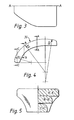
- the shape of seat 30 is shown in Figures 2 to 5 and with reference to Figure 4 the seat is contoured to provide an upper surface 31 the shape of which is dictated by three arcs of radii R1, R2 and R3 as shown.
- the seat is shaped to be narrower at the front as indicated by the cross-sectional shapes A′-A′, B′-B′ and C′-C′ shown in Figure 5 and by the plan view of Figure 3.
- the seat shape could, however, be of the more conventional substantially rectangular shape as indicated by the dotted lines.
- the upper surface 31 of the seat need not necessarily be flat to form a completely horizontal surface but could be contoured by suitable upholstery to provide for example a domed shape which may be more comfortable or a seat contoured to accommodate the shape of the upper legs or thighs.
- the seat may be provided for example with a tensioned net or canvas sling stretched over a suitable frame.
- the dimensions of the radii R1, R2 and R3 are as follows:- R1 - 140 mm R2 - 280 mm R3 - 350 mm
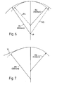
- FIG. 6 a simpler contour for the seat is shown comprising two arcs of radii R4 and R5 as shown.
- Radius R4 is the shorter and is used as indicated by the solid line to form the back of the seat and R5 is the longer and is used to form the front of the seat as shown by the solid line.
- the dotted continuation lines of arc are only shown to illustrate the differences in the radii.
- the seat is pivoted about point P to achieve the desired property of maintaining an uppermost horizontal line X-X to sit on at all angles of pivot of the seat.
- FIG. 7 A modification of the seat contour of Figure 6 is shown in Figure 7, the radius R5 being replaced by a tangential shape as indicated by the straight line R, radius R5 being shown dotted for comparison.
- the seat shapes shown may be set at fixed angles for various types of seat and they will always provide an uppermost substantially horizontal line X-X for the user to sit on. In practise this line will, in an upholstered or padded seat provide a generally horizontal platform sloping at its extremities both to the back and the front of the seat. Thus the user will not be unbalanced on the seat since there there will be no tendency to slide to the front or back of the seat. This is particularly advantageous since any such tendency is always resisted by a user causing strain.
- the seat design according to the present invention is therefore comfortable to sit on at all heights at which is it set. Thus for example for laboratory stools the seat can be set for a high level use and for typing chairs it can be set at a low lever.
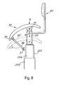
- Figure 8 the upper part of a chair is shown and comprises the seat 30 pivoted on a pivot 35 attached to a main support member 25.
- a first height adjustment is provided by for example a gas filled cylinder 200. This is used to adjust the seat for the height of the user for example at the lowest or sitting position by altering the height of ram 202. Once set for a particular user this cylinder 200 would not be further altered.
- a further cylinder 204 is positioned within ram 202 to provide further vertical movement of seat 30.
- cylinder 204 is activated by means of for example of a lever in known manner to allow main support member 25 to move upwardly under the force of the cylinder or downwardly under the weight of the user on the seat 30.
- member 25 moves into or out of cylinder 204 so seat 30 is moved by an arm 36 connected in a pivotal manner between ram 202 and the front of the seat at pivot points 37, 38.
- the seat 30 will therefore move as indicated by dotted outline 30′.
- Line X-X (as indicated by the arrow X) will as shown always be at the highest point on the seat and in this embodiment this line is vertically above the main support member 25 providing the most suitable condition for the seat.
- a manual adjustment could be provided by a suitable screw clamp on pivot 35 allowing the seat to be rotated to suit the user.
- Line X-X will however always be the highest portion of the seat.
- the chair 100 comprises a base 1200 which may be of the conventional three or five star configuration. In the drawing only two feet 1202, 1204 are shown for simplicity of drawing.
- a first main support member 1206 is fixed; for example by welding into the base 1200 and a second main support member 1208 is slidably mounted over the first member 1206 as shown.
- each support member 1206, 1208 comprises a steel tube of circular cross section.
- Support member 1208 is movable vertically relative to support member 1206 by means of a spring 1210 (which in a practical chair would be provided with a cover 1212 shown as a dotted line).
- the two members are normally locked together by a locking arrangement 1214, 1216 which operates in known manner to allow relative movement between the members on compression of a spring 1218. This is achieved by a downward movement of operating rod 1220 by downward operation of a lever 1222 which is situated under the front of seat 30 ( Figure 1). This movement is well known in such chair designs and will not therefore be described in any greater detail.
- the lift provided for the chair seat by this arrangement is in the chair shown 120 mm (approx. 5 inches) which accomodates for the sitting position height range. It is noted here that the angle of the seat 30 does not change due to operation of lever 1222.
- the seat 30 is pivotally supported on a pin 1224 and tilting of the seat is accomplished by the pivotal connection of the front of the seat to a lever 1226 on a pivot pin 1228.
- the seat is supported on a platform 1230 which is mounted on a bearing 1232 which enables the seat to be revolved.
- the seat 30 may be raised by operation of a lever 1234 into the position shown partially at 301 and 12261.
- the lever 1234 operates when depressed to release the piston 1236 and allow the seat to rise (in known manner) under the pressure provided by either a pneumatic pressure or by a further spring (not shown).
- the seat may be lowered by operating the lever 1234 and pressing down on the top of the seat.
- the operation of the seat may be clearly seen by the two positions 30, 1226 and 301, 12261.
- the piston 1236 rises the upper portion 1240 of the platform 1230 rises relative to the base portion 1242 to which the opposite end of lever 1226 is pivotally connected at pivot point 1244.
- the seat rises the angle of the seat is tilted gradually, the seat always having a horizontal portion to support the user.
- a backrest 1246, 1248 is also attached to the upper part 1240 of the platform 1230 so that the backrest rises with the seat.
Landscapes
- Chairs Characterized By Structure (AREA)
- Chair Legs, Seat Parts, And Backrests (AREA)
- Special Chairs (AREA)
Applications Claiming Priority (2)
| Application Number | Priority Date | Filing Date | Title |
|---|---|---|---|
| GB888827846A GB8827846D0 (en) | 1988-11-29 | 1988-11-29 | Improvements in/relating to chairs |
| GB8827846 | 1988-11-29 |
Publications (3)
| Publication Number | Publication Date |
|---|---|
| EP0371729A2 true EP0371729A2 (de) | 1990-06-06 |
| EP0371729A3 EP0371729A3 (en) | 1990-08-22 |
| EP0371729B1 EP0371729B1 (de) | 1994-10-19 |
Family
ID=10647648
Family Applications (1)
| Application Number | Title | Priority Date | Filing Date |
|---|---|---|---|
| EP19890312290 Expired - Lifetime EP0371729B1 (de) | 1988-11-29 | 1989-11-27 | Verbesserungen an Stühlen |
Country Status (5)
| Country | Link |
|---|---|
| EP (1) | EP0371729B1 (de) |
| CA (1) | CA2004002C (de) |
| DE (1) | DE68918921T2 (de) |
| ES (1) | ES2064464T3 (de) |
| GB (2) | GB8827846D0 (de) |
Cited By (1)
| Publication number | Priority date | Publication date | Assignee | Title |
|---|---|---|---|---|
| CN106175230A (zh) * | 2016-07-01 | 2016-12-07 | 卓达新材料科技集团威海股份有限公司 | 斜面靠椅 |
Families Citing this family (7)
| Publication number | Priority date | Publication date | Assignee | Title |
|---|---|---|---|---|
| GB9107661D0 (en) * | 1991-04-11 | 1991-05-29 | Nat Res Dev | Adjustable chair |
| GB2354434A (en) * | 1999-09-20 | 2001-03-28 | Benjamin Jasper Dobson | Compression relief seat for persons |
| DE10007103B4 (de) | 2000-02-16 | 2004-01-29 | Wolfgang Deisig | Verstellbarer Arbeitsstuhl, insbesondere Bürostuhl |
| GB2483876A (en) * | 2010-09-22 | 2012-03-28 | Nicholas David Le Sueur | Seat height adjustment mechanism |
| GB201110748D0 (en) | 2011-06-24 | 2011-08-10 | Freedman Simon A | A seat |
| DE202018100807U1 (de) | 2018-02-14 | 2018-04-03 | Kinema Gmbh | Sitz- und Stützmöbel |
| DE102018103322A1 (de) * | 2018-02-14 | 2019-08-14 | Kinema Gmbh | Sitz- und Stützmöbel |
Family Cites Families (5)
| Publication number | Priority date | Publication date | Assignee | Title |
|---|---|---|---|---|
| US4529247A (en) * | 1982-04-15 | 1985-07-16 | Herman Miller, Inc. | One-piece shell chair |
| FR2552988B1 (fr) * | 1983-10-10 | 1986-03-21 | Savigny Francois | Siege polyvalent donnant une station mi-assise, mi-a genoux |
| US4552404A (en) * | 1983-10-12 | 1985-11-12 | Congleton Jerome J | Neutral body posture chair |
| SE449688B (sv) * | 1984-10-17 | 1987-05-18 | Liedberg Ostlund Ab | Arbetsstol med svengbart ryggstod |
| GB2205737B (en) * | 1987-05-23 | 1991-04-03 | Nat Res Dev | Improvements in or relating to chairs |
-
1988
- 1988-11-29 GB GB888827846A patent/GB8827846D0/en active Pending
-
1989
- 1989-11-27 GB GB8926725A patent/GB2226756B/en not_active Expired - Lifetime
- 1989-11-27 ES ES89312290T patent/ES2064464T3/es not_active Expired - Lifetime
- 1989-11-27 EP EP19890312290 patent/EP0371729B1/de not_active Expired - Lifetime
- 1989-11-27 DE DE1989618921 patent/DE68918921T2/de not_active Expired - Fee Related
- 1989-11-28 CA CA 2004002 patent/CA2004002C/en not_active Expired - Fee Related
Cited By (1)
| Publication number | Priority date | Publication date | Assignee | Title |
|---|---|---|---|---|
| CN106175230A (zh) * | 2016-07-01 | 2016-12-07 | 卓达新材料科技集团威海股份有限公司 | 斜面靠椅 |
Also Published As
| Publication number | Publication date |
|---|---|
| EP0371729B1 (de) | 1994-10-19 |
| GB2226756A (en) | 1990-07-11 |
| GB8926725D0 (en) | 1990-01-17 |
| DE68918921T2 (de) | 1995-02-23 |
| ES2064464T3 (es) | 1995-02-01 |
| GB2226756B (en) | 1992-09-02 |
| DE68918921D1 (de) | 1994-11-24 |
| EP0371729A3 (en) | 1990-08-22 |
| CA2004002A1 (en) | 1990-05-29 |
| GB8827846D0 (en) | 1988-12-29 |
| CA2004002C (en) | 1999-06-22 |
Similar Documents
| Publication | Publication Date | Title |
|---|---|---|
| US5253922A (en) | Chair adjustable in height providing a weight bearing surface at any height, and having a seat that rotates so as to change its angle of inclination | |
| US5054857A (en) | Convertible chair | |
| US5009466A (en) | Reclining chair | |
| US7585028B2 (en) | Mobile ergonomic rotating adjustable chair with lumbar support | |
| US8944507B2 (en) | Ergonomic adjustable chair mechanisms | |
| US6752459B2 (en) | Adjustable chair | |
| US4007962A (en) | Chair with adjustable back | |
| JP3255592B2 (ja) | 背もたれおよび座席の調整が連動している、腰掛け用家具部材、および接続補強材 | |
| CA2302063C (en) | Ergonomic chair | |
| US7484803B2 (en) | Chair, especially and office or work chair | |
| US6578918B1 (en) | Chair | |
| US5370445A (en) | Chair control | |
| EP0371729B1 (de) | Verbesserungen an Stühlen | |
| US5390979A (en) | Adjustable chair | |
| CA2379873C (en) | Chair | |
| US11690455B2 (en) | Synchronous-tilt reclining chair | |
| JP3780803B2 (ja) | 椅子 | |
| AU721284B3 (en) | Underarmpit support chair | |
| JPH01124406A (ja) | 椅子の傾動装置 | |
| HK1188695A (en) | Ergonomic adjustable chair mechanisms | |
| HK1087900B (en) | Chair |
Legal Events
| Date | Code | Title | Description |
|---|---|---|---|
| PUAI | Public reference made under article 153(3) epc to a published international application that has entered the european phase |
Free format text: ORIGINAL CODE: 0009012 |
|
| AK | Designated contracting states |
Kind code of ref document: A2 Designated state(s): BE DE ES FR GB IT SE |
|
| PUAL | Search report despatched |
Free format text: ORIGINAL CODE: 0009013 |
|
| 17P | Request for examination filed |
Effective date: 19900613 |
|
| AK | Designated contracting states |
Kind code of ref document: A3 Designated state(s): BE DE ES FR GB IT SE |
|
| 17Q | First examination report despatched |
Effective date: 19920128 |
|
| RAP1 | Party data changed (applicant data changed or rights of an application transferred) |
Owner name: BRITISH TECHNOLOGY GROUP PLC |
|
| RAP3 | Party data changed (applicant data changed or rights of an application transferred) |
Owner name: BRITISH TECHNOLOGY GROUP LTD |
|
| GRAA | (expected) grant |
Free format text: ORIGINAL CODE: 0009210 |
|
| AK | Designated contracting states |
Kind code of ref document: B1 Designated state(s): BE DE ES FR GB IT SE |
|
| ITF | It: translation for a ep patent filed | ||
| ET | Fr: translation filed | ||
| REF | Corresponds to: |
Ref document number: 68918921 Country of ref document: DE Date of ref document: 19941124 |
|
| EAL | Se: european patent in force in sweden |
Ref document number: 89312290.3 |
|
| REG | Reference to a national code |
Ref country code: ES Ref legal event code: FG2A Ref document number: 2064464 Country of ref document: ES Kind code of ref document: T3 |
|
| PLBE | No opposition filed within time limit |
Free format text: ORIGINAL CODE: 0009261 |
|
| STAA | Information on the status of an ep patent application or granted ep patent |
Free format text: STATUS: NO OPPOSITION FILED WITHIN TIME LIMIT |
|
| 26N | No opposition filed | ||
| PGFP | Annual fee paid to national office [announced via postgrant information from national office to epo] |
Ref country code: ES Payment date: 19961115 Year of fee payment: 8 |
|
| PGFP | Annual fee paid to national office [announced via postgrant information from national office to epo] |
Ref country code: BE Payment date: 19961128 Year of fee payment: 8 |
|
| PG25 | Lapsed in a contracting state [announced via postgrant information from national office to epo] |
Ref country code: ES Free format text: LAPSE BECAUSE OF NON-PAYMENT OF DUE FEES Effective date: 19971128 |
|
| PG25 | Lapsed in a contracting state [announced via postgrant information from national office to epo] |
Ref country code: BE Free format text: LAPSE BECAUSE OF NON-PAYMENT OF DUE FEES Effective date: 19971130 |
|
| BERE | Be: lapsed |
Owner name: BRITISH TECHNOLOGY GROUP LTD Effective date: 19971130 |
|
| REG | Reference to a national code |
Ref country code: GB Ref legal event code: 732E |
|
| REG | Reference to a national code |
Ref country code: GB Ref legal event code: IF02 |
|
| REG | Reference to a national code |
Ref country code: ES Ref legal event code: FD2A Effective date: 19981212 |
|
| PGFP | Annual fee paid to national office [announced via postgrant information from national office to epo] |
Ref country code: SE Payment date: 20051109 Year of fee payment: 17 Ref country code: DE Payment date: 20051109 Year of fee payment: 17 |
|
| PGFP | Annual fee paid to national office [announced via postgrant information from national office to epo] |
Ref country code: FR Payment date: 20051114 Year of fee payment: 17 |
|
| PG25 | Lapsed in a contracting state [announced via postgrant information from national office to epo] |
Ref country code: SE Free format text: LAPSE BECAUSE OF NON-PAYMENT OF DUE FEES Effective date: 20061128 |
|
| PGFP | Annual fee paid to national office [announced via postgrant information from national office to epo] |
Ref country code: IT Payment date: 20061130 Year of fee payment: 18 |
|
| PG25 | Lapsed in a contracting state [announced via postgrant information from national office to epo] |
Ref country code: DE Free format text: LAPSE BECAUSE OF NON-PAYMENT OF DUE FEES Effective date: 20070601 |
|
| EUG | Se: european patent has lapsed | ||
| REG | Reference to a national code |
Ref country code: FR Ref legal event code: ST Effective date: 20070731 |
|
| PG25 | Lapsed in a contracting state [announced via postgrant information from national office to epo] |
Ref country code: FR Free format text: LAPSE BECAUSE OF NON-PAYMENT OF DUE FEES Effective date: 20061130 |
|
| PGFP | Annual fee paid to national office [announced via postgrant information from national office to epo] |
Ref country code: GB Payment date: 20081222 Year of fee payment: 20 |
|
| PG25 | Lapsed in a contracting state [announced via postgrant information from national office to epo] |
Ref country code: IT Free format text: LAPSE BECAUSE OF NON-PAYMENT OF DUE FEES Effective date: 20071127 |
|
| REG | Reference to a national code |
Ref country code: GB Ref legal event code: PE20 Expiry date: 20091126 |
|
| PG25 | Lapsed in a contracting state [announced via postgrant information from national office to epo] |
Ref country code: GB Free format text: LAPSE BECAUSE OF EXPIRATION OF PROTECTION Effective date: 20091126 |