EP0372240A2 - Détecteur de passage par zéro pour systèmes polyphasés - Google Patents
Détecteur de passage par zéro pour systèmes polyphasés Download PDFInfo
- Publication number
- EP0372240A2 EP0372240A2 EP89120598A EP89120598A EP0372240A2 EP 0372240 A2 EP0372240 A2 EP 0372240A2 EP 89120598 A EP89120598 A EP 89120598A EP 89120598 A EP89120598 A EP 89120598A EP 0372240 A2 EP0372240 A2 EP 0372240A2
- Authority
- EP
- European Patent Office
- Prior art keywords
- phase
- voltage
- output
- input
- measured voltage
- Prior art date
- Legal status (The legal status is an assumption and is not a legal conclusion. Google has not performed a legal analysis and makes no representation as to the accuracy of the status listed.)
- Granted
Links
- 238000005259 measurement Methods 0.000 claims abstract description 15
- 238000000034 method Methods 0.000 claims description 2
- 238000010586 diagram Methods 0.000 description 12
- 230000007704 transition Effects 0.000 description 7
- 238000012544 monitoring process Methods 0.000 description 4
- 230000001934 delay Effects 0.000 description 1
- 238000001514 detection method Methods 0.000 description 1
- 238000006073 displacement reaction Methods 0.000 description 1
- 230000007935 neutral effect Effects 0.000 description 1
- 238000005191 phase separation Methods 0.000 description 1
- 238000010248 power generation Methods 0.000 description 1
Images




Classifications
-
- G—PHYSICS
- G01—MEASURING; TESTING
- G01R—MEASURING ELECTRIC VARIABLES; MEASURING MAGNETIC VARIABLES
- G01R19/00—Arrangements for measuring currents or voltages or for indicating presence or sign thereof
- G01R19/175—Indicating the instants of passage of current or voltage through a given value, e.g. passage through zero
Definitions
- the invention disclosed broadly relates to the switching of multiphase electrical power sources and more particularly relates to the precise identification of zero crossover for the relative phases in a polyphase system.
- Delta power systems and some unreferenced wye power systems are commonly used in power generation and distribution networks. These are three phase voltage systems, the waveform of which is shown in Fig. 1. Conventionally, three phase voltage waveforms are represented by phase A, phase B and phase C which are generated so as to be 120 degrees in phase separation, respectively. The measurement of the relative timing is generated at the respective phases crossing zero volts is important in power switching control applications. For example, reference is made to the U. S. patent 4,761,563 to Ross and Woodworth, entitled “Asynchronous Multiphase Switching Gear,” wherein Fig.
- FIG. 28 shows a waveform coincidence detector circuit which requires the detection of the zero crossover for each respective phase A, B and C, in order to carry out the operation of synchronously transferring three phase power from a first power source to a second power source.
- This is just one example of many which could be provided of the need to identify when the phases cross zero volts. Proper phasing and control of electronic switching devices often rely on this timing information.
- the actual passage of a phase through zero cannot be recorded accurately at times due to power line noise.
- the displacement of the imaginary neutral voltage reference point from ground due to unbalanced ground currents and system switching delays cause significant errors. This can be better understood with reference to the vectorial representation of a three phase power system, as is shown in Fig. 2.
- FIG. 2 illustrates a vectorial representation of the three phases A, B and C as an equilateral triangle. It is seen in the six views of the vectorial triangle in Fig. 2, that the triangle appears to be rotating in a clockwise direction. This represents each of a 60 degree increment in the rotation of the three phase generator supplying the power to the three phase system.
- the geometry of the three phase waveforms as shown in Fig. 2 can be described as follows. In a three phase alternating current (AC) system, one phase, for example phase A, will cross through an imaginary zero voltage point when the other two phase voltages, for example B and C phases, are equal and opposite in magnitude. This can be seen in the diagram of Fig.
- AC alternating current
- FIG. 2 which shows the vectorial representation of a three phase power system and occurs twice per phase in a full revolution of the three phase generator.
- the crossings occur at both the negative to positive and at the positive to negative polarity crossings.
- Fig. 2 has six views labeled 1 through 6.
- view 1 a positive going crossing is illustrated for the A phase.
- view 2 a negative going crossing is illustrated for the B phase.
- view 3 a positive going crossing is illustrated for the C phase.
- a negative going crossing is illustrated for the A phase.
- a positive going crossing is illustrated for the B phase.
- a negative going crossing is illustrated for the C phase.
- the prior art has not provided a reliable, noise tolerant technique for identifying the zero crossing of the respective phases of a polyphase power system. It is therefore an object of the invention to provide an improved means to identify the zero phase crossing of the phases in a polyphase power system.
- the invention finds application primarily in three phase power systems having A, B and C voltage phases.
- the invention includes a first voltage measurement device coupled between the A phase input and the B phase input, having a first measured voltage output.
- the invention further includes a second voltage measurement device coupled between the A phase input and the C phase input, having a second measured voltage output.
- the invention also includes a comparator having a first input connected to the first output of the first voltage measurement device and a second input connected to the second output of the second voltage measurement device, for generating a signal when the first measured voltage is equal to and opposite in polarity from the second measured voltage. This signal indicates that a zero crossover event has occurred with the A phase.
- Fig. 3 illustrates a circuit schematic diagram of the zero voltage crossover detector for a three phase system. Illustrated in the figure is a three phase alternator which includes the coils 20, 20′ and 20 ⁇ . Coil 20 is connected between the A and C phases. Coil 20′ is connected between the C and B phases. Coil 20 ⁇ is connected between the A and B phases.
- a first voltage measurement device 22 has its inputs connected between the phase A and the phase B and serves to measure the voltage or potential difference between the phases A and B and it outputs that measured voltage output as a first value.
- a second voltage measuring device 24 is shown in Fig. 3 connected between the phase A and the phase C and it serves to measure the potential difference between A and C and provides that measured voltage output as a second measured value.
- a comparator 26 has a first input connected to the output of the first voltage measuring device 22 and a second input connected to the output of the second voltage measuring device 24, for generating a signal when the first measured voltage value from measuring device 22 is equal in magnitude and opposite in polarity from the second measured voltage value from the output of the measuring device 24. The presence of this signal indicates the zero crossover event has occurred for the A phase.
- Fig. 4 is a waveform diagram illustrating the operation of the invention shown in Fig. 3. Shown in Fig. 4 is a graph with voltage as the ordinate and time as the abscissa, illustrating the voltage waveform for the C phase and the inverse (-B) waveform for the B phase. It is seen that when the C phase voltage is equal in magnitude and opposite in polarity to the B phase voltage, that a transition is shown in the solid line shown in the graph of Fig. 4, which is the signal representing the zero crossover event for the A phase. It is seen that the zero crossover event for the A phase occurs twice per each revolution of the alternator in Fig. 3.
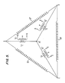
- Fig. 5 is a circuit schematic diagram illustrating how three transformers T1, T2 and T3 can serve as three voltage measuring devices for measuring the zero crossover event for the three phases A, B and C. Shown in Fig. 3 is the alternator circuit with the coils 20, 20′ and 20 ⁇ illustrated in Fig. 5. Also shown is a connection of the primary coils T1′, T2′ and T3′ so that the coils each have one end connected to one of the respective terminals A, B and C and each respective primary coil has its other end connected in common so that all three primary coils have one end connected in common.
- Each transformer T1, T2 and T3 has its secondary coil T1 ⁇ , T2 ⁇ and T3 ⁇ , respectively, as a center tapped secondary coil which has its respective opposed ends labeled a, a*, b, b* and c, c*, respectively.
- the connection of the transformers T1, T2 and T3 shown in Fig. 5 so as to perform the operation of voltage measuring devices is shown with greater detail in the circuit schematic diagram of Fig. 6.
- Fig. 6 it is seen that the A phase, the B phase and the C phase are input to the primary coils of T1, T2 and T3 and that the common terminal 25 is shown for the primary coils for these three transformers.
- the secondary coils T1 ⁇ , T2 ⁇ and T3 ⁇ are shown as they are connected to the balance of the circuit in Fig. 6.
- Fig. 6 there is shown that a zero crossover leg for the A phase which will serve as the initial example of the circuit in Fig. 6.
- the transformer T2 has its secondary coil T2 ⁇ connected with the -b voltage connected to the positive input of a first buffer amplifier 30 and the center tap connected to a ground potential.
- the transformer T3 has its secondary T3 ⁇ with the positive c terminal connected to the positive terminal of a second buffer amplifier 30′ and its center tap connected to ground potential.
- the output of the first comparator 30 is applied to the positive input of the comparator 32 and the output of the buffer amplifier 30′ is connected to the negative input of the comparator 32.
- the function of the comparator 32 is to determine when the output of the buffer amplifier 30 is equal in magnitude and opposite in polarity from the output of the buffer amplifier 30′. At the instant when that relationship occurs, the comparator 32 outputs a signal which indicates the zero crossover event for the A phase.
- the particular operation of the circuit of Fig. 6 is shown in Fig. 7, where it is seen that the output of the comparator 32 is a transition from a positive 5 volt level to a negative approximate 13 volt level.
- That transition direction indicates that the A phase is undergoing a positive to negative transition and the time of occurrence of the transition is the time of occurrence of the zero crossing for the A phase. If the output of the comparator 32 is transitioned from -14 volts to +5 volts, this indicates that the A phase transition is made from a negative to a positive value in the occurrence of the zero crossover event.
- the output of the comparator 32 is applied to the input as a single shot circuit 34 which generates a small square wave pulse indicating the instant of occurrence of the transition shown at the output of the comparator 32.
- the output of the single shot 34 can be used as a binary value signal which can be applied to utilization circuits such as the waveform coincidence detector circuit of the Ross and Woodworth patent, described above and as is seen in Fig. 8 herein.
- each respective zero crossover phase is identified by means of a particular monitoring leg, the A phase leg having been described above.
- the B phase leg consists of a buffer amplifier 30b and 30b′ whose outputs are applied to the input of a character 32b.
- the output of the comparator 32b is then applied to a single shot 34b which provides a binary signal output which can be applied to utilization logic.
- the C phase monitoring leg includes the buffer amplifier 30C and 30c′.
- the outputs of the buffer amplifier 30c and 30c′ are applied to the inputs of the comparator 32c.
- the output of the comparator 32c can be applied to a single shot 34c.
- the output of the single shot 34c will be a binary value which can be applied in logic utilization circuits.
- the comparator 30b has its positive input terminal connected to the secondary T3 ⁇ , and to its negative c terminal and that the buffer amplifier 30b and the buffer amplifier 30b′ has its positive input terminal connected to the +a terminal of the secondary T1 ⁇ .
- the buffer amplifier 30c has its positive input terminal connected to the negative a terminal of the T1 ⁇ secondary and that the buffer amplifier 30c′ has its positive terminal connected to the +b terminal of the T2 ⁇ secondary.
- the operation of the invention provides a noise tolerant zero voltage crossover detector for all three phases of a three phase power system.
Landscapes
- Physics & Mathematics (AREA)
- General Physics & Mathematics (AREA)
- Measurement Of Current Or Voltage (AREA)
- Testing Of Short-Circuits, Discontinuities, Leakage, Or Incorrect Line Connections (AREA)
- Measuring Phase Differences (AREA)
Applications Claiming Priority (2)
| Application Number | Priority Date | Filing Date | Title |
|---|---|---|---|
| US280470 | 1988-12-05 | ||
| US07/280,470 US4901005A (en) | 1988-12-05 | 1988-12-05 | Zero voltage crossover detector for polyphase systems |
Publications (3)
| Publication Number | Publication Date |
|---|---|
| EP0372240A2 true EP0372240A2 (fr) | 1990-06-13 |
| EP0372240A3 EP0372240A3 (fr) | 1991-06-26 |
| EP0372240B1 EP0372240B1 (fr) | 1994-03-02 |
Family
ID=23073227
Family Applications (1)
| Application Number | Title | Priority Date | Filing Date |
|---|---|---|---|
| EP89120598A Expired - Lifetime EP0372240B1 (fr) | 1988-12-05 | 1989-11-07 | Détecteur de passage par zéro pour systèmes polyphasés |
Country Status (5)
| Country | Link |
|---|---|
| US (1) | US4901005A (fr) |
| EP (1) | EP0372240B1 (fr) |
| JP (1) | JPH06105267B2 (fr) |
| CA (1) | CA2004340C (fr) |
| DE (1) | DE68913450T2 (fr) |
Families Citing this family (16)
| Publication number | Priority date | Publication date | Assignee | Title |
|---|---|---|---|---|
| US5179495A (en) * | 1990-08-02 | 1993-01-12 | Furnas Electric Company | Solid state overload relay |
| US5212407A (en) * | 1990-10-04 | 1993-05-18 | International Business Machines Corporation | Digital phase match discriminator for three-phase power |
| KR960003360B1 (ko) * | 1991-06-03 | 1996-03-09 | 마쯔시다덴기산교 가부시기가이샤 | 영상전압측정장치 |
| US5319304A (en) * | 1992-05-01 | 1994-06-07 | General Electric Company | Device for monitoring load |
| US5578928A (en) * | 1995-01-23 | 1996-11-26 | General Electric Company | Method for detecting zero crossings in a rectified power signal |
| US5548207A (en) * | 1995-05-08 | 1996-08-20 | Magl Power Inc. | Missing phase detector |
| US6112159A (en) * | 1996-08-01 | 2000-08-29 | Siemens Power Transmission & Distribution, Llc | Robust electrical utility meter |
| DE19631807C1 (de) * | 1996-08-07 | 1997-08-28 | Beha C Gmbh | Verfahren zur Bestimmung der Drehfeldrichtung in einem Dreiphasennetz (Drehstromnetz) |
| DE19653323C2 (de) * | 1996-12-20 | 2001-07-12 | Beha C Gmbh | Vorrichtung zur Bestimmung des Vorzeichens einer Phasenverschiebung zweier elektrischer Signale |
| US6696968B2 (en) * | 2001-02-28 | 2004-02-24 | Josette Tari | Visualization luminous device adapted for electric motors of equipments supplied by the three-phase voltage |
| US6717395B2 (en) | 2001-05-31 | 2004-04-06 | Mcgraw-Edison Company | Current transformer based high voltage measurement apparatus |
| US6529013B2 (en) | 2001-05-31 | 2003-03-04 | Mcgraw-Edison Company | Three-phase voltage sensor with active crosstalk cancellation |
| US7193337B2 (en) * | 2003-09-09 | 2007-03-20 | Honeywell International Inc. | System and method utilizing a solid state power controller (SSPC) for controlling an electrical load of a variable frequency three-phase power source |
| US7221140B2 (en) * | 2004-03-16 | 2007-05-22 | Tyco Electronics Power Systems, Inc. | Circuit, method and system for providing one or more phase voltages from input voltages |
| CN102478599A (zh) * | 2010-11-22 | 2012-05-30 | 浙江昱能光伏科技集成有限公司 | 电网交流电压及其过零点的检测方法及检测装置 |
| FR3051256B1 (fr) * | 2016-05-11 | 2021-04-09 | Thomy Jessie | Dispositif de detection de concordance de phase d'une tension capacitive alternative polyphasee. |
Family Cites Families (2)
| Publication number | Priority date | Publication date | Assignee | Title |
|---|---|---|---|---|
| US4313146A (en) * | 1979-10-29 | 1982-01-26 | Electric Power Research Institute, Inc. | High impedance fault detection on power distribution circuits |
| GB2100941B (en) * | 1981-06-08 | 1984-08-15 | Philips Electronic Associated | Waveform crossing detector |
-
1988
- 1988-12-05 US US07/280,470 patent/US4901005A/en not_active Expired - Lifetime
-
1989
- 1989-11-07 EP EP89120598A patent/EP0372240B1/fr not_active Expired - Lifetime
- 1989-11-07 DE DE68913450T patent/DE68913450T2/de not_active Expired - Fee Related
- 1989-11-30 CA CA002004340A patent/CA2004340C/fr not_active Expired - Fee Related
- 1989-12-05 JP JP1314493A patent/JPH06105267B2/ja not_active Expired - Lifetime
Also Published As
| Publication number | Publication date |
|---|---|
| EP0372240A3 (fr) | 1991-06-26 |
| EP0372240B1 (fr) | 1994-03-02 |
| US4901005A (en) | 1990-02-13 |
| JPH06105267B2 (ja) | 1994-12-21 |
| DE68913450D1 (de) | 1994-04-07 |
| DE68913450T2 (de) | 1994-09-29 |
| CA2004340C (fr) | 1993-10-26 |
| CA2004340A1 (fr) | 1990-06-05 |
| JPH02212774A (ja) | 1990-08-23 |
Similar Documents
| Publication | Publication Date | Title |
|---|---|---|
| EP0372240B1 (fr) | Détecteur de passage par zéro pour systèmes polyphasés | |
| CN107305231B (zh) | 模拟信号检测电路 | |
| US5652505A (en) | Power consumption measurement device for a multiphase alternating current system | |
| Suslov et al. | Improving the reliability of operation Microgrids | |
| EP0205924A2 (fr) | Système de surveillance pour détecter la transition de la supraconductivité à la conductivité de bobines supraconductrices | |
| EP0371192A1 (fr) | Méthode pour détecter des quantités électriques | |
| US5012167A (en) | Sinusoidal signal decoder for 12-step motor commutation | |
| US11728639B2 (en) | Transformer short-circuit protection method and transformer short-circuit protection device | |
| RU2025740C1 (ru) | Способ определения места повреждения на линиях электропередачи и устройство для его осуществления | |
| JPH0345344B2 (fr) | ||
| EP0367563A2 (fr) | Détecteur d'une quantité d'électricité | |
| RU2529505C1 (ru) | Способ и система для отключения генератора от энергосистемы | |
| US20260072067A1 (en) | Phase sequence indicator circuit | |
| JP2940604B2 (ja) | 高調波測定用の電流注入装置 | |
| SU1628006A1 (ru) | Способ определени разности фаз двух напр жений | |
| JPH08330128A (ja) | 超電導コイルのクエンチ検出方法 | |
| JP2654792B2 (ja) | 部分放電検出装置 | |
| Djokic et al. | A high accuracy reactive power and energy meter insensitive to frequency variations | |
| JP3105897B2 (ja) | 配電線路の相判別装置 | |
| JP2002168885A (ja) | 直流漏電検出装置 | |
| SU1091287A1 (ru) | Преобразователь частоты | |
| JP2002136148A (ja) | 地絡部位判定方法 | |
| US642164A (en) | Alternating-current wattmeter. | |
| SU1705789A1 (ru) | Устройство дл проверки правильности схемы включени трехфазного двухэлементного счетчика активной электроэнергии | |
| SU1494102A1 (ru) | Устройство дл сравнени фаз |
Legal Events
| Date | Code | Title | Description |
|---|---|---|---|
| PUAI | Public reference made under article 153(3) epc to a published international application that has entered the european phase |
Free format text: ORIGINAL CODE: 0009012 |
|
| AK | Designated contracting states |
Kind code of ref document: A2 Designated state(s): DE FR GB |
|
| 17P | Request for examination filed |
Effective date: 19901025 |
|
| PUAL | Search report despatched |
Free format text: ORIGINAL CODE: 0009013 |
|
| AK | Designated contracting states |
Kind code of ref document: A3 Designated state(s): DE FR GB |
|
| 17Q | First examination report despatched |
Effective date: 19930513 |
|
| GRAA | (expected) grant |
Free format text: ORIGINAL CODE: 0009210 |
|
| AK | Designated contracting states |
Kind code of ref document: B1 Designated state(s): DE FR GB |
|
| REF | Corresponds to: |
Ref document number: 68913450 Country of ref document: DE Date of ref document: 19940407 |
|
| ET | Fr: translation filed | ||
| PLBE | No opposition filed within time limit |
Free format text: ORIGINAL CODE: 0009261 |
|
| STAA | Information on the status of an ep patent application or granted ep patent |
Free format text: STATUS: NO OPPOSITION FILED WITHIN TIME LIMIT |
|
| 26N | No opposition filed | ||
| PGFP | Annual fee paid to national office [announced via postgrant information from national office to epo] |
Ref country code: FR Payment date: 19961112 Year of fee payment: 8 |
|
| PG25 | Lapsed in a contracting state [announced via postgrant information from national office to epo] |
Ref country code: FR Free format text: THE PATENT HAS BEEN ANNULLED BY A DECISION OF A NATIONAL AUTHORITY Effective date: 19971130 |
|
| REG | Reference to a national code |
Ref country code: FR Ref legal event code: ST |
|
| PGFP | Annual fee paid to national office [announced via postgrant information from national office to epo] |
Ref country code: GB Payment date: 19981027 Year of fee payment: 10 |
|
| PGFP | Annual fee paid to national office [announced via postgrant information from national office to epo] |
Ref country code: DE Payment date: 19981120 Year of fee payment: 10 |
|
| PG25 | Lapsed in a contracting state [announced via postgrant information from national office to epo] |
Ref country code: GB Free format text: LAPSE BECAUSE OF NON-PAYMENT OF DUE FEES Effective date: 19991107 |
|
| GBPC | Gb: european patent ceased through non-payment of renewal fee |
Effective date: 19991107 |
|
| PG25 | Lapsed in a contracting state [announced via postgrant information from national office to epo] |
Ref country code: DE Free format text: LAPSE BECAUSE OF NON-PAYMENT OF DUE FEES Effective date: 20000901 |