EP0372318B1 - Verfahren und Vorrichtung für die Störungsverhütung in der Belegzufuhr von EDV-Druckern - Google Patents
Verfahren und Vorrichtung für die Störungsverhütung in der Belegzufuhr von EDV-Druckern Download PDFInfo
- Publication number
- EP0372318B1 EP0372318B1 EP89121741A EP89121741A EP0372318B1 EP 0372318 B1 EP0372318 B1 EP 0372318B1 EP 89121741 A EP89121741 A EP 89121741A EP 89121741 A EP89121741 A EP 89121741A EP 0372318 B1 EP0372318 B1 EP 0372318B1
- Authority
- EP
- European Patent Office
- Prior art keywords
- continuous form
- amount
- platen
- predetermined amount
- magnitude
- Prior art date
- Legal status (The legal status is an assumption and is not a legal conclusion. Google has not performed a legal analysis and makes no representation as to the accuracy of the status listed.)
- Expired - Lifetime
Links
Images
Classifications
-
- B—PERFORMING OPERATIONS; TRANSPORTING
- B41—PRINTING; LINING MACHINES; TYPEWRITERS; STAMPS
- B41J—TYPEWRITERS; SELECTIVE PRINTING MECHANISMS, i.e. MECHANISMS PRINTING OTHERWISE THAN FROM A FORME; CORRECTION OF TYPOGRAPHICAL ERRORS
- B41J11/00—Devices or arrangements of selective printing mechanisms, e.g. ink-jet printers or thermal printers, for supporting or handling copy material in sheet or web form
- B41J11/48—Apparatus for condensed record, tally strip, or like work using two or more papers, or sets of papers, e.g. devices for switching over from handling of copy material in sheet form to handling of copy material in continuous form and vice versa or point-of-sale printers comprising means for printing on continuous copy material, e.g. journal for tills, and on single sheets, e.g. cheques or receipts
-
- B—PERFORMING OPERATIONS; TRANSPORTING
- B41—PRINTING; LINING MACHINES; TYPEWRITERS; STAMPS
- B41J—TYPEWRITERS; SELECTIVE PRINTING MECHANISMS, i.e. MECHANISMS PRINTING OTHERWISE THAN FROM A FORME; CORRECTION OF TYPOGRAPHICAL ERRORS
- B41J15/00—Devices or arrangements of selective printing mechanisms, e.g. ink-jet printers or thermal printers, specially adapted for supporting or handling copy material in continuous form, e.g. webs
- B41J15/18—Multiple web-feeding apparatus
Definitions
- the present invention relates to an apparatus and method for clogging prevention in paper feeding devices of computer printers, particularly in printers which can use a multiple copy continuous form as well as single paper sheets and which are provided to this purpose with pushing tractors and a rotatable platen or equivalent device.
- High speed impact printers generally serial printers, are available on the market (see for example EP-A-258026).
- feeding devices are used for the continuous form, which are defined as pushing tractors, in that they are located upstream a platen and convey or push the continuous form towards the platen.
- the platen which is preferably in form of a rotating drum and is provided with pressure rollers is controlled to revolve with a peripheral speed equal or slighty greater than the tractors feeding speed.
- the tractors perform a simultaneous pull on all the copies of the continuous form, owing to the insertion of tractor pins in openings provided at the edges of the continuous form.
- a very common drawback is for instance the relative offsetting of the several copies, owing to idle roller or resilient leaves which press the continuous form against the platen.
- the copy sheet in contact with the platen, or rear sheet, is fed more effectively than the other sheets and the front sheet.
- the front sheet is braked by the rollers and tends to form a wave first, then accumulation sacks which cause the clogging of the feeding devices.
- the phoenomenon may be further exalted by the path shaping, if, as it often occurs, the continuous form is wound for a certain arc on the revolving platen so that the path followed by the inner sheet is shorter than the one followed by the intermediate sheets and the outer one.
- Such other amount may be equal to the return amount or may differ from it by a predetermined amount.
- the apparatus means are only active when their intevention is required, on direct command by operator or indirectly when the printer is preset to operate with forms having a predetermined thickness, implying the use of multiple copy modules.
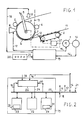
- Figure 1 shows in block diagram, a printer including the apparatus of the invention.
- the mechanical elements of the printer are shown in side view.
- the printer comprises a tractor pair 2, one of the tractors being shown in the figure, a revolving platen 3, a printing member 8, a motor 1 for actuating the tractors and the platen, a control unit 19 and a control keyboard 20.
- the tractors 2 push a continuous form 11 towards the platen 3 and a guiding element 6 drives the module along the periphery of the platen 3.
- the continuous form interposes between the platen 3 and the printing member 8.
- Pressure rollers 5 press the continuous form against the platen.
- the continuous form is pulled towards the printing line defined by the printing member 8, owing to the friction between module and revolving platen, with the drawbacks already mentioned in case a multiple copy continuous form is used.
- Numeral 12 references an exemplary wave formed by the rear copy of the form, between tractors 2 and platen 3.
- Form 11 downstream the pressure rollers 5, leaves the platen and rests on a laying down plane and a collection basket not shown.
- a printer like the one shown may also use single sheets as a printing medium, in alternative to the continuous form.
- a single sheet, referenced by numeral 13 is inserted between platen 3 and some pressure rollers 4.
- a guiding element 7 holds the single sheet in proximity of the platen.
- the single sheet follows the same path of the continuous form: it is driven along the periphery of the platen by guiding element 6 untill it interposes between printing member 8 and platen 3.
- a mechanical clutch 27, manually operated or controlled by unit 19 enables to decouple tractors 2 from motor 1, so that the platen may be rotated independently of the tractors.
- the motor 1 is a step motor, it may be operated by unit 19 through leads 15, without need of feedback.
- an encoder 14 coupled to the motor provides unit 19, through leads 16, with feedback signals which enable to detect the rotor position and, in case, its speed.
- Control unit 19 controls, in known manner, the printing member 8, through leads 17.
- a lever 9, acting on the position of the platen shaft, enables to change the platen distance from the printing member 8 as a function of the printing support thickness (single sheet, multiple copy continuous form).
- the apparatus of the present invention essentially comprises some elements already present in the prior art printers, such as tractors 2, a motor 1 and a control unit 19.
- control unit 19 It requires two additional elements in the control unit 19.
- FIG. 1 shows in block diagram the essential constitutive elements of control unit 19.
- Unit 19 comprises a microprocessor 22, a read only control store 23 and a read/write memory 24.
- a communication bus 25 enables the microprocessor to receive signals from several printer elements, via leads 16,21,18 and to forward suitable control signals, via leads 15,17.
- the microprocessor is controlled by suitable control programs, stored in control store 23.
- Memory 24 is used as a "buffer” where to store and read information such as sequences of characters to be printed, line feed commands, and so on.
- control unit further comprises a counter 26 and contains, in control store 23, a suitable control routine.
- Counter 26 receives, through leads 15, the actuation commands forwarded to motor 1 and increments by one unit at each command sent to the motor which causes its rotor to move of a predetermined incremental amount, hence causing a predetermined feeding of the printing support.
- the signals for incrementing the counter may be obtained from encoder 14, through leads 16.
- the counter 26 When the counter 26 reaches a predetermined counting state, corresponding to a predetermined forward feeding of the printing support, it generates an interrupt signal which is received by processor 22 through lead 29.
- processor 22 fetches a control routine 28, specific of this invention, from store 23.
- This control routine causes the operation of motor 1 in the reverse direction, so as to draw a predetermined amount of the printing support from the platen towards the tractors, then the operation of motor 1 in normal or forward direction so as to cause a predetermined amount of the printing support, preferably equal to the amount drawn in reverse direction, to be fed forward and last the resetting of counter 26, through a lead 30.
- the experimentation shows that the slipping occurring between the copies of a continuous form, in the course of its forward feeding for an amount in the order of 1-2 meters, is integrally recovered with a reverse motion in order of a tenth of centimeters.
- control routine 28 may be fetched only when the printing support is a multiple copy continuous form.
- a switch 10 may be provided, operated by lever 9 when it is set in a position corresponding to a printing support of greater thickness (multiple copy module).
- Switch 10 forwards to control unit 19, through lead 18, an enabling signal for counter 26, which missing such signal does not increments or is held in reset status.
- enabling signal may be provided by keyboard 20 through lead 21 (Fig. 1).
- counter 26 may be replaced by a register or a memory location 31 in memory 24 where to store the counting information.
- the incrementing operation on the contents of the memory location 31 may be performed by processor 22.
- routine 28 which causes the execution of the method according to the invention may develop according to the following steps:
- control routine is very simple and may lead to several changes.
- steps 6) and 7) are performed may be inverted and the quantity M1 by which the module is fed back may differ from the quantity M2 by which the module is fed forward.
- M2 may be greater than M1 and logical step 7) may comprise step 1) of the routine.
- the module is first fed back for the amount M1, then advanced for the amount M2.
- the slipping recovery may be postponed untill printing of a full page has been completed, that is untill the control routine detects an end of page command or like signal.
Landscapes
- Handling Of Sheets (AREA)
Claims (4)
- Einrichtung zur Störungsverhütung in der Papierzufuhr eines EDV-Druckers, bei dem zwei Traktoren ein Durchschreib-Endlosformular einer Druckplatte zuführen, mit- einer Zählvorrichtung zum Erzeugen einer Anzeige, daß das Endlosformular um einen ersten vorgegebenen Betrag vorwärts bewegt wurde,- einer auf diese Anzeige ansprechenden Steuereinrichtung zum Steuern der Traktoren, um das Endlosformular um einen zweiten vorgegebenen Betrag rückwärts zu bewegen, der um wenigstens eine Größenordnung kleiner ist als der erstgenannte Betrag, und zum vorwärtsbewegen des Endlosformulars um einen dritten Betrag gleich oder von gleicher Größenordnung wie der zweite Betrag, wobei die Steuereinrichtung ferner die Zählvorrichtung in einen vorgegebenen Zustand zurücksetzt.
- Einrichtung nach Anspruch 1 mit einer Vorrichtung zum Signalisieren der Anwesenheit eines Durchschreib-Endlosformulars im Drucker und zum Aktivieren der Zählvorrichtung und/oder der Steuereinrichtung nur dann, wenn die Anwesenheit eines Durchschreib-Endlosformulars im Drucker signalisiert wird.
- Einrichtung nach Anspruch 1 mit einer Steuertaste zum Aktivieren der Zählvorrichtung und/oder der Steuereinrichtung auf Befehl dieser Taste.
- Verfahren zur Störungsverhütung in der Papierzufuhr eines EDV-Druckers, bei dem zwei Traktoren ein Durchschreib-Endlosformular einer Druckplatte zuführen, bestehend aus- Detektieren, ob das Endlosformular wenigstens um einen vorgegebenen ersten Betrag vorwärts bewegt wurde, und bei einer solchen Feststellung:- Rückwärtsbewegen des Endlosformulars um einen zweiten vorgegebenen Betrag, der wenigstens um eine Größenordnung kleiner ist als der erste Betrag, und- Vorwärtsbewegen des Endlosformulars um eine dritten vorgegebenen Betrag von der gleichen Größenordnung wie der zweite Betrag.
Applications Claiming Priority (2)
| Application Number | Priority Date | Filing Date | Title |
|---|---|---|---|
| IT2286788 | 1988-12-06 | ||
| IT8822867A IT1227501B (it) | 1988-12-06 | 1988-12-06 | Apparato e procedimento per prevenire l'inceppamento di dispositivi di alimentazione carta in stampanti di calcolatore |
Publications (2)
| Publication Number | Publication Date |
|---|---|
| EP0372318A1 EP0372318A1 (de) | 1990-06-13 |
| EP0372318B1 true EP0372318B1 (de) | 1993-02-03 |
Family
ID=11201355
Family Applications (1)
| Application Number | Title | Priority Date | Filing Date |
|---|---|---|---|
| EP89121741A Expired - Lifetime EP0372318B1 (de) | 1988-12-06 | 1989-11-24 | Verfahren und Vorrichtung für die Störungsverhütung in der Belegzufuhr von EDV-Druckern |
Country Status (3)
| Country | Link |
|---|---|
| EP (1) | EP0372318B1 (de) |
| DE (1) | DE68904746T2 (de) |
| IT (1) | IT1227501B (de) |
Families Citing this family (1)
| Publication number | Priority date | Publication date | Assignee | Title |
|---|---|---|---|---|
| JP3028107B2 (ja) * | 1991-04-11 | 2000-04-04 | ブラザー工業株式会社 | プリンタの連帳単票切換え装置 |
Family Cites Families (4)
| Publication number | Priority date | Publication date | Assignee | Title |
|---|---|---|---|---|
| US4898488A (en) * | 1986-08-22 | 1990-02-06 | Brother Kogyo Kabushiki Kaisha | Printer with multi-function paper feeding mechanism |
| US4925325A (en) * | 1987-04-23 | 1990-05-15 | Brother Kogyo Kabushiki Kaisha | Recording paper transporting device in a recording apparatus |
| JPH01103472A (ja) * | 1987-10-16 | 1989-04-20 | Brother Ind Ltd | 印字用シート頭出し機能付印字装置 |
| KR930009111B1 (ko) * | 1988-03-14 | 1993-09-23 | 세이꼬 엡슨 가부시끼가이샤 | 프린터의 급지장치 |
-
1988
- 1988-12-06 IT IT8822867A patent/IT1227501B/it active
-
1989
- 1989-11-24 DE DE8989121741T patent/DE68904746T2/de not_active Expired - Fee Related
- 1989-11-24 EP EP89121741A patent/EP0372318B1/de not_active Expired - Lifetime
Also Published As
| Publication number | Publication date |
|---|---|
| DE68904746T2 (de) | 1993-08-05 |
| IT8822867A0 (it) | 1988-12-06 |
| DE68904746D1 (de) | 1993-03-18 |
| EP0372318A1 (de) | 1990-06-13 |
| IT1227501B (it) | 1991-04-12 |
Similar Documents
| Publication | Publication Date | Title |
|---|---|---|
| JP2697276B2 (ja) | プリンタ | |
| JP3022228B2 (ja) | 用紙排出装置 | |
| US5129642A (en) | Controllable document drive and separation system | |
| CA1139986A (en) | In-feed paper buckel control apparatus | |
| EP1180488B1 (de) | Papierspender mit vereinfachtem Papierführungsaufbau, der mit einem Drucker verbindbar ist | |
| JP2943314B2 (ja) | プリンタ | |
| JPH0249911B2 (de) | ||
| EP0372318A1 (de) | Verfahren und Vorrichtung für die Störungsverhütung in der Belegzufuhr von EDV-Druckern | |
| US4775254A (en) | Lining method and apparatus for printers | |
| JPS62244674A (ja) | プリンタ | |
| US5588761A (en) | Document printer having skew detection | |
| US5417415A (en) | Method of straightening skew in cut sheet and apparatus therefor | |
| US5026183A (en) | Apparatus for feeding cut sheet paper and fan fold paper in a printer | |
| CN211195500U (zh) | 用于打印机的暂存式送纸器及打印机 | |
| JP2784329B2 (ja) | 用紙排出装置 | |
| JP2532178B2 (ja) | 印字用紙の位置決め機構 | |
| US4766446A (en) | Printing apparatus having means for providing tension to a recording material | |
| JP2587291Y2 (ja) | プリンタの転向部材変位機構 | |
| JP3087071B2 (ja) | プリンタの用紙ジャム防止装置 | |
| JP3371946B2 (ja) | 給紙装置 | |
| JP3786379B2 (ja) | 記録媒体の検出装置 | |
| JPH02147249A (ja) | 文書データ印刷方法と該印刷方法を実施する印刷装置及び該印刷装置を用いた文書編集印刷装置 | |
| JPH0416372A (ja) | 文書編集印刷装置 | |
| JP3196913B2 (ja) | プリンタの給紙制御装置 | |
| JP2876624B2 (ja) | 用紙搬送装置 |
Legal Events
| Date | Code | Title | Description |
|---|---|---|---|
| PUAI | Public reference made under article 153(3) epc to a published international application that has entered the european phase |
Free format text: ORIGINAL CODE: 0009012 |
|
| AK | Designated contracting states |
Kind code of ref document: A1 Designated state(s): DE FR GB NL |
|
| 17P | Request for examination filed |
Effective date: 19900619 |
|
| 17Q | First examination report despatched |
Effective date: 19920421 |
|
| GRAA | (expected) grant |
Free format text: ORIGINAL CODE: 0009210 |
|
| AK | Designated contracting states |
Kind code of ref document: B1 Designated state(s): DE FR GB NL |
|
| REF | Corresponds to: |
Ref document number: 68904746 Country of ref document: DE Date of ref document: 19930318 |
|
| ET | Fr: translation filed | ||
| PGFP | Annual fee paid to national office [announced via postgrant information from national office to epo] |
Ref country code: NL Payment date: 19931130 Year of fee payment: 5 |
|
| PLBE | No opposition filed within time limit |
Free format text: ORIGINAL CODE: 0009261 |
|
| STAA | Information on the status of an ep patent application or granted ep patent |
Free format text: STATUS: NO OPPOSITION FILED WITHIN TIME LIMIT |
|
| 26N | No opposition filed | ||
| PG25 | Lapsed in a contracting state [announced via postgrant information from national office to epo] |
Ref country code: NL Effective date: 19950601 |
|
| NLV4 | Nl: lapsed or anulled due to non-payment of the annual fee | ||
| REG | Reference to a national code |
Ref country code: GB Ref legal event code: IF02 |
|
| PGFP | Annual fee paid to national office [announced via postgrant information from national office to epo] |
Ref country code: FR Payment date: 20021108 Year of fee payment: 14 |
|
| PGFP | Annual fee paid to national office [announced via postgrant information from national office to epo] |
Ref country code: GB Payment date: 20021120 Year of fee payment: 14 |
|
| PGFP | Annual fee paid to national office [announced via postgrant information from national office to epo] |
Ref country code: DE Payment date: 20021128 Year of fee payment: 14 |
|
| PG25 | Lapsed in a contracting state [announced via postgrant information from national office to epo] |
Ref country code: GB Free format text: LAPSE BECAUSE OF NON-PAYMENT OF DUE FEES Effective date: 20031124 |
|
| PG25 | Lapsed in a contracting state [announced via postgrant information from national office to epo] |
Ref country code: DE Free format text: LAPSE BECAUSE OF NON-PAYMENT OF DUE FEES Effective date: 20040602 |
|
| GBPC | Gb: european patent ceased through non-payment of renewal fee |
Effective date: 20031124 |
|
| PG25 | Lapsed in a contracting state [announced via postgrant information from national office to epo] |
Ref country code: FR Free format text: LAPSE BECAUSE OF NON-PAYMENT OF DUE FEES Effective date: 20040730 |
|
| REG | Reference to a national code |
Ref country code: FR Ref legal event code: ST |