EP0372337A2 - Kraftfahrzeugsitz - Google Patents
Kraftfahrzeugsitz Download PDFInfo
- Publication number
- EP0372337A2 EP0372337A2 EP89121823A EP89121823A EP0372337A2 EP 0372337 A2 EP0372337 A2 EP 0372337A2 EP 89121823 A EP89121823 A EP 89121823A EP 89121823 A EP89121823 A EP 89121823A EP 0372337 A2 EP0372337 A2 EP 0372337A2
- Authority
- EP
- European Patent Office
- Prior art keywords
- backrest
- motor vehicle
- plastic
- seat
- vehicle seat
- Prior art date
- Legal status (The legal status is an assumption and is not a legal conclusion. Google has not performed a legal analysis and makes no representation as to the accuracy of the status listed.)
- Withdrawn
Links
Images
Classifications
-
- B—PERFORMING OPERATIONS; TRANSPORTING
- B60—VEHICLES IN GENERAL
- B60N—SEATS SPECIALLY ADAPTED FOR VEHICLES; VEHICLE PASSENGER ACCOMMODATION NOT OTHERWISE PROVIDED FOR
- B60N2/00—Seats specially adapted for vehicles; Arrangement or mounting of seats in vehicles
- B60N2/68—Seat frames
- B60N2/682—Joining means
Definitions
- the invention relates to a motor vehicle seat, consisting of the lower part of the seat and the backrest, with metal fittings provided with tabs connecting the lower part of the seat and the backrest and at least the backrest having a supporting structure made of plastic.
- Motor vehicle seats which have a metal frame, are designed so that the metal frame deforms when there is a certain overload in order to protect the user from major injuries in the event of a crash.
- Such a design of seat frames is not difficult, because metal structures have advantageous material-related properties and therefore react to loads beyond the elastic limit by the desired plastic deformation.
- the object is to improve motor vehicle seats in which at least their backrest has a plastic support structure in such a way that splintering of the plastic structure is avoided in the event of overloading, in particular in the event of a crash.
- the target deformation points can be designed in such a way that they respond when the seat, or in particular the backrest, is overloaded before the backrest breaks. In this way, breakage of the plastic structure with the dreaded splintering can be avoided.
- the target deformation point must of course be designed so that no plastic deformation occurs under normal load.
- the desired deformation point can expediently be designed in such a way that the force deformation behavior is characterized by a targeted increase in the force over a short distance. From a certain force absorption, the buckling or kinking of the tab at the desired deformation point keeps the force essentially constant at a certain level with constant increase in displacement.
- the target deformation point can be realized by beads or notches of a suitable size, reducing the cross-section of the tab and / or a suitable distance between the connection points.
- the material for the straps is steel, which has a favorable ratio of strength and plastic deformability, such as St 14 or USt 37-2.
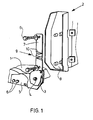
- the motor vehicle seat consists of a lower seat part 1 and a backrest 2, which are connected to one another via fittings 3 (only one visible).
- Both the lower seat part 1 and the backrest 2 are made of plastic, namely of polyamide 6 with 30% by weight glass fiber content, and are produced by injection molding.
- the fitting 3 has a joint 4 for adjusting the backrest 2 and is made of St 14 steel. It is with a flat sheet-metal tab 5 on the lower seat part 1 attached with screws 6.
- Another tab 7 is assigned to the support structure 8 of the backrest 2.
- the tab 7 is provided with a desired deformation point 9, which consists of two beads 10. These beads 10 extend across the tab 7 and run in opposite directions. If the backrest is pressurized in the rearward direction, the upper bead 10 is stretched and the lower one is compressed, energy being wasted.
Landscapes
- Engineering & Computer Science (AREA)
- Aviation & Aerospace Engineering (AREA)
- Transportation (AREA)
- Mechanical Engineering (AREA)
- Seats For Vehicles (AREA)
- Chair Legs, Seat Parts, And Backrests (AREA)
Abstract
Description
- Die Erfindung betrifft einen Kraftfahrzeugsitz, bestehend aus Sitzunterteil und Rückenlehne, wobei mit Laschen versehene Beschläge aus Metall Sitzunterteil und Rückenlehne verbinden und mindestens die Rückenlehne eine Tragstruktur aus Kunststoff aufweist.
- Kraftfahrzeugsitze, welche ein Metallgestell aufweisen, sind so ausgelegt, daß sich das Metallgestell bei einer bestimmten Überlastung verformt, um den Benutzer bei Crashunfällen vor größeren Verletzungen zu schützen. Eine solche Ausgestaltung von Sitzgestellen ist nicht schwierig, weil Metallkonstruktionen vorteilhafte materialbedingte Eigenschaften aufweisen und deshalb bei Belastungen über die Elastizitätsgrenze hinaus durch gewünschte plastische Verformung reagieren.
- Inzwischen finden aber auch Sitzgestelle aus thermoplastischen oder duroplastischen Kunststoffen Verwendung. Der Nachteil solcher Kunststoffkonstruktionen ist da durch bedingt, daß die in Frage kommenden, vorzugsweise glasfaserverstärkten Kunststoffe, wie Polyamid-6, Polyamid-6.6 oder Polycarbonat/ABS-Blend, einerseits einen hohen E-Modul aufweisen müssen, um eine ausreichende Steifigkeit zu erzielen, aber andererseits gerade solche Kunststoffe nur eine geringe Reißdehnung besitzen. Die Gesamtenergieaufnahme solcher Strukturen ist relativ niedrig.
- Es besteht die Aufgabe, Kraftfahrzeugsitze, bei denen zumindest deren Rückenlehne eine Tragstruktur aus Kunststoff aufweist, dahingehend zu verbessern, daß bei Überlastung, insbesondere bei Crashunfällen, ein Splittern der Kunststoffstruktur vermieden wird.
- Gelöst wird diese Aufgabe dadurch, daß die der Rückenlehne und/oder dem Unterteil zugeordneten Laschen der Beschläge mit mindestens einer Soll-Verformungsstelle versehen sind.
- Dadurch wird erreicht, daß man die Soll-Verformungsstellen derart ausbilden kann, daß sie bei Überlastung des Sitzes, bzw. insbesondere der Rückenlehne, ansprechen, bevor die Rückenlehne bricht. Auf diese Weise läßt sich ein Bruch der Kunststoffstruktur mit dem gefürchteten Splittern vermeiden. Andererseits muß die Soll-Verformungsstelle natürlich so ausgelegt sein, daß bei normaler Belastung keine plastische Verformung auftritt.
- Die Soll-Verformungsstelle läßt sich zweckmäßigerweise so ausbilden, daß das Kraftverformungsverhalten durch einen gezielten Anstieg der Kraft bei geringem Weg gekennzeichnet ist. Ab einer bestimmten Kraftaufnahme wird durch das Beulen oder Knicken der Lasche an der Soll-Verformungsstelle die Kraft unter ständiger Wegzunahme auf einem bestimmten Niveau im wesentlichen konstant gehalten.
- Die Soll-Verformungsstelle läßt sich durch Sicken oder Kerben geeigneter Größe, Verringerung des Laschenquerschnittes und/oder geeigneten Abstand der Anbindungspunkte realisieren. Als Material für die Laschen sieht man einen Stahl vor, welcher ein günstiges Verhältnis von Festigkeit und plastischer Verformbarkeit aufweist, wie beispielsweise St 14 oder USt 37-2.
- In der Zeichnung ist der neue Kraftfahrzeugsitz in einem Ausführungsbeispiel rein schematisch in Explosionsdarstellung wiedergegeben und nachstehend näher erläutert:
- Der Kraftfahrzeugsitz besteht aus einem Sitzunterteil 1 und einer Rückenlehne 2, welche über Beschläge 3 (nur einer sichtbar) miteinander verbunden sind. Sowohl das Sitzunterteil 1 als auch die Rückenlehne 2 bestehen aus Kunststoff, und zwar aus Polyamid-6 mit 30 Gew.-% Glasfasergehalt, und sind im Spritzgießverfahren hergestellt. Der Beschlag 3 weist ein Gelenk 4 zum Verstellen der Rückenlehne 2 auf und besteht aus Stahl St 14. Er ist mit einer flachen blechartigen Lasche 5 am Sitzunterteil 1 mittels Schrauben 6 befestigt. Eine weitere Lasche 7 ist der Tragstruktur 8 der Rückenlehne 2 zugeordnet. Auch hier erfolgt die Verbindung mit Schrauben 6. Die Lasche 7 ist mit einer Soll-Verformungsstelle 9 versehen, welche aus zwei Sicken 10 besteht. Diese Sicken 10 erstrecken sich quer über die Lasche 7 und laufen gegensinnig aus. Wird die Rückenlehne in Richtung nach hinten druckbelastet, wird die obere Sicke 10 gedehnt und die untere gestaucht, wobei Energie vernichtet wird.
Claims (1)
- Kraftfahrzeugsitz, bestehend aus einem Sitzunterteil (1) und Rückenlehne (2), wobei mit Laschen (5, 7) versehene Beschläge (3) aus Metall Sitzunterteil (1) und Rückenlehne (2) verbinden und mindestens die Rückenlehne (2) eine Tragstruktur (8) aus Kunststoff aufweist, dadurch gekennzeichnet, daß die der Rückenlehne (2) und/oder dem Sitzunterteil (1) zugeordneten Laschen (5, 7) der Beschläge (3) mit mindestens einer Soll-Verformungsstelle (9) versehen sind.
Applications Claiming Priority (2)
| Application Number | Priority Date | Filing Date | Title |
|---|---|---|---|
| DE3841535 | 1988-12-09 | ||
| DE19883841535 DE3841535A1 (de) | 1988-12-09 | 1988-12-09 | Kraftfahrzeugsitz |
Publications (2)
| Publication Number | Publication Date |
|---|---|
| EP0372337A2 true EP0372337A2 (de) | 1990-06-13 |
| EP0372337A3 EP0372337A3 (de) | 1991-08-28 |
Family
ID=6368820
Family Applications (1)
| Application Number | Title | Priority Date | Filing Date |
|---|---|---|---|
| EP19890121823 Withdrawn EP0372337A3 (de) | 1988-12-09 | 1989-11-25 | Kraftfahrzeugsitz |
Country Status (3)
| Country | Link |
|---|---|
| EP (1) | EP0372337A3 (de) |
| JP (1) | JPH02256533A (de) |
| DE (1) | DE3841535A1 (de) |
Cited By (7)
| Publication number | Priority date | Publication date | Assignee | Title |
|---|---|---|---|---|
| EP0463436A3 (en) * | 1990-06-23 | 1992-03-25 | Bayer Ag | Vehicle seat |
| FR2735730A1 (fr) * | 1995-06-21 | 1996-12-27 | Irausa Ing Sa | Dispositif de liaison articulee entre le dossier et l'assise d'un siege de vehicule |
| US5690386A (en) * | 1995-06-21 | 1997-11-25 | Irausa Ingeniera S.A. | Device for articulated connection between the backrest and the seat part of a vehicle seat |
| US6471292B1 (en) | 1998-03-17 | 2002-10-29 | Accra Teknik Ab | Frame for a vehicle seat |
| FR2832959A1 (fr) * | 2001-12-04 | 2003-06-06 | Faurecia Sieges Automobile | Structure d'element de siege pour vehicule et procede de fabrication d'une telle structure |
| WO2012084144A1 (de) * | 2010-12-21 | 2012-06-28 | Sitech Sitztechnik Gmbh | Fahrzeugsitzstruktur mit laserverfestigten bereichen |
| US10259358B2 (en) * | 2017-05-26 | 2019-04-16 | Toyota Boshoku Kabushiki Kaisha | Back frame attachment structure and vehicle seat |
Families Citing this family (3)
| Publication number | Priority date | Publication date | Assignee | Title |
|---|---|---|---|---|
| DE102007050091A1 (de) * | 2007-10-19 | 2009-04-23 | GM Global Technology Operations, Inc., Detroit | Fahrzeugsitz mit einem drehbaren Rückenteil |
| JP5986370B2 (ja) * | 2011-05-25 | 2016-09-06 | テイ・エス テック株式会社 | 車両用シート |
| JP6284206B2 (ja) * | 2016-10-21 | 2018-02-28 | テイ・エス テック株式会社 | 車両用シート |
Family Cites Families (3)
| Publication number | Priority date | Publication date | Assignee | Title |
|---|---|---|---|---|
| US4688662A (en) * | 1985-05-16 | 1987-08-25 | The Lamson & Sessions Co. | Energy absorber |
| DE3706394C1 (en) * | 1987-02-27 | 1988-05-11 | Audi Ag | Backrest for vehicle front seats |
| DE3714588C2 (de) * | 1987-05-01 | 1998-05-14 | Bayer Ag | Sicherheits-Lehnenholm aus Kunststoff |
-
1988
- 1988-12-09 DE DE19883841535 patent/DE3841535A1/de active Granted
-
1989
- 1989-11-25 EP EP19890121823 patent/EP0372337A3/de not_active Withdrawn
- 1989-12-05 JP JP31445589A patent/JPH02256533A/ja active Pending
Cited By (11)
| Publication number | Priority date | Publication date | Assignee | Title |
|---|---|---|---|---|
| EP0463436A3 (en) * | 1990-06-23 | 1992-03-25 | Bayer Ag | Vehicle seat |
| FR2735730A1 (fr) * | 1995-06-21 | 1996-12-27 | Irausa Ing Sa | Dispositif de liaison articulee entre le dossier et l'assise d'un siege de vehicule |
| EP0749868A1 (de) * | 1995-06-21 | 1996-12-27 | Irausa Ingenieria, S.A. | Gelenkverbindung zwischen der Rückenlehne und dem Sitzteil eines Fahrzeugsitzes |
| US5690386A (en) * | 1995-06-21 | 1997-11-25 | Irausa Ingeniera S.A. | Device for articulated connection between the backrest and the seat part of a vehicle seat |
| US6471292B1 (en) | 1998-03-17 | 2002-10-29 | Accra Teknik Ab | Frame for a vehicle seat |
| FR2832959A1 (fr) * | 2001-12-04 | 2003-06-06 | Faurecia Sieges Automobile | Structure d'element de siege pour vehicule et procede de fabrication d'une telle structure |
| US6767067B2 (en) | 2001-12-04 | 2004-07-27 | Faurecia Sieges D'automobile S.A. | Structure for a vehicle seat element, and a method of making such a structure |
| WO2012084144A1 (de) * | 2010-12-21 | 2012-06-28 | Sitech Sitztechnik Gmbh | Fahrzeugsitzstruktur mit laserverfestigten bereichen |
| CN103338973A (zh) * | 2010-12-21 | 2013-10-02 | 西德科汽车座椅技术有限责任公司 | 具有激光加固区域的车辆座椅结构 |
| CN103338973B (zh) * | 2010-12-21 | 2016-02-24 | 西德科汽车座椅技术有限责任公司 | 具有激光加固区域的车辆座椅结构 |
| US10259358B2 (en) * | 2017-05-26 | 2019-04-16 | Toyota Boshoku Kabushiki Kaisha | Back frame attachment structure and vehicle seat |
Also Published As
| Publication number | Publication date |
|---|---|
| JPH02256533A (ja) | 1990-10-17 |
| EP0372337A3 (de) | 1991-08-28 |
| DE3841535C2 (de) | 1991-04-25 |
| DE3841535A1 (de) | 1990-06-13 |
Similar Documents
| Publication | Publication Date | Title |
|---|---|---|
| DE4020057C2 (de) | Fahrzeugsitz | |
| DE2546157A1 (de) | Fahrzeug-sitzlehne | |
| DE3841535C2 (de) | ||
| DE102007017991B4 (de) | Blattfeder aus einem Faser-Kunststoff-Verbundwerkstoff und Krafteinleitungselement für dieselbe | |
| DE20007526U1 (de) | Stabilisiervorrichtung für eine in einem Kraftfahrzeug lageveränderlich angeordnete Armaturentafel | |
| WO2010069087A1 (de) | Biegeträger | |
| DE4115812C2 (de) | Befestigungsvorrichtung für ein Abschleppmittel an einem Kraftfahrzeug | |
| DE3021676C2 (de) | Elastisches Abstützelement, insbesondere für die Antriebsmaschine in einem Kraftfahrzeug | |
| DE3007897A1 (de) | Lastbuegel fuer fahrzeuge, insbesondere kraftfahrzeuge | |
| EP0897344B1 (de) | Sitz, insbesondere fahrzeugsitz | |
| EP1613515A1 (de) | Umlenkvorrichtung für einen sicherheitsgurt | |
| DE102007002209A1 (de) | Unterbodenverkleidung für ein Kraftfahrzeug | |
| DE69925889T2 (de) | Türverstärkungsvorrichtung für Kraftfahrzeug | |
| AT395306B (de) | Rammschutztraeger fuer eine tuer und eine seitenwand einer kraftfahrzeugkarosserie | |
| DE102005060609B3 (de) | Rahmenvorderteil für einen Lastkraftwagen | |
| DE102005044286A1 (de) | Kraftfahrzeug mit einem Spritzwasserbehälter | |
| EP4282712A1 (de) | Freizeitfahrzeug, insbesondere wohnmobil, und gurtbockanordnung | |
| DE10032734A1 (de) | Fußstütze für den Boden eines Kraftfahrzeuges | |
| EP0449228B1 (de) | Elastisches Motorlager in Form eines Keillagers | |
| AT519986B1 (de) | Trittplatteneinheit für fahrzeuge | |
| DE1782915C3 (de) | Rückentragbares Pflanzenschutz- | |
| EP0736417A1 (de) | Tragelement für Kraftfahrzeug-Dachlastenträger | |
| DE29503151U1 (de) | Schwingungstilger | |
| DE1655624A1 (de) | Polsterteil,wie Armlehne,Griff od.dgl.,fuer die Innenausstattung von Kraftfahrzeugen | |
| DE20003052U1 (de) | Schalenförmiges Bauteil aus Kunststoff mit Soll-Knickstelle |
Legal Events
| Date | Code | Title | Description |
|---|---|---|---|
| PUAI | Public reference made under article 153(3) epc to a published international application that has entered the european phase |
Free format text: ORIGINAL CODE: 0009012 |
|
| 17P | Request for examination filed |
Effective date: 19891125 |
|
| AK | Designated contracting states |
Kind code of ref document: A2 Designated state(s): DE ES FR GB IT |
|
| PUAL | Search report despatched |
Free format text: ORIGINAL CODE: 0009013 |
|
| AK | Designated contracting states |
Kind code of ref document: A3 Designated state(s): DE ES FR GB IT |
|
| 17Q | First examination report despatched |
Effective date: 19921214 |
|
| STAA | Information on the status of an ep patent application or granted ep patent |
Free format text: STATUS: THE APPLICATION HAS BEEN WITHDRAWN |
|
| 18W | Application withdrawn |
Withdrawal date: 19930416 |