EP0372339A2 - Rückenlehnen-Tragstruktur für einen Fahrzeugsitz und Fahrzeugsitz-Rückenlehne mit dieser Rückenlehnen-Tragstruktur - Google Patents
Rückenlehnen-Tragstruktur für einen Fahrzeugsitz und Fahrzeugsitz-Rückenlehne mit dieser Rückenlehnen-Tragstruktur Download PDFInfo
- Publication number
- EP0372339A2 EP0372339A2 EP89121825A EP89121825A EP0372339A2 EP 0372339 A2 EP0372339 A2 EP 0372339A2 EP 89121825 A EP89121825 A EP 89121825A EP 89121825 A EP89121825 A EP 89121825A EP 0372339 A2 EP0372339 A2 EP 0372339A2
- Authority
- EP
- European Patent Office
- Prior art keywords
- support structure
- backrest support
- backrest
- structure according
- vehicle seat
- Prior art date
- Legal status (The legal status is an assumption and is not a legal conclusion. Google has not performed a legal analysis and makes no representation as to the accuracy of the status listed.)
- Granted
Links
Images

Classifications
-
- B—PERFORMING OPERATIONS; TRANSPORTING
- B60—VEHICLES IN GENERAL
- B60N—SEATS SPECIALLY ADAPTED FOR VEHICLES; VEHICLE PASSENGER ACCOMMODATION NOT OTHERWISE PROVIDED FOR
- B60N2/00—Seats specially adapted for vehicles; Arrangement or mounting of seats in vehicles
-
- B—PERFORMING OPERATIONS; TRANSPORTING
- B60—VEHICLES IN GENERAL
- B60R—VEHICLES, VEHICLE FITTINGS, OR VEHICLE PARTS, NOT OTHERWISE PROVIDED FOR
- B60R7/00—Stowing or holding appliances inside vehicle primarily intended for personal property smaller than suit-cases, e.g. travelling articles, or maps
- B60R7/04—Stowing or holding appliances inside vehicle primarily intended for personal property smaller than suit-cases, e.g. travelling articles, or maps in driver or passenger space, e.g. using racks
- B60R7/043—Stowing or holding appliances inside vehicle primarily intended for personal property smaller than suit-cases, e.g. travelling articles, or maps in driver or passenger space, e.g. using racks mounted on or under a seat
-
- B—PERFORMING OPERATIONS; TRANSPORTING
- B60—VEHICLES IN GENERAL
- B60N—SEATS SPECIALLY ADAPTED FOR VEHICLES; VEHICLE PASSENGER ACCOMMODATION NOT OTHERWISE PROVIDED FOR
- B60N2/00—Seats specially adapted for vehicles; Arrangement or mounting of seats in vehicles
- B60N2/68—Seat frames
- B60N2/686—Panel like structures
-
- B—PERFORMING OPERATIONS; TRANSPORTING
- B60—VEHICLES IN GENERAL
- B60N—SEATS SPECIALLY ADAPTED FOR VEHICLES; VEHICLE PASSENGER ACCOMMODATION NOT OTHERWISE PROVIDED FOR
- B60N2/00—Seats specially adapted for vehicles; Arrangement or mounting of seats in vehicles
- B60N2/80—Head-rests
- B60N2/806—Head-rests movable or adjustable
-
- Y—GENERAL TAGGING OF NEW TECHNOLOGICAL DEVELOPMENTS; GENERAL TAGGING OF CROSS-SECTIONAL TECHNOLOGIES SPANNING OVER SEVERAL SECTIONS OF THE IPC; TECHNICAL SUBJECTS COVERED BY FORMER USPC CROSS-REFERENCE ART COLLECTIONS [XRACs] AND DIGESTS
- Y10—TECHNICAL SUBJECTS COVERED BY FORMER USPC
- Y10S—TECHNICAL SUBJECTS COVERED BY FORMER USPC CROSS-REFERENCE ART COLLECTIONS [XRACs] AND DIGESTS
- Y10S297/00—Chairs and seats
- Y10S297/02—Molded
Definitions
- the invention relates to a backrest support structure for a vehicle seat, in particular a motor vehicle seat, and a vehicle seat backrest with this backrest support structure.
- Backrest support structures for vehicle seats in particular motor vehicle seats, generally consist of tubular steel or sheet metal structures.
- complex stamped and bent parts have to be manufactured in complex processes, assembled and protected against rust. They require additional coverage, because otherwise they are not accepted as visible structures by the buyer.
- the support structure and back cushion as well as the cover are connected to one another in such a way that a defective cushion or cover can only be replaced with difficulty or not at all.
- the task is to provide a backrest support structure for vehicle seats, in particular motor vehicle seats, but also for aircraft or boat seats, which is easy to manufacture and has the necessary strength properties.
- a back shell which is surrounded by a cassette-like frame, which consists of U-profile-like side spars that are open to the outside and a U-profile-like cross bar that connects the upper ends of the side spars, the back shell and spars being made of consist of a single injection molded part.
- This design of the backrest support structure allows inexpensive series production from suitable thermoplastic or thermosetting plastics, in particular from polyamide-6, polyamide-6.6 or a polycarbonate / acrylonitrile-butadiene-styrene-caopolymer blend, each with a glass fiber content of approximately 20 to 40% by weight .%.
- This backrest support structure must of course withstand normal loads.
- the connection points for the hinge fittings must also have appropriate strength.
- predetermined deformation points are provided on other parts of the seat, for example on the fittings, which yield more than the backrest support structure.
- the design of the spars as U-profiles comes very close to closed hollow profiles in terms of bending and torsional rigidity. The latter can only be removed from the mold in a very complex manner.
- the back shell can be flat, but it can also approximate the body shape.
- the U-profile side rails and the cross rail form a rigid frame for the seat cushion, which rests against the back shell.
- the connecting lugs of the fittings as well as the seat adjustment and possibly other elements can be accommodated in the open cavities of the side rails.
- the width of the side rails can vary over their length.
- the back shell preferably merges towards the side bars toward the front with a rounding into an angle, which, branching out, ends in the middle webs of the side bars and into their front legs via a back swing.
- This plastic-compatible design prevents notch cracks and ensures good force transmission between the bars and the back shell.
- At least one of the spars has a cover.
- This cover is used for the optics. It can be detachable and interchangeable; but it can also be inextricably linked to the side rail to form a box section in order to increase the strength. The same applies to the cover of the cross bar.
- Molded-on ribs are preferably arranged in the cavities of the spars.
- Another special embodiment is characterized in that the front legs of the side rails are curved forward like a shell.
- This design gives the back cushion to be placed on the side a reinforcement, whereby the occupant's body is better guided laterally. In this way, they form a kind of tub together with the backrest.
- cross member is open to the front and a headrest holding plate forms the cover.
- This so-called headrest support plate has catches for the adjustability of the headrest.
- the cross member is open to the rear and forms a storage chamber, which is assigned a flap as a cover.
- this storage chamber it can be used for cards, first-aid kits, etc.
- This flap should be designed to be safe from injury and in particular should have a recessed handle.
- the flap is preferably provided on the outside with a protective cushion.
- the new backrest support structure also has the advantage that the back cushion is easily replaceable. Likewise, it is no longer necessary to arrange the cover directly on the back cushion, but it can be pulled over the backrest or attached to it with an appropriate design. A releasable attachment of the cover is also possible if the cushion can be attached to the backrest support structure with the cover. In this way it is possible to shift the equipment of the vehicle with a back cushion of suitable hardness and a seat cover that is convenient for the buyer to the sales agencies, so that assembly line production becomes more efficient. For this, the wishes of the buyer in said direction can also be met at the last moment, i.e. before handing over the vehicle.
- the novel vehicle seat backrest with a backrest support structure of the type described above is characterized in that the back cushion laterally surrounded by the frame at least partially covers the front legs of the side rails.
- the back cushion preferably also covers the front side of the crossbar.
- this part of the backrest support structure also has a padding for occupants of greatly different sizes in order to avoid injuries in the event of a crash.
- the back cushion covers the outer side of the side rails.
- This embodiment not only serves for the optics, but also reduces the risk of injury.
- the backrest support structure 1 consists of an injection molded part made of polyamide 6 with 35 wt .-%. Glass fiber content.
- a frame 2 made of side members 3, 4 and a cross member 5 surrounds a back shell 6.
- the side members 3, 4 have a U-shaped cross section and each have a front leg 7, a central web 8 and a rear leg 9. Molded-on ribs 11 are arranged in the cavity 10 thus formed.
- reinforcements 12 are provided for the connection of the fittings and the inclination adjustment of the backrest.
- the cross member 5 which is closed on the back and in this way has a U-shaped cross section with a wide central web 13, an upper leg 14 and a lower leg 15, connects the upper ends of the side members 3, 4.
- This cavity 16 is closed by a cover 18 shown in the outline, which is equipped as a so-called headrest holding plate with a not shown, pointing into the cavity 16 for the headrest.
- This headrest support plate 18 is shaped such that it lies precisely between the legs 14, 15 and thus contributes to the stiffening.
- the backrest support structure 21 consists of an injection molded part made of polycarbonate / acrylonitrile-butadiene-styrene copolymer with a glass fiber content of 30% by weight.
- a frame 22 made of side members 23, 24 and a cross member 25 surrounds a back shell 26.
- the side members 23, 24 have a U-shaped cross section and each have a front leg 27, a central web 28 and a rear leg 29. Molded-on ribs 31 are arranged in the cavity 30 formed. In the lower region of the cavities 30, reinforcements 32 are provided for the connection of the fittings and the inclination adjustment of the backrest.
- the cross member 25 is closed at the front and in this way forms a U-shaped cross section with a wide central web 33, an upper leg 34 and a lower leg 35.
- the cavity 36 thus formed serves as a storage chamber and is provided with a cover 37 designed as a flap .
- This flap 37 is equipped on the outside with a protective pad 38 to protect the rear passengers in the event of a crash.
- FIG. 3 shows a cover 39 for the left side rail 23 according to FIG. 2, which snaps into the side rail 23 with snap connections (not shown).
- This bend 43 branches off and goes on the one hand via a backswing 46 into the central web 44 and on the other hand kinks at an angle ⁇ 2 of 15 ° to end in the front leg 47.
- the rear leg is labeled 48.
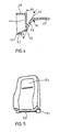
- a back cushion 52 and a cover 53 are already arranged on the backrest support structure 51.
Landscapes
- Engineering & Computer Science (AREA)
- Mechanical Engineering (AREA)
- Aviation & Aerospace Engineering (AREA)
- Transportation (AREA)
- Seats For Vehicles (AREA)
- Chair Legs, Seat Parts, And Backrests (AREA)
Abstract
Description
- Die Erfindung betrifft eine Rückenlehnen-Tragstruktur für einen Fahrzeugsitz, insbesondere Kraftfahrzeugsitz, sowie eine Fahrzeugsitz-Rückenlehne mit dieser Rückenlehnen-Tragstruktur.
- Rückenlehnen-Tragstrukturen für Fahrzeugsitze, insbesondere Kfz-Sitze, bestehen in der Regel aus Stahlrohr- oder Blechkonstruktionen. Hierzu müssen komplexe Stanz- und Biegeteile in aufwendigen Verfahren gefertigt, zusammengefügt und gegen Rosten geschützt werden. Sie bedürfen einer zusätzlichen Abdeckung, weil sie als sichtbare Strukturen ansonsten vom Käufer nicht akzeptiert werden. Häufig sind Tragstruktur und Rückenpolster sowie auch der Bezug derart miteinander verbunden, daß ein Austausch eines schadhaften Polsters oder Bezuges allein nur schwer oder gar nicht möglich ist.
- Es besteht die Aufgabe, eine Rückenlehnen-Tragstruktur für Fahrzeugsitze, insbesondere Kfz-Sitze, aber auch für Flugzeug- oder Bootsitze zu finden, welche leicht herstellbar ist und die notwendigen Festigkeitseigenschaften aufweist.
- Gelöst wird diese Aufgabe durch eine Rückenschale, welche kassettenartig von einem Rahmen umgeben ist, welcher aus U-profilartigen, nach außen hin offenen Seitenholmen und einem die oberen Enden der Seitenholme verbindenden, einseitig offenen, U-profilartigen Querholm besteht, wobei Rückenschale und Holme aus einem einzigen Spritzgußteil bestehen.
- Diese Gestaltung der Rückenlehnen-Tragstruktur erlaubt eine preiswerte Serienfertigung aus geeigneten thermoplastischen oder duroplastischen Kunststoffen, insbesondere aus Polyamid-6, Polyamid-6.6 oder einem Polycarbonat/Acrylnitril-Butadien-Styrol-Caopolymer-Blend, jeweils mit einem Glasfasergehalt von etwa 20 bis 40 Gew.%. Diese Rückenlehnen-Tragstruktur muß selbstverständlich normalen Beanspruchungen standhalten. Auch die Anbindungspunkte für die Gelenkbeschläge müssen entsprechende Festigkeit aufweisen. Um ein Brechen und Splittern der Rückenlehnen-Tragstruktur bei Crashunfällen zu vermeiden, sieht man an anderen Teilen des Sitzes, beispielsweise an den Beschlägen, Sollverformungsstellen vor, welche eher nachgeben als die Rückenlehnen-Tragstruktur. Die Ausbildung der Holme als U-Profile kommt bezüglich der Biege- und Torsionssteigigkeit geschlossenen Hohlprofilen recht nahe. Letztere lassen sich aber nur sehr aufwendig entformen. Für die Fertigung der neuartigen Rückenlehnen-Tragstruktur sind im Formwerkzeug lediglich zwei Seitenschieber erforderlich. Die Rückenschale kann flach sein, sie kann aber auch der Körperform angenähert sein. Die U-profilartigen Seitenholme sowie der Querholm bilden einen steifen Rahmen für die Aufnahme des Sitzpolsters, welches gegen die Rückenschale anliegt. In den offenen Hohlräumen der Seitenholme lassen sich die Anschlußlaschen der Beschläge sowie die Sitzverstellung und gegebenenfalls noch andere Elemente unterbringen. Die Breite der Seitenholme kann über ihre Länge variieren.
- Vorzugsweise geht die Rückenschale zu den Seitenholmen hin nach vorn mit einer Abrundung in eine Abwinkelung über, welche, sich verzweigend, über einen Rückschwung in die Mittelstege der Seitenholme und in deren vordere Schenkel ausläuft.
- Durch diese kunststoffgerechte Gestaltung werden Kerbrisse vermieden und gute Krafteinleitungen zwischen den Holmen und der Rückenschale gewährleistet.
- Gemäß einer besonderen Ausführungsform weist mindestens einer der Holme eine Abdeckung auf.
- Diese Abdeckung dient der Optik. Sie kann lösbar und austauschbar sein; sie kann aber auch mit dem Seitenholm zu einem Kastenprofil unlösbar verbunden sein, um die Festigkeit zu erhöhen. Gleiches gilt für die Abdeckung des Querholmes.
- Vorzugsweise sind in den Hohlräumen der Holme angeformte Rippen angeordnet.
- Diese dienen der Verstärkung und erhöhen insbesondere die Biege- und Torsionssteifigkeit. Sie lassen sich bei entsprechender Gestaltung des Formhohlraumes des Formwerkzeuges unmittelbar mit anspritzen, so daß keine zusätzlichen Arbeiten entstehen.
- Eine weitere besondere Ausführungsform ist dadurch gekennzeichnet, daß die vorderen Schenkel der Seitenholme schalenartig nach vorne gewölbt sind.
- Diese Gestaltung gibt dem aufzulegenden Rückenpolster eine seitliche Verstärkung, wodurch der Körper des Insassen seitlich besser geführt ist. Auf diese Weise bilden sie zusammen mit der Rückenlehne eine Art Wanne.
- Eine weitere besondere Ausführungsform zeigt, daß der Querholm nach vorne offen ist und eine Kopfstützenhalteplatte die Abdeckung bildet.
- Diese sogenannte Kopfstützenhalteplatte trägt Rasten für die Verstellbarkeit der Kopfstütze.
- Gemäß einer anderen Ausführungsform ist der Querholm nach hinten offen und bildet eine Ablagekammer, welcher als Abdeckung eine Klappe zugeordnet ist.
- Je nach Größe dieser Ablagekammer läßt sie sich für Karten, Verbandskasten usw. verwenden. Diese Klappe sollte verletzungssicher gestaltet sein und insbesondere einen versenkten Griff aufweisen.
- Vorzugsweise ist die Klappe außenseitig mit einem Schutzpolster versehen.
- Dies dient dem Schutz der Fondinsassen bei Crashunfällen.
- Die neuartige Rückenlehnen-Tragstruktur bringt außerdem den Vorteil, daß das Rückenpolster ohne Schwierigkeiten austauschbar ist. Ebenso ist es nicht mehr erforderlich, den Bezug unmittelbar auf dem Rückenpolster anzuordnen, sondern er läßt sich bei entsprechender Gestaltung über die Rückenlehne ziehen oder an ihr befestigen. Eine lösbare Befestigung des Bezuges ist ebenfalls möglich, wenn man das Polster mit dem Bezug an der Rückenlehnen-Tragstruktur befestigen kann. Auf diese Weise ist es möglich, die Ausstattung des Fahrzeuges mit einem Rückenpolster geeigneter Härte und einem dem Käufer genehmen Sitzbezug in die Verkaufsagenturen zu verlagern, so daß die Fließbandproduktion rationeller wird. Dafür kann den Wünschen des Käufers in besagter Richtung auch noch im letzten Moment, d.h. vor der Fahrzeugübergabe, nachgekommen werden.
- Die neuartige Fahrzeugsitz-Rückenlehne mit einer Rückenlehnen-Tragstruktur der vorbeschriebenen Art ist dadurch gekennzeichnet, daß das vom Rahmen seitlich umgebene Rückenpolster mindestens teilweise die vorderen Schenkel der Seitenholme überdeckt.
- Dadurch wird erreicht, daß gerade in diesem Bereich gegenüber dem Mittelteil härter wirkende Seitenführungszonen erzielt werden, ohne daß man Polster mit Zonen von Schaumstoff unterschiedlicher Härte benötigt.
- Vorzugsweise überdeckt das Rückenpolster auch die vordere Seite des Querholmes.
- Auf diese Weise wird dafür Sorge getragen, daß für Insassen stark abweichender Größe auch diese Partie der Rückenlehnen-Tragstruktur eine Polsterung aufweist, um bei Crashunfällen Verletzungen zu vermeiden.
- Gemäß einer weiteren besonderen Ausführungsform überdeckt das Rückenpolster die außenliegende Seite der Seitenholme.
- Diese Ausführungsform dient nicht nur der Optik, sondern vermindert auch die Verletzungsgefahr.
- In der Zeichnung ist die neue Fahrzeugsitz-Rückenlehne mit der neuartigen Rückenlehnen-Tragstruktur in einem Ausführungsbeispiel rein schematisch dargestellt und nachstehend näher erläutert. Es zeigen:
- Fig. 1 eine Rückenlehnen-Tragstruktur mit vorne offenem Querholm in räumlicher Darstellung mit seitlichem Blick von vorn,
- Fig. 2 eine Rückenlehnen-Tragstruktur mit hinten offenem Querholm in räumlicher Darstellung mit seitlichem Blick von hinten,
- Fig. 3 eine Abdeckung für einen Seitenholm in räumlicher Darstellung,
- Fig. 4 einen Abriß eines Querschnittes durch die Rückenlehnen-Tragstruktur und
- Fig. 5 eine Rückenlehne.
- In Fig. 1 besteht die Rückenlehnen-Tragstruktur 1 aus einem Spritzgußformteil aus Polyamid-6 mit 35 Gew.-%. Glasfasergehalt. Ein Rahmen 2 aus Seitenholmen 3, 4 sowie einem Querholm 5 umgibt eine Rückenschale 6. Die Seitenholme 3, 4 besitzen U-förmigen Querschnitt und weisen jeweils einen vorderen Schenkel 7, einen Mittelsteg 8 und einen hinteren Schenkel 9 auf. In dem so gebildeten Hohlraum 10 sind angeformte Rippen 11 angeordnet. Im unteren Bereich der Hohlräume 10 der Seitenholme 3, 4 sind Verstärkungen 12 für den Anschluß der Beschläge und die Neigungsverstellung der Rückenlehne vorgesehen. Der Querholm 5, welcher rückseitig geschlossen ist und auf diese Weise einen U-förmigen Querschnitt mit einem breiten Mittelsteg 13, einem oberen Schenkel 14 und einem unteren Schenkel 15 aufweist, verbindet die oberen Enden der Seitenholme 3, 4. In dem gebildeten Hohlraum 16 befinden sich auch noch angeformte Führungen 17 für eine Kopfstütze. Dieser Hohlraum 16 ist durch eine im Abriß dargestellte Abdeckung 18 verschlossen, welche als sogenannte Kopfstützenhalteplatte mit einer nicht dargestellten, in den Hohlraum 16 weisenden Raste für die Kopfstütze ausgestattet ist. Diese Kopfstützenhalteplatte 18 ist derart geformt, daß sie paßgenau zwischen den Schenkeln 14, 15 liegt und somit zur Versteifung beiträgt.
- In Fig. 2 besteht die Rückenlehnen-Tragstruktur 21 aus einem Spritzgußformteil aus Polycarbonat/Acrylnitril-Butadien-Styrol-Copolymer mit 30 Gew.-% Glasfasergehalt. Ein Rahmen 22 aus Seitenholmen 23, 24 sowie einem Querholm 25 umgibt eine Rückenschale 26. Die Seitenholme 23, 24 besitzen U-förmigen Querschnitt und weisen jeweils einen vorderen Schenkel 27, einen Mittelsteg 28 und einen hinteren Schenkel 29 auf. In dem gebildeten Hohlraum 30 sind angeformte Rippen 31 angeordnet. Im unteren Bereich der Hohlräume 30 sind Verstärkungen 32 für den Anschluß der Beschläge und die Neigungsverstellung der Rückenlehne vorgesehen. Der Querholm 25 ist vorderseitig geschlossen und bildet auf diese Weise einen U-förmigen Querschnitt mit einem breiten Mittelsteg 33, einem oberen Schenkel 34 und einem unteren Schenkel 35. Der so gebildete Hohlraum 36 dient als Ablagekammer und ist mit einer als Klappe gestalteten Abdeckung 37 versehen. Diese Klappe 37 ist außenseitig mit einem Schutzpolster 38 zum Schutz der Fondinsassen bei Crashunfällen ausgestattet.
- Fig. 3 zeigt eine Abdeckung 39 für den linken Seitenholm 23 gemäß Fig. 2, welche mit nicht dargestellten Schnappverbindungen in den Seitenholm 23 einrastet.
- In Fig. 4 geht die Rückenschale 41 über eine Abrundung 42 vom Radius R = 50 mm in eine Abwinkelung 43 über, welche mit dem Mittelsteg 44 des Seitenholmes 45 einen Winkel α₁ von 45° bildet. Diese Abwinkelung 43 verzweigt sich und geht einerseits über einen Rückschwung 46 in den Mittelsteg 44 über und knickt andererseits mit einem Winkel α₂ van 15° ab, um in den vorderen Schenkel 47 auszulaufen. Der hintere Schenkel ist mit 48 bezeichnet.
- In Fig. 5 sind auf der Rückenlehnen-Tragstruktur 51 bereits ein Rückenpolster 52 und ein Bezug 53 angeordnet.
Claims (11)
Applications Claiming Priority (2)
| Application Number | Priority Date | Filing Date | Title |
|---|---|---|---|
| DE3841532 | 1988-12-09 | ||
| DE3841532A DE3841532A1 (de) | 1988-12-09 | 1988-12-09 | Rueckenlehnen-tragstruktur fuer einen fahrzeugsitz und fahrzeugsitz-rueckenlehne mit dieser rueckenlehnen-tragstruktur |
Publications (3)
| Publication Number | Publication Date |
|---|---|
| EP0372339A2 true EP0372339A2 (de) | 1990-06-13 |
| EP0372339A3 EP0372339A3 (de) | 1991-09-11 |
| EP0372339B1 EP0372339B1 (de) | 1993-10-06 |
Family
ID=6368818
Family Applications (1)
| Application Number | Title | Priority Date | Filing Date |
|---|---|---|---|
| EP89121825A Expired - Lifetime EP0372339B1 (de) | 1988-12-09 | 1989-11-25 | Rückenlehnen-Tragstruktur für einen Fahrzeugsitz und Fahrzeugsitz-Rückenlehne mit dieser Rückenlehnen-Tragstruktur |
Country Status (6)
| Country | Link |
|---|---|
| US (1) | US5029942A (de) |
| EP (1) | EP0372339B1 (de) |
| JP (1) | JP2882536B2 (de) |
| KR (1) | KR960014879B1 (de) |
| DE (2) | DE3841532A1 (de) |
| ES (1) | ES2045357T3 (de) |
Cited By (9)
| Publication number | Priority date | Publication date | Assignee | Title |
|---|---|---|---|---|
| DE4208150A1 (de) * | 1992-03-13 | 1993-09-16 | Bayerische Motoren Werke Ag | Rueckenlehne fuer einen fahrzeugsitz |
| DE4233944A1 (de) * | 1992-10-08 | 1994-04-14 | Bayerische Motoren Werke Ag | Sitzteil für einen Fahrzeugsitz |
| EP0744315A1 (de) * | 1995-05-23 | 1996-11-27 | Bertrand Faure Equipements S.A. | Profilarmatur für Kraftfahrzeugsitze |
| WO1998015422A1 (en) * | 1996-10-04 | 1998-04-16 | Henderson's Industries Pty. Ltd. | Seat backrest frame |
| EP0875416A3 (de) * | 1997-04-29 | 1999-08-11 | Bayerische Motoren Werke Aktiengesellschaft, Patentabteilung AJ-3 | Kippbare Rückenlehne für einen Rücksitz eines Kraftfahrzeuges |
| EP1262362A1 (de) * | 2001-05-28 | 2002-12-04 | Dr.Ing. h.c.F. Porsche Aktiengesellschaft | Klappbare Rückenlehne für einen Rücksitz eines Kraftfahrzeugs |
| FR2856351A1 (fr) * | 2003-06-20 | 2004-12-24 | Faurecia Sieges Automobile | Armature de dossier de siege de vehicule automobile, et procede de realisation d'une telle armature |
| DE102007048777A1 (de) * | 2007-10-10 | 2009-04-16 | Prevent Dev Gmbh | Sitzmodul |
| WO2013057137A1 (en) * | 2011-10-20 | 2013-04-25 | Airbus Operations Gmbh | Cabin attendant seat, arrangement comprising a cabin attendant seat and aircraft area |
Families Citing this family (60)
| Publication number | Priority date | Publication date | Assignee | Title |
|---|---|---|---|---|
| JP2536735Y2 (ja) * | 1991-04-05 | 1997-05-28 | デュポン アジアパシフィック リミテッド | 背もたれ付椅子 |
| US5636901A (en) * | 1995-06-15 | 1997-06-10 | Aircraft Modular Products, Inc. | Aircraft passenger seat frame |
| US6027171A (en) * | 1995-11-27 | 2000-02-22 | Lear Corporation | Automotive modular seat frame assembly |
| DE19603946C2 (de) * | 1996-02-05 | 1998-06-04 | Daimler Benz Ag | Fahrzeugsitz |
| WO1998008705A1 (en) * | 1996-08-29 | 1998-03-05 | Lear Corporation | Vehicle seat assembly |
| FR2764563B1 (fr) * | 1997-06-17 | 1999-09-03 | Peugeot | Siege pour vehicule automobile |
| US6220660B1 (en) | 1998-01-02 | 2001-04-24 | Johnson Controls Technology Company | Vehicle activity center |
| WO1999035002A1 (en) * | 1998-01-02 | 1999-07-15 | Johnson Controls Technology Company | Seat back mounted fold down auto office |
| DE19826732B4 (de) * | 1998-06-16 | 2007-03-29 | Euromotive Ges.M.B.H. | Rücklehnenkonstruktion |
| DE19827563A1 (de) * | 1998-06-20 | 1999-12-23 | Bayerische Motoren Werke Ag | Sitz für ein Kraftfahrzeug |
| US6056366A (en) * | 1999-02-26 | 2000-05-02 | Lear Corporation | Composite back frame for a vehicle seat and method for distributing seat belt loads |
| US6491346B1 (en) | 2000-06-01 | 2002-12-10 | Dow Global Technologies, Inc. | Seating system and method for making the same |
| US6994401B1 (en) | 2000-09-14 | 2006-02-07 | Lear Corporation | Seat backrest cover module |
| KR20040030082A (ko) * | 2001-08-15 | 2004-04-08 | 다우 글로벌 테크놀로지스 인크. | 개선된 시트 시스템 |
| KR100438037B1 (ko) * | 2001-09-11 | 2004-07-01 | 아폴로산업 주식회사 | 사출성형을 이용한 시트백 프레임의 제조 공정 및 이공정으로 만들어진 시트백 프레임 |
| FR2832959B1 (fr) * | 2001-12-04 | 2004-02-13 | Faurecia Sieges Automobile | Structure d'element de siege pour vehicule et procede de fabrication d'une telle structure |
| US6896324B1 (en) * | 2002-04-19 | 2005-05-24 | Adam Aircraft Industries | Hybrid composite-metal energy absorbing seat |
| US7128373B2 (en) * | 2002-09-27 | 2006-10-31 | Dow Global Technologies, Inc. | Seating system and method of forming same |
| KR100487993B1 (ko) * | 2002-10-01 | 2005-05-06 | 에코플라스틱 주식회사 | 사출성형공법에 의한 유리 장섬유 강화 복합소재 적용자동차 플라스틱 시트백 프레임 판넬 |
| US7250091B2 (en) * | 2003-02-13 | 2007-07-31 | Dow Global Technologies Inc | Method of forming a seating system |
| USD481232S1 (en) | 2003-03-27 | 2003-10-28 | Dennis M. Turner | Chair back |
| USD489554S1 (en) | 2003-04-15 | 2004-05-11 | Cosco Management, Inc. | Chair back |
| DE10321277A1 (de) * | 2003-05-13 | 2004-12-02 | Bayerische Motoren Werke Ag | Rückenlehne |
| US20050231019A1 (en) * | 2004-04-15 | 2005-10-20 | Sears Manufacturing Company | Vehicle seat frame |
| US8414073B2 (en) * | 2006-03-24 | 2013-04-09 | Herman Miller, Inc. | Seating arrangement |
| EP1998649B1 (de) * | 2006-03-24 | 2013-03-13 | Herman Miller Inc. | Sitz |
| DE202006007862U1 (de) * | 2006-05-15 | 2007-09-20 | Ska Sitze Gmbh | Sitz für ein Nahverkehrsmittel |
| JP5096467B2 (ja) | 2006-08-14 | 2012-12-12 | ビーエーエスエフ ソシエタス・ヨーロピア | 複合部材 |
| CN101801241B (zh) | 2007-03-13 | 2013-06-05 | Hni技术公司 | 动态座椅靠背腰部支撑系统 |
| US7926879B2 (en) | 2007-09-20 | 2011-04-19 | Herman Miller, Inc. | Load support structure |
| US7753435B2 (en) * | 2007-11-26 | 2010-07-13 | Chrysler Group Llc | Water shield for vehicle door |
| CN102046416B (zh) * | 2008-05-28 | 2014-04-02 | 思迪隆欧洲有限公司 | 改进的车辆座椅靠背组合件 |
| BRPI1006285A2 (pt) | 2009-03-02 | 2016-04-19 | Faurecia Automotive Seating | encosto de banco, conjunto de assento e método para formar um encosto de banco |
| EP2233352A1 (de) | 2009-03-24 | 2010-09-29 | Basf Se | Tragstruktur für eine Rückenlehne |
| JP2011057164A (ja) * | 2009-09-14 | 2011-03-24 | Johnson Controls Technology Co | 乗り物用シート構造 |
| JP5960941B2 (ja) * | 2009-09-14 | 2016-08-02 | ジョンソン コントロールズ テクノロジー カンパニーJohnson Controls Technology Company | 乗り物用シート構造 |
| WO2011030736A1 (ja) * | 2009-09-14 | 2011-03-17 | ジョンソン コントロールズ テクノロジー カンパニ- | 乗り物用シート構造 |
| CN102686447B (zh) | 2010-01-18 | 2015-04-01 | 李尔公司 | 具有横构件的座椅组件 |
| US8376439B2 (en) | 2010-03-26 | 2013-02-19 | Jerr-Dan Corporation | Paneled deck assembly for transporter vehicle |
| US9284729B2 (en) | 2010-05-05 | 2016-03-15 | Allsteel Inc. | Modular wall system |
| US9327434B2 (en) | 2010-09-10 | 2016-05-03 | Johnson Controls Gmbh | Method for producing a rear wall of a seat back |
| CA2811212C (en) * | 2010-09-14 | 2018-07-10 | Basf Se | Energy absorbing bracket for a seat of a vehicle |
| DE102010047120B4 (de) * | 2010-09-25 | 2023-05-11 | Adient Us Llc | Struktur für einen Fahrzeugsitz |
| US9332851B2 (en) * | 2013-03-15 | 2016-05-10 | Hni Technologies Inc. | Chair with activated back flex |
| DE102013018387B4 (de) * | 2013-10-26 | 2018-01-04 | Audi Ag | Rücksitz für Fahrzeuge |
| WO2015160693A1 (en) | 2014-04-17 | 2015-10-22 | Hni Technologies Inc. | Flex lumbar support |
| WO2015191709A2 (en) | 2014-06-10 | 2015-12-17 | Zodiac Seats Us Llc | Monocoque and semi-monocoque passenger seats with ergonomic design |
| US9801470B2 (en) | 2014-10-15 | 2017-10-31 | Hni Technologies Inc. | Molded chair with integrated support and method of making same |
| USD743180S1 (en) | 2014-10-15 | 2015-11-17 | Hni Technologies Inc. | Chair |
| EP3244777B1 (de) | 2015-01-16 | 2020-09-30 | Herman Miller, Inc. | Verfahren zur herstellung eines aufhängungselements |
| US10966527B2 (en) | 2017-06-09 | 2021-04-06 | Steelcase Inc. | Seating arrangement and method of construction |
| US10194750B2 (en) | 2015-04-13 | 2019-02-05 | Steelcase Inc. | Seating arrangement |
| US11259637B2 (en) | 2015-04-13 | 2022-03-01 | Steelcase Inc. | Seating arrangement |
| JP6826043B2 (ja) | 2015-04-13 | 2021-02-03 | スティールケース インコーポレイテッド | 着座用構成体 |
| JP6939091B2 (ja) * | 2017-05-26 | 2021-09-22 | トヨタ紡織株式会社 | 乗物用シート |
| CN208411505U (zh) * | 2018-03-23 | 2019-01-22 | 开平市春山汽车座椅有限公司 | 一种具有无金属骨架主体的易于成型和装配的汽车座椅 |
| AU2020224628B2 (en) | 2019-02-21 | 2025-04-24 | Steelcase Inc. | Body support assembly and methods for the use and assembly thereof |
| JP6764121B2 (ja) * | 2019-06-06 | 2020-09-30 | テイ・エス テック株式会社 | 車両用シート |
| US11357329B2 (en) | 2019-12-13 | 2022-06-14 | Steelcase Inc. | Body support assembly and methods for the use and assembly thereof |
| US11440452B2 (en) * | 2020-10-27 | 2022-09-13 | Ford Global Technologies, Llc | Composite seat back |
Citations (1)
| Publication number | Priority date | Publication date | Assignee | Title |
|---|---|---|---|---|
| DE3239292A1 (de) | 1981-11-11 | 1983-05-19 | Keiper Automobiltechnik Gmbh & Co Kg, 5630 Remscheid | Rueckenlehnenrahmen fuer sitze, insbesondere fuer kraftfahrzeugsitze |
Family Cites Families (23)
| Publication number | Priority date | Publication date | Assignee | Title |
|---|---|---|---|---|
| DE7129577U (de) * | 1972-01-20 | Mayer H | Vorrichtung zur Unterbringung von Autoapotheken | |
| GB1254851A (en) * | 1968-04-08 | 1971-11-24 | Court Line Aviat Ltd | Vehicle seat backs |
| US3669498A (en) * | 1970-08-03 | 1972-06-13 | Hoover Ball & Bearing Co | Seat structure |
| US3697133A (en) * | 1970-08-06 | 1972-10-10 | Hoover Ball & Bearing Co | Seat back structure |
| US3695707A (en) * | 1970-11-19 | 1972-10-03 | American Seating Co | Recliner vehicle seat |
| GB1360241A (en) * | 1971-03-15 | 1974-07-17 | Chrysler Uk | Seats |
| DE2303289C3 (de) * | 1973-01-24 | 1979-12-13 | Recaro Gmbh & Co, 7000 Stuttgart | Schalensitz für Kraftfahrzeuge |
| DE3044089A1 (de) * | 1980-01-07 | 1982-07-08 | Franz Kiel GmbH, 8860 Nördlingen | Klapptisch an der rueckseite von kraftfahrzeugsitzen |
| JPS5785271U (de) * | 1980-11-10 | 1982-05-26 | ||
| DE3100202C2 (de) * | 1981-01-07 | 1986-03-13 | Franz Kiel GmbH, 8860 Nördlingen | Sitz, insbesondere für Kraftfahrzeuge |
| NL190276C (nl) * | 1981-07-23 | 1994-01-03 | Daimler Benz Ag | Uit kunststof bestaande zitschaal voor een stoel in een motorvoertuig. |
| DE3227342C2 (de) * | 1981-07-23 | 1985-08-29 | Daimler-Benz Ag, 7000 Stuttgart | Sitzschale für Kraftfahrzeugsitze |
| FR2515946B1 (fr) * | 1981-11-11 | 1985-10-11 | Keiper Automobiltechnik Gmbh | Cadre de dossier pour sieges, notamment pour sieges de vehicules automobiles |
| JPS5931125A (ja) * | 1982-08-16 | 1984-02-20 | Toyo Rubber Chem Ind Co Ltd | 車輌用クッション体の製造方法 |
| US4588228A (en) * | 1983-08-05 | 1986-05-13 | Tachikawa Spring Co., Ltd. | Pan-type vehicle seat back mounted to a reclining mechanism |
| IT1179651B (it) * | 1984-05-09 | 1987-09-16 | Comind Spa | Schienale di sedile per autoveicoli e procedimento per la sua fabbricazione |
| US4681366A (en) * | 1984-07-02 | 1987-07-21 | Irvin Industries, Inc. | Vanity mirror or vehicle accessory assembly and mounting apparatus therefor |
| DE3521402C1 (de) * | 1985-06-14 | 1986-10-02 | Keiper Recaro GmbH & Co, 5630 Remscheid | Polstertraeger fuer die Rueckenlehne eines Fahrzeugsitzes |
| JPS63175956U (de) * | 1987-05-07 | 1988-11-15 | ||
| US4861104A (en) * | 1988-01-29 | 1989-08-29 | General Motors Corporation | Seat cushion construction and method of utilization thereof |
| DE3811939A1 (de) * | 1988-04-11 | 1989-10-19 | Buderus Sell | Fluggastsitz und verfahren zu seiner herstellung |
| US4871209A (en) * | 1988-06-01 | 1989-10-03 | K R Industries, Inc. | Folding stadium seat |
| DE3821554A1 (de) * | 1988-06-22 | 1989-12-28 | Isringhausen Geb | Fahrzeugsitz mit einem rueckenlehnenrahmen |
-
1988
- 1988-12-09 DE DE3841532A patent/DE3841532A1/de active Granted
-
1989
- 1989-11-25 DE DE89121825T patent/DE58905839D1/de not_active Expired - Fee Related
- 1989-11-25 ES ES89121825T patent/ES2045357T3/es not_active Expired - Lifetime
- 1989-11-25 EP EP89121825A patent/EP0372339B1/de not_active Expired - Lifetime
- 1989-11-30 US US07/444,088 patent/US5029942A/en not_active Expired - Fee Related
- 1989-11-30 KR KR1019890017536A patent/KR960014879B1/ko not_active Expired - Fee Related
- 1989-12-05 JP JP1314457A patent/JP2882536B2/ja not_active Expired - Lifetime
Patent Citations (1)
| Publication number | Priority date | Publication date | Assignee | Title |
|---|---|---|---|---|
| DE3239292A1 (de) | 1981-11-11 | 1983-05-19 | Keiper Automobiltechnik Gmbh & Co Kg, 5630 Remscheid | Rueckenlehnenrahmen fuer sitze, insbesondere fuer kraftfahrzeugsitze |
Cited By (14)
| Publication number | Priority date | Publication date | Assignee | Title |
|---|---|---|---|---|
| DE4208150A1 (de) * | 1992-03-13 | 1993-09-16 | Bayerische Motoren Werke Ag | Rueckenlehne fuer einen fahrzeugsitz |
| DE4233944A1 (de) * | 1992-10-08 | 1994-04-14 | Bayerische Motoren Werke Ag | Sitzteil für einen Fahrzeugsitz |
| EP0744315A1 (de) * | 1995-05-23 | 1996-11-27 | Bertrand Faure Equipements S.A. | Profilarmatur für Kraftfahrzeugsitze |
| FR2734524A1 (fr) * | 1995-05-23 | 1996-11-29 | Faure Bertrand Equipements Sa | Armature profilee pour siege d'automobile |
| US5788331A (en) * | 1995-05-23 | 1998-08-04 | Bertrand Faure Equipements S.A. | Profiled armature for motor vehicle seat |
| US6378946B1 (en) | 1996-10-04 | 2002-04-30 | Henderson's Industries Pty Ltd. | Seat backrest frame |
| WO1998015422A1 (en) * | 1996-10-04 | 1998-04-16 | Henderson's Industries Pty. Ltd. | Seat backrest frame |
| EP0875416A3 (de) * | 1997-04-29 | 1999-08-11 | Bayerische Motoren Werke Aktiengesellschaft, Patentabteilung AJ-3 | Kippbare Rückenlehne für einen Rücksitz eines Kraftfahrzeuges |
| EP1262362A1 (de) * | 2001-05-28 | 2002-12-04 | Dr.Ing. h.c.F. Porsche Aktiengesellschaft | Klappbare Rückenlehne für einen Rücksitz eines Kraftfahrzeugs |
| FR2856351A1 (fr) * | 2003-06-20 | 2004-12-24 | Faurecia Sieges Automobile | Armature de dossier de siege de vehicule automobile, et procede de realisation d'une telle armature |
| US7243998B2 (en) | 2003-06-20 | 2007-07-17 | Faurecia Sieges D'automobile | Automobile vehicle seat back frame, and process for manufacturing such a frame |
| DE102007048777A1 (de) * | 2007-10-10 | 2009-04-16 | Prevent Dev Gmbh | Sitzmodul |
| WO2013057137A1 (en) * | 2011-10-20 | 2013-04-25 | Airbus Operations Gmbh | Cabin attendant seat, arrangement comprising a cabin attendant seat and aircraft area |
| US9327836B2 (en) | 2011-10-20 | 2016-05-03 | Airbus Operations Gmbh | Cabin attendant seat, arrangement comprising a cabin attendant seat and aircraft area |
Also Published As
| Publication number | Publication date |
|---|---|
| US5029942A (en) | 1991-07-09 |
| DE3841532C2 (de) | 1991-04-18 |
| ES2045357T3 (es) | 1994-01-16 |
| DE3841532A1 (de) | 1990-06-13 |
| EP0372339B1 (de) | 1993-10-06 |
| EP0372339A3 (de) | 1991-09-11 |
| KR900009338A (ko) | 1990-07-04 |
| KR960014879B1 (ko) | 1996-10-21 |
| DE58905839D1 (de) | 1993-11-11 |
| JP2882536B2 (ja) | 1999-04-12 |
| JPH02195908A (ja) | 1990-08-02 |
Similar Documents
| Publication | Publication Date | Title |
|---|---|---|
| EP0372339B1 (de) | Rückenlehnen-Tragstruktur für einen Fahrzeugsitz und Fahrzeugsitz-Rückenlehne mit dieser Rückenlehnen-Tragstruktur | |
| DE4316930C2 (de) | Sitzbank für Kraftfahrzeuge, insbesondere Wohnmobile | |
| DE102004030215B4 (de) | Kopfstütze für Sitze | |
| DE3613830A1 (de) | Verstellbarer fahrzeugsitz mit einem sicherheitsgurtsystem | |
| DE4304176B4 (de) | Sitzkissenrahmen für einen Fahrzeugsitz | |
| EP2531374A1 (de) | Rückenlehne aus kunststoff mit aus kunststoff gebildeten oder beschichteten funktionselementen | |
| DE3841534A1 (de) | Sitzunterteil fuer fahrzeugsitze | |
| EP1262362A1 (de) | Klappbare Rückenlehne für einen Rücksitz eines Kraftfahrzeugs | |
| DE4303006C2 (de) | Rückenlehne für Fahrzeugsitze, insbesondere Kraftfahrzeugsitze | |
| DE102022103908B4 (de) | Schalensitz für ein Kraftfahrzeug | |
| DE4421946A1 (de) | Rückenlehne eines Kraftfahrzeugsitzes, die aus einem Rückenlehnengestell und einem Polsterteil aufgebaut ist | |
| EP1646551A1 (de) | Fahrerhaus für ein nutzfahrzeug | |
| EP2585339B1 (de) | Rückenlehne eines kraftfahrzeugsitzes | |
| EP1477360A2 (de) | Rückenlehne | |
| EP1190892B1 (de) | Sitz für ein Kraftfahrzeug | |
| DE102008045021B3 (de) | Kopfstütze für Fahrzeuge | |
| DE69628531T2 (de) | Fahrzeugrücksitz | |
| DE202021100036U1 (de) | Kindersitz für ein Fahrrad | |
| DE19926868A1 (de) | Halter zur Befestigung eines Handgriffs im Fahrgastraum eines Fahrzeugs | |
| DE102018215171A1 (de) | Optimierte Hybrid-Lehnenstruktur zur gezielten Gurtkraftaufnahme in der Lehnenstruktur | |
| EP4134297A1 (de) | Kragenelement | |
| EP1332066A1 (de) | Gelenkhebelkonstruktion für ein sitzgestell | |
| DE102019101004B4 (de) | Einspuriges, motorbetriebenes Zweirad | |
| DE102005041736A1 (de) | Kraftfahrzeugsitz | |
| DE7809266U1 (de) | Schalensitz als teil einer sicherheitseinrichtung fuer kinder in kraftfahrzeugen |
Legal Events
| Date | Code | Title | Description |
|---|---|---|---|
| PUAI | Public reference made under article 153(3) epc to a published international application that has entered the european phase |
Free format text: ORIGINAL CODE: 0009012 |
|
| 17P | Request for examination filed |
Effective date: 19891125 |
|
| AK | Designated contracting states |
Kind code of ref document: A2 Designated state(s): DE ES FR GB IT |
|
| PUAL | Search report despatched |
Free format text: ORIGINAL CODE: 0009013 |
|
| AK | Designated contracting states |
Kind code of ref document: A3 Designated state(s): DE ES FR GB IT |
|
| 17Q | First examination report despatched |
Effective date: 19920930 |
|
| GRAA | (expected) grant |
Free format text: ORIGINAL CODE: 0009210 |
|
| AK | Designated contracting states |
Kind code of ref document: B1 Designated state(s): DE ES FR GB IT |
|
| REF | Corresponds to: |
Ref document number: 58905839 Country of ref document: DE Date of ref document: 19931111 |
|
| GBT | Gb: translation of ep patent filed (gb section 77(6)(a)/1977) |
Effective date: 19931027 |
|
| ITF | It: translation for a ep patent filed | ||
| REG | Reference to a national code |
Ref country code: ES Ref legal event code: FG2A Ref document number: 2045357 Country of ref document: ES Kind code of ref document: T3 |
|
| ET | Fr: translation filed | ||
| PLBE | No opposition filed within time limit |
Free format text: ORIGINAL CODE: 0009261 |
|
| STAA | Information on the status of an ep patent application or granted ep patent |
Free format text: STATUS: NO OPPOSITION FILED WITHIN TIME LIMIT |
|
| 26N | No opposition filed | ||
| ITTA | It: last paid annual fee | ||
| PGFP | Annual fee paid to national office [announced via postgrant information from national office to epo] |
Ref country code: DE Payment date: 20011017 Year of fee payment: 13 |
|
| PGFP | Annual fee paid to national office [announced via postgrant information from national office to epo] |
Ref country code: ES Payment date: 20011106 Year of fee payment: 13 |
|
| PGFP | Annual fee paid to national office [announced via postgrant information from national office to epo] |
Ref country code: FR Payment date: 20011116 Year of fee payment: 13 |
|
| PGFP | Annual fee paid to national office [announced via postgrant information from national office to epo] |
Ref country code: GB Payment date: 20011128 Year of fee payment: 13 |
|
| REG | Reference to a national code |
Ref country code: GB Ref legal event code: IF02 |
|
| PG25 | Lapsed in a contracting state [announced via postgrant information from national office to epo] |
Ref country code: GB Free format text: LAPSE BECAUSE OF NON-PAYMENT OF DUE FEES Effective date: 20021125 |
|
| PG25 | Lapsed in a contracting state [announced via postgrant information from national office to epo] |
Ref country code: ES Free format text: LAPSE BECAUSE OF NON-PAYMENT OF DUE FEES Effective date: 20021126 |
|
| PG25 | Lapsed in a contracting state [announced via postgrant information from national office to epo] |
Ref country code: DE Free format text: LAPSE BECAUSE OF NON-PAYMENT OF DUE FEES Effective date: 20030603 |
|
| GBPC | Gb: european patent ceased through non-payment of renewal fee | ||
| PG25 | Lapsed in a contracting state [announced via postgrant information from national office to epo] |
Ref country code: FR Free format text: LAPSE BECAUSE OF NON-PAYMENT OF DUE FEES Effective date: 20030731 |
|
| REG | Reference to a national code |
Ref country code: FR Ref legal event code: ST |
|
| REG | Reference to a national code |
Ref country code: ES Ref legal event code: FD2A Effective date: 20031213 |
|
| PG25 | Lapsed in a contracting state [announced via postgrant information from national office to epo] |
Ref country code: IT Free format text: LAPSE BECAUSE OF NON-PAYMENT OF DUE FEES;WARNING: LAPSES OF ITALIAN PATENTS WITH EFFECTIVE DATE BEFORE 2007 MAY HAVE OCCURRED AT ANY TIME BEFORE 2007. THE CORRECT EFFECTIVE DATE MAY BE DIFFERENT FROM THE ONE RECORDED. Effective date: 20051125 |