EP0372521A2 - Tête d'impression à jet d'encre fonctionnant à la demande - Google Patents
Tête d'impression à jet d'encre fonctionnant à la demande Download PDFInfo
- Publication number
- EP0372521A2 EP0372521A2 EP89122478A EP89122478A EP0372521A2 EP 0372521 A2 EP0372521 A2 EP 0372521A2 EP 89122478 A EP89122478 A EP 89122478A EP 89122478 A EP89122478 A EP 89122478A EP 0372521 A2 EP0372521 A2 EP 0372521A2
- Authority
- EP
- European Patent Office
- Prior art keywords
- plate
- reed
- base member
- print head
- ink
- Prior art date
- Legal status (The legal status is an assumption and is not a legal conclusion. Google has not performed a legal analysis and makes no representation as to the accuracy of the status listed.)
- Granted
Links
Images





Classifications
-
- B—PERFORMING OPERATIONS; TRANSPORTING
- B41—PRINTING; LINING MACHINES; TYPEWRITERS; STAMPS
- B41J—TYPEWRITERS; SELECTIVE PRINTING MECHANISMS, i.e. MECHANISMS PRINTING OTHERWISE THAN FROM A FORME; CORRECTION OF TYPOGRAPHICAL ERRORS
- B41J2/00—Typewriters or selective printing mechanisms characterised by the printing or marking process for which they are designed
- B41J2/005—Typewriters or selective printing mechanisms characterised by the printing or marking process for which they are designed characterised by bringing liquid or particles selectively into contact with a printing material
- B41J2/01—Ink jet
- B41J2/135—Nozzles
- B41J2/14—Structure thereof only for on-demand ink jet heads
- B41J2/14201—Structure of print heads with piezoelectric elements
-
- B—PERFORMING OPERATIONS; TRANSPORTING
- B41—PRINTING; LINING MACHINES; TYPEWRITERS; STAMPS
- B41J—TYPEWRITERS; SELECTIVE PRINTING MECHANISMS, i.e. MECHANISMS PRINTING OTHERWISE THAN FROM A FORME; CORRECTION OF TYPOGRAPHICAL ERRORS
- B41J2/00—Typewriters or selective printing mechanisms characterised by the printing or marking process for which they are designed
- B41J2/005—Typewriters or selective printing mechanisms characterised by the printing or marking process for which they are designed characterised by bringing liquid or particles selectively into contact with a printing material
- B41J2/01—Ink jet
- B41J2/135—Nozzles
- B41J2/14—Structure thereof only for on-demand ink jet heads
- B41J2/14201—Structure of print heads with piezoelectric elements
- B41J2/14282—Structure of print heads with piezoelectric elements of cantilever type
-
- B—PERFORMING OPERATIONS; TRANSPORTING
- B41—PRINTING; LINING MACHINES; TYPEWRITERS; STAMPS
- B41J—TYPEWRITERS; SELECTIVE PRINTING MECHANISMS, i.e. MECHANISMS PRINTING OTHERWISE THAN FROM A FORME; CORRECTION OF TYPOGRAPHICAL ERRORS
- B41J2/00—Typewriters or selective printing mechanisms characterised by the printing or marking process for which they are designed
- B41J2/005—Typewriters or selective printing mechanisms characterised by the printing or marking process for which they are designed characterised by bringing liquid or particles selectively into contact with a printing material
- B41J2/01—Ink jet
- B41J2/135—Nozzles
- B41J2/14—Structure thereof only for on-demand ink jet heads
- B41J2/1433—Structure of nozzle plates
-
- B—PERFORMING OPERATIONS; TRANSPORTING
- B41—PRINTING; LINING MACHINES; TYPEWRITERS; STAMPS
- B41J—TYPEWRITERS; SELECTIVE PRINTING MECHANISMS, i.e. MECHANISMS PRINTING OTHERWISE THAN FROM A FORME; CORRECTION OF TYPOGRAPHICAL ERRORS
- B41J2/00—Typewriters or selective printing mechanisms characterised by the printing or marking process for which they are designed
- B41J2/005—Typewriters or selective printing mechanisms characterised by the printing or marking process for which they are designed characterised by bringing liquid or particles selectively into contact with a printing material
- B41J2/01—Ink jet
- B41J2/135—Nozzles
- B41J2/14—Structure thereof only for on-demand ink jet heads
- B41J2002/14387—Front shooter
-
- Y—GENERAL TAGGING OF NEW TECHNOLOGICAL DEVELOPMENTS; GENERAL TAGGING OF CROSS-SECTIONAL TECHNOLOGIES SPANNING OVER SEVERAL SECTIONS OF THE IPC; TECHNICAL SUBJECTS COVERED BY FORMER USPC CROSS-REFERENCE ART COLLECTIONS [XRACs] AND DIGESTS
- Y10—TECHNICAL SUBJECTS COVERED BY FORMER USPC
- Y10T—TECHNICAL SUBJECTS COVERED BY FORMER US CLASSIFICATION
- Y10T29/00—Metal working
- Y10T29/42—Piezoelectric device making
Definitions
- This invention relates to an on-demand type ink jet print head which upon receipt of print data lets fly ink held in an ink tank in the form of liquid drops to create dots on a recording paper with this liquid ink.
- Ink jet print heads of the on-demand type are classified into three types: a first type which is called a bubble jet type includes a heater provided at the point of a nozzle and lets fly ink drops by means of an expansion pressure caused by vaporizing the ink using the heat of the heater; a second type includes a piezoelectric element provided in a vessel defining an ink reservoir and lets fly ink drops by means of a variation in pressure of the ink reservoir caused by the deformation of the piezoelectric element; and a third type includes a reed piece with a piezoelectric element provided in an ink reservoir having an ink drop eject orifice formed therein in confronting relation to the ink drop eject orifice and lets fly ink drops by means of a pressure generated upon deformation of the reed piece.
- a first type which is called a bubble jet type includes a heater provided at the point of a nozzle and lets fly ink drops by means of an expansion pressure caused by vaporizing the ink using the heat
- An ink jet print head of the third type disclosed in Japanese Patent Publication No. 60-8953 is configured such that a vessel defining an ink tank has a plurality of nozzle openings formed in the wall surface thereof, a reed piece with a piezoelectric plate is provided in alignment with each nozzle opening, and each reed piece is actuated by means of a print signal.
- the foregoing print head operates in such a manner that with the reed piece previously deformed in the backward direction with respect to the nozzle opening by means of an electrical signal, the ink is allowed to fly through the nozzle opening in the form of a liquid drop by means of a dynamic pressure generated when the reed piece undergoes rapid displacement in the ink due to its resilient power of deformation exerted as the level of the electrical signal becomes zero.
- the piezoelectric element shaped like a reed is supported in cantilever form to provide a large amount of displacement; thus, the features are that the ink can be ejected with high efficiency, the ejection operation cannot be influenced by gas, dust, etc. included in the ink, and the reliability of operation is very high.
- each reed piece is formed by machining the piezoelectric plate into the form of comb teeth; thus, all the reed pieces are connected on their root side to the same piezoelectric plate mechanically and electrically.
- adjacent reed pieces influence each other mechanically and electrically to cause mutual interference, resulting in a problem of the vibration mode of each reed piece becoming unstable.
- the problems in manufacture are that the reed piece is easy to break and provides a bad yield since the reed piece is formed by making cut lines midway in a piezoelectric raw plate with leaving a root portion unmachined and that it is difficult to attach an electrical signal wire to an electrode since the electrode is formed on the free vibration side of the reed piece for the purpose of avoiding electrical mutual interference.
- a novel print head is characterized in that a vibrating plate is made of a piezoelectric plate having an electrode layer formed on one surface thereof and a resilient metal plate provided on the other surface, this vibrating plate is bonded and secured to a rectangular base member with a through hole formed in a central portion thereof, the vibrating plate is cut into a plurality of strips, and these strips are further cut in the widthwise direction thereof to form a plurality of reed pieces.
- the reed pieces are electrically and mechanically independent of each other, thus never suffer any electrical and mechanical interference.
- Fig. 1 shows an embodiment of a drive assembly which is an important section of an ink jet print head.
- a base member designated by reference numeral 2 is made of an electrical insulating material, such as ceramic or glass.
- Base member 2 has a rectangular through hole 4 formed in a central portion thereof as shown in Fig. 2a and thus defines a frame.
- One edge 6 of this frame has conductor bands 8 formed on the surface thereof in alignment with reed pieces 23, these conductor bands serving as terminals for electrically connecting and mechanically securing a signal supply cable and the reed pieces together.
- the reed pieces 23 have their respective one ends secured to the conductor bands 8 on the base member, with their respective other ends defining free ends.
- a member designated by reference numeral 10 is a vibrating plate before being divided into the reed pieces.
- the other surface, facing nozzle openings 32 (Fig. 1), has a metal plate 16 of rich resiliency bonded thereto by an eutectic bonding process or using a conductive adhesive.
- the vibrating plate 10 is placed on the base member 2 as shown in Fig. 2b such that the conductor bands 8 are partly exposed to allow connection of a connecting cable of external units.
- the vibrating plate is dimensioned such that no marginal portion protrudes from the other three edges of the base member 2.
- the margin of the vibrating plate 10 is secured to the base member 2 as shown in Fig. 2b by applying a conductive adhesive to the conductor bands 8 of the base member 2 and an ordinary high-molecular adhesive 18 free of electrical conductivity to the other three edges not provided with the conductor bands 8 (Fig. 2a).
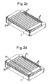
- the vibrating plate is cut by a diamond cutter to a depth greater than the thickness of the vibrating plate to form cut lines whose spacing is, for example, 0.2 mm, corresponding to the desired width of the reed piece, so that slits 20 are formed which pass through outward at least on the side of the conductor bands 8.
- strips 21 are formed from the vibrating plate 10, each strip comprising integrally the metal plate 16, piezoelectric plate 12 and electrode layer 14.
- the strips 21 can never break nor split even under the vibration of the diamond cutter.
- grooves are also formed between the adjacent conductor bands, so that the conductor bands 8 of the base member 2 are separated from each other and become independent terminal portions.
- each of the strips 21 is changed to a vibrating piece in the form of a cantilever whose one end on the side of the conductor bands 8 serves as a fixed end and the other end as a free vibrating end, or, reed pieces 23 are finished.
- a band-shaped member designated by reference numeral 24 is a spacer which is made of a conductive material and provided to set the spacing between the free ends of the reed pieces 23 and nozzle openings 32 in the quiescent state to no more than 200 ⁇ m (to this distance the ink can rise by virtue of surface tension), normally within the range of 5 to 30 ⁇ m.
- the spacer 24 is extended parallel to the arrangement direction of the reed pieces 23 and secured by a conductive adhesive at a position where it gives no influence to the vibration of the reed pieces 23, or in the vicinity of the position facing the conductor bands 8 of the base member 2.
- a member designated by reference numeral 30 is a nozzle forming plate which has one row of nozzle openings 32 formed therein in alignment with the points or free ends of the reed pieces 23.
- each nozzle opening 32 is shaped like a funnel or progressively widened downward on the one side facing the reed piece 23 and on the other side, is protruded from the surface of the nozzle forming plate 30 by a height L.
- the protrusion height L from the surface of the nozzle forming plate 30 be set to 10 to 150 ⁇ m and the thickness D of the nozzle point be set to no more than 150 ⁇ m.
- Such a nozzle opening can be formed concurrently with a substrate forming step by an electro forming process.
- the nozzle forming plate 30 is secured to the surface of the spacer 24 after the distances between the nozzle openings 32 and the free ends of the reed pieces 23 are made uniform. Consequently, the spacing between the reed piece 23 and the nozzle opening 32 is kept to a distance determined by the thickness of the spacer 24, and the respective metal plates 16 of the reed pieces 23 are electrically connected in common by the spacer 24.
- the individual signal wires of a flexible cable for connection with a drive circuit not shown are connected and secured to the corresponding conductor bands 8 of the base member 2, and a common earth wire is connected and secured to the spacer 24.
- This connecting process is carried out to connect the lead wires to the conductor bands 8 of the base member 2, thus is very easy as compared with the process of connecting the signal wires to the reed pieces.
- FIG. 4 shows an embodiment of the ink jet print head including the foregoing drive assembly.
- a casing designated by reference numeral 40 is divided into two chambers 46 and 48 by a partition plate 44 having a through hole 42 formed in a lower section thereof, one chamber 46 serving as an ink tank and the other chamber 48 as a drive assembly accommodating room.
- a wall 50 forming part of the drive assembly accommodating room 48 has a through hole 52 formed therein, the nozzle forming plate 30 of the drive assembly is disposed in tight contact with the through hole 52, and in this condition, the base member 2 is secured to the partition plate 44.
- Reference numeral 55 designates a heater accommodated in the ink tank 46, which is included to maintain the ink temperature at a level best suited for printing.
- the vibration of one reed piece 23 can never influence other adjacent reed pieces 23.
- the individual piezoelectric plates 12 forming part of the corresponding reed pieces 23 are completely separated from each other by the slits 20, any signal to the electrode layer 14 or metal plate 16 of one reed piece 23 can never act on the piezoelectric plate forming part of a different reed piece; thus, no electrical and similar interference is caused.
- the thus configured print head 66 is mounted on a carriage 68 which in turn is seated movably on guide members 62 and 64 disposed parallel to a platen 60. Therefore, while moving in the widthwise direction of a printing paper 65 stretched on the platen surface by a paper bail 67 and a paper feed roller 69, the print head 66 can create dots corresponding to print data by letting fly the ink drops toward the printing paper.
- Fig. 7 shows an embodiment of the structure wherein the electrode layer and metal plate of the reed piece are connected with external signal wires.
- a member designated by reference numeral 70 is configured, similarly to the abovementioned reed piece 23 (Fig. 2d), such that its one surface has a metal plate 74 secured thereto by an eutectic bonding process or using a conductive adhesive and the other surface has an electrode layer 76 formed thereon by an electro forming process or a vapor deposition process.
- a member designated by reference numeral 78 is a base member similar to the abovementioned base member. This member 78 is formed, on its one edge to which the reed piece 70 is secured, with electrically-separated conductor bands 80 and 82 dimensioned so as to divide the width of the reed piece 70 into two.
- a portion, facing the conductor band 82, of the electrode layer 76 of the reed piece is formed with an L-shaped notch 84, this leaving an island-like terminal portion 86 on the end side of the reed piece 70.
- This terminal portion 86 is connected to the metal plate 74 by a conductor member 88 formed so as to cover the end of the reed piece.
- the conductor layer 76 is electrically and mechanically secured to the one conductor band 80, and the metal plate 74 to the other conductor band 82 via the conductor member 88 and the terminal portion 86.
- the lead wires of a cable 90 connected to the opposite ends of the conductor bands 80 and 82, when signals are supplied through the two conductor bands 80 and 82 to the electrode layer 76 and the metal plate 74, the reed piece 70 can curve and recover.
- each reed piece of the above embodiment has been described as a unit member for convenience of explanation, the same result can be obtained by previously forming the terminal portion 86 and the conductor member 88 on the abovementioned vibrating plate (Fig. 2a), securing the base member 78 to the above, and forming slits to divide into the reed pieces.
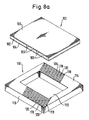
- FIGs. 8a and 8b show a second embodiment of the present invention.
- a member designated by reference numeral 100 is a vibrating plate similar to that shown in Fig. 2a, which is constructed such that an electrode layer 104 is formed on one surface of a thin piezoelectric plate 102, and a metal plate 106 serving as a spring element and an electrode is secured to the other surface so as to ensure conductive relation.
- This vibrating plate 100 has an L-shaped notch, similar to that shown in Fig. 7, formed in its portion facing one, e.g. 118, of paired conductor bands 118 and 120 formed on a base member 110 hereinafter described, this leaving a terminal portion which is connected through a conductor member 103 to the metal plate.
- the base member 110 is made of a rigid and electrical-insulating material, such as glass or ceramic, and formed in its central portion with a rectangular through hole 112.
- the surfaces of two opposing edges 114 and 116 of the base member have two groups of conductor bands 118 and 120 electrically separated from each other, the two occupying the width of each reed piece being formed, that are formed by vapor deposition of metal or printing with conductive adhesive.
- the vibrating plate 100 is disposed such that its one surface where the electrode layer 104 is formed faces the conductor bands 118 and 120 of the base member 110, and then secured to the conductor bands 118 and 120 using a conductive adhesive and to the other two edges using an ordinary adhesive.
- slits 122 are formed at an angle to the direction orthogonal to the arrangement lines A-A and B-B of the nozzle openings, and a second slit 124 is formed so as to pass midway between the two nozzle arrangement lines A-A and B-B. Consequently, the vibrating plate 100 is changed to two groups of separated reed pieces 126 and 128 each having one end secured to either edge 114 or 116 of the base member 110 with the other end being made free.
- each reed piece 126, 128 is connected through a connecting member, a terminal portion, and a conductive adhesive to the conductor band 118, and the electrode layer 104 through an adhesive to the conductor band 120.
- a member designated by reference numeral 130 is a nozzle forming plate which has nozzle openings 132 and 134 formed therein in zigzag form in alignment with the free ends of the reed pieces 126 and 128, and is formed, at its portions coming to contact with the fixed side of the reed pieces, with thick portions 136 to define the spacing between the nozzle openings 132 and 134 and the free ends of the reed pieces.
- the nozzle openings 132 lying on the first arrangement line A-A come to face the free ends of the reed pieces 126 secured to the one edge 114 of the base member 110, and the nozzle openings 134 lying on the second arrangement line B-B come to face the free ends of the reed pieces 128 secured to the other edge 116 of the base member.
- the distance W between the nozzle openings can be cut down, shortening the inter-spacing of the dots; thus, the number of dots creatable per length on the printing paper can be increased. That is, the nozzle openings can be formed or arranged at a pitch smaller than the width of the reed piece.
- the second slit may be formed orthogonally to the first slits.
- the above embodiment includes, instead of using a spacer, the thick portions formed on both edges of the nozzle forming plate to adjust the spacing between the nozzle forming plate and the reed pieces, the same effect can also be obtained by making flat the nozzle forming plate and securing it using a spacer of given thickness.
- a nozzle forming plate 150 as shown in Fig. 9 may be secured to reed pieces 154 by the use of a binding material which is prepared by mixing an adhesive 142 with beads 140 having an outer diameter substantially equal to a desired spacing.
- the spacing between the nozzle openings 152 and the free ends of the reed pieces 154 is defined by the outer diameter of the beads 140, this avoiding the work of interposing a spacer.
Landscapes
- Particle Formation And Scattering Control In Inkjet Printers (AREA)
Applications Claiming Priority (12)
| Application Number | Priority Date | Filing Date | Title |
|---|---|---|---|
| JP309123/88 | 1988-12-07 | ||
| JP30912388A JPH02155651A (ja) | 1988-12-07 | 1988-12-07 | インクジェットヘッド |
| JP3202/89 | 1989-01-10 | ||
| JP3205/89 | 1989-01-10 | ||
| JP320389A JPH02184446A (ja) | 1989-01-10 | 1989-01-10 | インクジェットヘッド |
| JP3203/89 | 1989-01-10 | ||
| JP3201/89 | 1989-01-10 | ||
| JP320589A JP2867405B2 (ja) | 1989-01-10 | 1989-01-10 | インクジェットヘッド |
| JP320489A JPH02184447A (ja) | 1989-01-10 | 1989-01-10 | インクジェットヘッド |
| JP320289A JPH02184445A (ja) | 1989-01-10 | 1989-01-10 | インクジェットヘッド |
| JP3204/89 | 1989-01-10 | ||
| JP320189A JPH02184444A (ja) | 1989-01-10 | 1989-01-10 | インクジェットヘッド |
Publications (3)
| Publication Number | Publication Date |
|---|---|
| EP0372521A2 true EP0372521A2 (fr) | 1990-06-13 |
| EP0372521A3 EP0372521A3 (en) | 1990-12-05 |
| EP0372521B1 EP0372521B1 (fr) | 1993-04-14 |
Family
ID=27547753
Family Applications (1)
| Application Number | Title | Priority Date | Filing Date |
|---|---|---|---|
| EP89122478A Expired - Lifetime EP0372521B1 (fr) | 1988-12-07 | 1989-12-06 | Tête d'impression à jet d'encre fonctionnant à la demande |
Country Status (3)
| Country | Link |
|---|---|
| US (1) | US5072240A (fr) |
| EP (1) | EP0372521B1 (fr) |
| DE (1) | DE68906001T2 (fr) |
Cited By (8)
| Publication number | Priority date | Publication date | Assignee | Title |
|---|---|---|---|---|
| EP0484983A3 (en) * | 1990-11-09 | 1993-02-24 | Seiko Epson Corporation | Ink-jet recording head and its use |
| AU646351B2 (en) * | 1991-08-16 | 1994-02-17 | Compaq Computer Corporation | High density ink jet printhead |
| EP0600743A3 (fr) * | 1992-12-04 | 1994-08-31 | Ngk Insulators Ltd | |
| US5444471A (en) * | 1990-02-23 | 1995-08-22 | Seiko Epson Corporation | Drop-on-demand ink-jet printing head |
| EP0678384A1 (fr) | 1990-02-23 | 1995-10-25 | Seiko Epson Corporation | Tête d'impression à jet d'encre générant des gouttelettes à la demande |
| EP0723866A4 (fr) * | 1993-10-14 | 1997-03-26 | Citizen Watch Co Ltd | Tete a jet d'encre, son procede de production et procede de commande associe |
| RU2141408C1 (ru) * | 1996-01-22 | 1999-11-20 | Таунджет Корпорейшн ПТИ, Лтд. | Плата сопла для струйного принтера |
| US6186619B1 (en) | 1990-02-23 | 2001-02-13 | Seiko Epson Corporation | Drop-on-demand ink-jet printing head |
Families Citing this family (39)
| Publication number | Priority date | Publication date | Assignee | Title |
|---|---|---|---|---|
| JP2841750B2 (ja) * | 1989-07-03 | 1998-12-24 | セイコーエプソン株式会社 | オンデマンド型インクジェット印字ヘッド |
| ES2100278T3 (es) * | 1991-01-18 | 1997-06-16 | Canon Kk | Unidad para chorros de liquido con orificios y aparato de impresion que utiliza la misma. |
| JP2867740B2 (ja) * | 1991-05-31 | 1999-03-10 | ブラザー工業株式会社 | 液滴噴射装置 |
| JP2744535B2 (ja) * | 1991-07-08 | 1998-04-28 | 株式会社テック | インクジェットプリンタヘッドの製造方法 |
| CA2075786A1 (fr) * | 1991-08-16 | 1993-02-17 | John R. Pies | Methode de fabrication d'une tete a imprimer a jet d'encre sous pression |
| JP3103404B2 (ja) * | 1991-10-22 | 2000-10-30 | キヤノン株式会社 | インクジェット記録ヘッドの製造方法、インクジェット記録ヘッドおよびインクジェット記録装置 |
| EP0795404B1 (fr) * | 1991-12-26 | 2005-06-08 | Seiko Epson Corporation | Tête d'enregistrement à jet d'encre |
| US5764257A (en) | 1991-12-26 | 1998-06-09 | Seiko Epson Corporation | Ink jet recording head |
| US5208980A (en) * | 1991-12-31 | 1993-05-11 | Compag Computer Corporation | Method of forming tapered orifice arrays in fully assembled ink jet printheads |
| US5552813A (en) * | 1992-03-11 | 1996-09-03 | Rohm Co., Ltd. | Ink jet head with nozzle arrangement to reduce viscous drag |
| US5703631A (en) * | 1992-05-05 | 1997-12-30 | Compaq Computer Corporation | Method of forming an orifice array for a high density ink jet printhead |
| US5440332A (en) * | 1992-07-06 | 1995-08-08 | Compa Computer Corporation | Apparatus for page wide ink jet printing |
| JP3318687B2 (ja) * | 1993-06-08 | 2002-08-26 | 日本碍子株式会社 | 圧電/電歪膜型素子及びその製造方法 |
| US5983471A (en) * | 1993-10-14 | 1999-11-16 | Citizen Watch Co., Ltd. | Method of manufacturing an ink-jet head |
| US5793149A (en) * | 1995-07-26 | 1998-08-11 | Francotyp-Postalia Ag & Co. | Arrangement for plate-shaped piezoactuators and method for the manufacture thereof |
| NL1004016C2 (nl) * | 1996-09-12 | 1998-03-13 | Oce Tech Bv | Inktstraal-drukkop. |
| US6002549A (en) * | 1996-11-01 | 1999-12-14 | Seagate Technology, Inc. | Dither microactors for stiction release in magnetic disc drives |
| WO1998020486A1 (fr) * | 1996-11-01 | 1998-05-14 | Seagate Technology, Inc. | Bras de commande a microcommande piezoelectrique integree |
| JP3697829B2 (ja) * | 1997-04-09 | 2005-09-21 | ブラザー工業株式会社 | インクジェットヘッドの製造方法 |
| US6396667B1 (en) | 1997-06-24 | 2002-05-28 | Seagate Technology Llc | Electromagnetic disc drive microactuator and suspension |
| US6269687B1 (en) | 1997-09-22 | 2001-08-07 | Seagate Technology Llc | Force sensing slider |
| US6067215A (en) | 1997-10-09 | 2000-05-23 | Seagate Technology, Inc. | Magnetic shielding for electromagnetic microactuator |
| US6163434A (en) * | 1997-10-23 | 2000-12-19 | Seagate Technology Llc | Piezoresistive position sensors embedded in disc drive microactuator |
| US6078473A (en) * | 1998-05-13 | 2000-06-20 | Seagate Technology, Inc. | Gimbal flexure for use with microactuator |
| JP3381779B2 (ja) * | 1998-09-17 | 2003-03-04 | セイコーエプソン株式会社 | 圧電振動子ユニット、圧電振動子ユニットの製造方法、及びインクジェット式記録ヘッド |
| US6417600B2 (en) * | 1998-09-17 | 2002-07-09 | Seiko Epson Corporation | Piezoelectric vibrator unit, method for manufacturing the same, and ink jet recording head comprising the same |
| US6033079A (en) | 1999-03-15 | 2000-03-07 | Hudyma; Russell | High numerical aperture ring field projection system for extreme ultraviolet lithography |
| JP2000348321A (ja) * | 1999-06-03 | 2000-12-15 | Nec Corp | 磁気ディスク装置,磁気ヘッド,磁気ヘッドの製造方法および磁気ディスク装置の製造方法 |
| DE10039255B4 (de) * | 2000-08-11 | 2004-02-12 | Tally Computerdrucker Gmbh | Tropfenerzeuger für Mikrotropfen, insbesondere für den Düsenkopf eines Tintendruckers |
| AU2004226968B2 (en) * | 2000-10-20 | 2005-08-18 | Zamtec Limited | Miniscus seal for inkjet nozzles |
| US6457809B1 (en) * | 2000-10-20 | 2002-10-01 | Silverbrook Research Pty Ltd | Drop flight correction for moving nozzle ink jet |
| DE60238183D1 (de) * | 2001-04-06 | 2010-12-16 | Ngk Insulators Ltd | Mehrschlitzstellglied, tintenstrahlkopf und verfahren zur herstellung des mehrschlitzstellglieds |
| DE10133939C2 (de) * | 2001-07-12 | 2003-11-06 | Tally Computerdrucker Gmbh | Verfahren zum Herstellen eines Tropfenerzeugers für Mikrotropfen, insbesondere eines Düsenkopfes für Tintendrucker und Tropfenerzeuger |
| US6953241B2 (en) * | 2001-11-30 | 2005-10-11 | Brother Kogyo Kabushiki Kaisha | Ink-jet head having passage unit and actuator units attached to the passage unit, and ink-jet printer having the ink-jet head |
| US6814425B2 (en) * | 2002-04-12 | 2004-11-09 | Hewlett-Packard Development Company, L.P. | Droplet placement onto surfaces |
| US6764023B2 (en) * | 2002-10-09 | 2004-07-20 | Industrial Technology Research Institute | Bi-direction pumping droplet mist ejection apparatus |
| JP4670225B2 (ja) * | 2003-04-04 | 2011-04-13 | セイコーエプソン株式会社 | 圧電素子形成部材およびその製造方法ならびにそれを用いた圧電素子ユニットおよび液体噴射ヘッド |
| TWI280895B (en) * | 2003-11-24 | 2007-05-11 | Ind Tech Res Inst | Micro-droplet injection device with automatic balance of negative pressure |
| JP2020082444A (ja) * | 2018-11-21 | 2020-06-04 | セイコーエプソン株式会社 | インクジェットヘッド |
Family Cites Families (8)
| Publication number | Priority date | Publication date | Assignee | Title |
|---|---|---|---|---|
| DE2527647C3 (de) * | 1975-06-20 | 1981-06-25 | Siemens AG, 1000 Berlin und 8000 München | Mit Flüssigkeitströpfchen arbeitendes Schreibgerät |
| DE2905063A1 (de) * | 1979-02-10 | 1980-08-14 | Olympia Werke Ag | Anordnung zur vermeidung des ansaugens von luft durch die duesen eines spritzsystems |
| DE3245283A1 (de) * | 1982-12-07 | 1984-06-07 | Siemens AG, 1000 Berlin und 8000 München | Anordnung zum ausstoss von fluessigkeitstroepfchen |
| JPS6116867A (ja) * | 1984-05-29 | 1986-01-24 | Yasuhiko Ogawa | 櫛型の圧電駆動装置 |
| GB8507688D0 (en) * | 1985-03-25 | 1985-05-01 | Lane International Ltd John | Fluid applicator |
| US4768266A (en) * | 1986-08-29 | 1988-09-06 | Dataproducts Corporation | Method of making an ink jet printer transducer array |
| JPS63222859A (ja) * | 1987-03-11 | 1988-09-16 | Nec Corp | ドロツプオンデマンドインクジエツトヘツド |
| EP0337429B1 (fr) * | 1988-04-12 | 1993-07-07 | Seiko Epson Corporation | Tête à jet d'encre |
-
1989
- 1989-12-06 EP EP89122478A patent/EP0372521B1/fr not_active Expired - Lifetime
- 1989-12-06 US US07/446,734 patent/US5072240A/en not_active Expired - Fee Related
- 1989-12-06 DE DE8989122478T patent/DE68906001T2/de not_active Expired - Fee Related
Cited By (21)
| Publication number | Priority date | Publication date | Assignee | Title |
|---|---|---|---|---|
| EP0873872A1 (fr) * | 1990-02-23 | 1998-10-28 | Seiko Epson Corporation | Tête d'impression à jet d'encre générant des gouttelettes à la demande |
| EP1055519A1 (fr) * | 1990-02-23 | 2000-11-29 | Seiko Epson Corporation | Tête d'impression à jet d'encre générant des gouttelettes à la demande |
| US6942322B2 (en) | 1990-02-23 | 2005-09-13 | Seiko Epson Corporation | Drop-on-demand ink-jet printing head |
| US6742875B2 (en) | 1990-02-23 | 2004-06-01 | Seiko Epson Corp | Drop-on-demand ink-jet printing head |
| US5444471A (en) * | 1990-02-23 | 1995-08-22 | Seiko Epson Corporation | Drop-on-demand ink-jet printing head |
| EP0678384A1 (fr) | 1990-02-23 | 1995-10-25 | Seiko Epson Corporation | Tête d'impression à jet d'encre générant des gouttelettes à la demande |
| US5600357A (en) * | 1990-02-23 | 1997-02-04 | Seiko Epson Corporation | Drop-on-demand ink-jet printing head |
| EP1208983A2 (fr) | 1990-02-23 | 2002-05-29 | Seiko Epson Corporation | Tête d'impression jet d'encre générant des gouttelettes sur demande |
| US6186619B1 (en) | 1990-02-23 | 2001-02-13 | Seiko Epson Corporation | Drop-on-demand ink-jet printing head |
| EP0655334B1 (fr) * | 1990-02-23 | 1997-07-23 | Seiko Epson Corporation | Tête d'impression à jet d'encre générant des gouttelettes à la demande |
| US5910809A (en) * | 1990-02-23 | 1999-06-08 | Seiko Epson Corporation | Drop-on-demand ink-jet printing head |
| US5894317A (en) * | 1990-02-23 | 1999-04-13 | Seiko Epson Corporation | Drop-on-demand ink-jet printing head |
| EP0484983A3 (en) * | 1990-11-09 | 1993-02-24 | Seiko Epson Corporation | Ink-jet recording head and its use |
| US5252994A (en) * | 1990-11-09 | 1993-10-12 | Seiko Epson Corporation | Ink-jet recording head |
| AU646351B2 (en) * | 1991-08-16 | 1994-02-17 | Compaq Computer Corporation | High density ink jet printhead |
| US5617127A (en) * | 1992-12-04 | 1997-04-01 | Ngk Insulators, Ltd. | Actuator having ceramic substrate with slit(s) and ink jet print head using the actuator |
| EP0600743A3 (fr) * | 1992-12-04 | 1994-08-31 | Ngk Insulators Ltd | |
| EP0897802A3 (fr) * | 1993-10-14 | 1999-03-10 | Citizen Watch Co. Ltd. | Tête à jet d'encre et procédés pour sa fabrication et son actionnement |
| EP0897803A3 (fr) * | 1993-10-14 | 1999-03-10 | Citizen Watch Co. Ltd. | Tête à jet d'encre et procédés pour sa fabrication et son actionnement |
| EP0723866A4 (fr) * | 1993-10-14 | 1997-03-26 | Citizen Watch Co Ltd | Tete a jet d'encre, son procede de production et procede de commande associe |
| RU2141408C1 (ru) * | 1996-01-22 | 1999-11-20 | Таунджет Корпорейшн ПТИ, Лтд. | Плата сопла для струйного принтера |
Also Published As
| Publication number | Publication date |
|---|---|
| EP0372521B1 (fr) | 1993-04-14 |
| EP0372521A3 (en) | 1990-12-05 |
| US5072240A (en) | 1991-12-10 |
| DE68906001D1 (de) | 1993-05-19 |
| DE68906001T2 (de) | 1993-09-09 |
Similar Documents
| Publication | Publication Date | Title |
|---|---|---|
| EP0372521B1 (fr) | Tête d'impression à jet d'encre fonctionnant à la demande | |
| EP0337429B1 (fr) | Tête à jet d'encre | |
| EP0516188B1 (fr) | Tête d'impression à jet d'encre générant des gouttelettes à la demande | |
| US4536097A (en) | Piezoelectrically operated print head with channel matrix and method of manufacture | |
| EP0576037B1 (fr) | Tête d'enregistrement à jet d'encre | |
| HK1000572B (en) | Drop-on-demand ink-jet printing head | |
| HK1002427B (en) | Drop-on-demand ink jet printing head | |
| US6942322B2 (en) | Drop-on-demand ink-jet printing head | |
| US4334232A (en) | Laminated charge plate for an ink jet printing device and method of manufacturing same | |
| EP0678384B1 (fr) | Tête d'impression à jet d'encre générant des gouttelettes à la demande | |
| JP4243341B2 (ja) | インクジェットヘッド | |
| JP2002011878A (ja) | アクチュエータユニット及びインクジェット式記録ヘッド | |
| HK1000440B (en) | Drop-on-demand ink-jet printing head | |
| HK1051989A (en) | Drop-on-demand ink-jet printing head | |
| HK1000416B (en) | Ink-jet recording head | |
| HK1000416A1 (en) | Ink-jet recording head |
Legal Events
| Date | Code | Title | Description |
|---|---|---|---|
| PUAI | Public reference made under article 153(3) epc to a published international application that has entered the european phase |
Free format text: ORIGINAL CODE: 0009012 |
|
| AK | Designated contracting states |
Kind code of ref document: A2 Designated state(s): DE FR GB IT |
|
| PUAL | Search report despatched |
Free format text: ORIGINAL CODE: 0009013 |
|
| AK | Designated contracting states |
Kind code of ref document: A3 Designated state(s): DE FR GB IT |
|
| 17P | Request for examination filed |
Effective date: 19901221 |
|
| 17Q | First examination report despatched |
Effective date: 19920903 |
|
| GRAA | (expected) grant |
Free format text: ORIGINAL CODE: 0009210 |
|
| AK | Designated contracting states |
Kind code of ref document: B1 Designated state(s): DE FR GB IT |
|
| ITF | It: translation for a ep patent filed | ||
| REF | Corresponds to: |
Ref document number: 68906001 Country of ref document: DE Date of ref document: 19930519 |
|
| ET | Fr: translation filed | ||
| PLBE | No opposition filed within time limit |
Free format text: ORIGINAL CODE: 0009261 |
|
| STAA | Information on the status of an ep patent application or granted ep patent |
Free format text: STATUS: NO OPPOSITION FILED WITHIN TIME LIMIT |
|
| 26N | No opposition filed | ||
| PGFP | Annual fee paid to national office [announced via postgrant information from national office to epo] |
Ref country code: GB Payment date: 19971127 Year of fee payment: 9 |
|
| PGFP | Annual fee paid to national office [announced via postgrant information from national office to epo] |
Ref country code: FR Payment date: 19971209 Year of fee payment: 9 |
|
| PGFP | Annual fee paid to national office [announced via postgrant information from national office to epo] |
Ref country code: DE Payment date: 19971212 Year of fee payment: 9 |
|
| PG25 | Lapsed in a contracting state [announced via postgrant information from national office to epo] |
Ref country code: GB Free format text: LAPSE BECAUSE OF NON-PAYMENT OF DUE FEES Effective date: 19981206 |
|
| GBPC | Gb: european patent ceased through non-payment of renewal fee |
Effective date: 19981206 |
|
| PG25 | Lapsed in a contracting state [announced via postgrant information from national office to epo] |
Ref country code: FR Free format text: LAPSE BECAUSE OF NON-PAYMENT OF DUE FEES Effective date: 19990831 |
|
| REG | Reference to a national code |
Ref country code: FR Ref legal event code: ST |
|
| PG25 | Lapsed in a contracting state [announced via postgrant information from national office to epo] |
Ref country code: DE Free format text: LAPSE BECAUSE OF NON-PAYMENT OF DUE FEES Effective date: 19991001 |
|
| PG25 | Lapsed in a contracting state [announced via postgrant information from national office to epo] |
Ref country code: IT Free format text: LAPSE BECAUSE OF NON-PAYMENT OF DUE FEES;WARNING: LAPSES OF ITALIAN PATENTS WITH EFFECTIVE DATE BEFORE 2007 MAY HAVE OCCURRED AT ANY TIME BEFORE 2007. THE CORRECT EFFECTIVE DATE MAY BE DIFFERENT FROM THE ONE RECORDED. Effective date: 20051206 |