EP0372558A2 - Appareil de fixage d'une image - Google Patents
Appareil de fixage d'une image Download PDFInfo
- Publication number
- EP0372558A2 EP0372558A2 EP89122594A EP89122594A EP0372558A2 EP 0372558 A2 EP0372558 A2 EP 0372558A2 EP 89122594 A EP89122594 A EP 89122594A EP 89122594 A EP89122594 A EP 89122594A EP 0372558 A2 EP0372558 A2 EP 0372558A2
- Authority
- EP
- European Patent Office
- Prior art keywords
- film
- heater
- fixing
- image
- recording material
- Prior art date
- Legal status (The legal status is an assumption and is not a legal conclusion. Google has not performed a legal analysis and makes no representation as to the accuracy of the status listed.)
- Granted
Links
Images


Classifications
-
- G—PHYSICS
- G03—PHOTOGRAPHY; CINEMATOGRAPHY; ANALOGOUS TECHNIQUES USING WAVES OTHER THAN OPTICAL WAVES; ELECTROGRAPHY; HOLOGRAPHY
- G03G—ELECTROGRAPHY; ELECTROPHOTOGRAPHY; MAGNETOGRAPHY
- G03G15/00—Apparatus for electrographic processes using a charge pattern
- G03G15/20—Apparatus for electrographic processes using a charge pattern for fixing, e.g. by using heat
- G03G15/2003—Apparatus for electrographic processes using a charge pattern for fixing, e.g. by using heat using heat
- G03G15/2014—Apparatus for electrographic processes using a charge pattern for fixing, e.g. by using heat using heat using contact heat
- G03G15/2064—Apparatus for electrographic processes using a charge pattern for fixing, e.g. by using heat using heat using contact heat combined with pressure
Definitions
- the present invention relates to an image fixing apparatus for heating and fixing a toner image on a recording material, usable with an image forming apparatus such as an electrophotographic machine or an electrostatic recording machine.
- the recording material supporting an unfixed toner image is passed through a nip formed between a heating roller maintained at a predetermined temperature and a pressing or back-up roller having an elastic layer and press-contacted to the heating roller.
- the conventional image fixing system of this type requires that the heating roller is always maintained at an optimum temperature, so that the thermal capacity of the heating roller has to be large to prevent the temperature variation. Therefore, the time period required for the warming of the apparatus is long, and in addition, the power consumption is large.
- U.S. Patent No. 3,578,797 proposes an image fixing apparatus wherein the toner image is fused by heat from a heating roller through an endless belt.
- U.S. Serial No. 206,767 which has been assigned to the assignee of this application proposes a novel image fixing apparatus wherein the use is made with a thin endless film and a fixed heater having a low thermal capacity, by which the warming period is significantly reduced or eliminated.
- the image fixing system using the endless belt as disclosed in the U.S. Patent or the U.S. Application, imparts driving force or tension by a roller or rollers to constitute an endless travel path, the belt or the film is laterally deviated or shifted (in a direction perpendicular to the movement of the endless belt).
- the number of the rollers is increased to reduce the intervals between the rollers, or that the precision of the constituents part is increased, by which the lateral shift of the film is suppressed to a certain extent.
- they would result in increase of the cost, and in the inability of mass-production.
- the image fixing apparatus comprises a heater 20 having a low thermal capacity and fixed in the fixing apparatus and an image fixing film 25 in the form of an endless belt contacted to the heater 20 and movable in the direction indicated by an arrow.
- a driving roller 26 and a follower roller 26 in part driving force and tension to the fixing film 25 and constitutes a path of the film movement.
- a pressing roller includes a rubber elastic layer having a good releasing property, made of silicone rubber or the like, and rotates while pressing the fixing film 25 to the heater 20.
- the recording material (not shown) carrying thereon an unfixed toner image is introduced into a fixing position (nip) N, where the unfixed image is fixed.
- a detecting element 70 such as a photosensor to detect the lateral position of the film.
- control means controls an eccentric cam 78, as indicated by the chain line 78′, so as to displace one longitudinal end of a follower roller, as indicated by a chain line 27′ to control the lateral position of the fixing film. More particularly, when the fixing film 25 starts to shift in one direction to such an extent that the detecting element 70 detects it, the follower roller 27 is displaced at one end or inclined to apply to the fixing film 25 force in the opposite direction.
- the fixing film 25 is driven while its lateral position is maintained with a predetermined range (in the region between the detecting elements 70 at the both sides in this embodiment).
- the shift of the fixing film 25 can be controlled without changing the heating conditions in the fixing position N.
- the follower roller 27 is displaced by an eccentric cam 78 substantially vertical direction.
- the direction of the displacement is not limited to this.
- the substantially vertical movement is preferable for the following reasons.
- the follower roller 27 receives the tension force by the tension spring 79 in order to drive the fixing film 25 without crease, and in addition, the fixing position N is heated, and therefore, larger displacing force is required in order to displace it substantially in the direction which is the same as the direction of the tension force, and the fixing film 25 can be elongated or creased by the sheet.
- the roller to be displaced is not limited to the follower roller 27, but it is possible to displace the driving roller 26 to control the shift of the fixing film 25.
- the driving means has to include additional mechanism such as swinging mechanism, and therefore, the cost may be increased.
- the roller to be shifted is desirable upstream of the fixing position N. This is because at the downstream side of the fixing position N, the recording material discharged from the fixing position N has to be separated from the fixing film 25, and therefore, if the roller is displaced downstream of the fixing position N, particularly adjacent to the separating position, the separation action at the separating position S may be influenced in the separation angle and the precise separating position. If the shifting force is applied extremely at the separating position S, the separating conditions can be changed by the crease of the film, with the result that the improper separation, jam or the toner off-set to the fixing film 25 easily occur. Therefore, the position of the displaceable roller is preferably upstream of the fixing position N and downstream of the driving roller 26, with the driving roller 26 stationary.
- a separate member 71 which is displaceable is used to control the lateral shift.
- Figure 2 also shows another method of displacing the displaceable roller, by a solenoid 72 via lever 73.
- the detector 70 may include a lever or levers disposed close to the lateral end or ends of the fixing film 25 to detect the position of the film.
- the amount and timing of the displacement are selected in accordance with various conditions of the respective members.
- the detecting position, the number of detecting positions and the displacing conditions may be determined in accordance with the size of the apparatus.
- the stabilized driving of the fixing film is accomplished without influence to the fixing position.
- Figure 3 is a sectional view of an exemplary image forming apparatus provided with an image heating and fixing apparatus 11 according to an embodiment of the present invention.
- Image forming apparatus in this embodiment is an electrophotographic copying machine wherein an original supporting platen is reciprocable, and which includes a rotatable drum and which is of an image transfer type.
- the image forming apparatus comprises a casing 100, an original supporting platen 1 of a reciprocable type including a transparent member made of glass plate or the like on a top plate 100a of the casing 100, wherein the original supporting platen is reciprocable on the top plate 100a in the rightward direction a and in the leftward direction a′ at the predetermined speeds.
- Designated by a reference G is an original to be copied, it is placed face-down on the top surface of the original supporting platen at a predetermined original reference position and is covered by an original pressing plate 1a.
- a slit opening 100b is formed in the top plate 100a, extending in a direction perpendicular to the reciprocal direction of the original supporting platen 1 (perpendicular to the sheet of the drawing).
- the image surface of the original G on the original supporting platen 1 passes gradually by the slit opening 100b from its right side during the rightward stroke a of the reciprocable movement.
- the original is scanned by light L from a lamp 7 through a slit opening 100b and through the original transparent original supporting platen 1.
- the light reflected by the scanning illumination light is formed on a surface of a photosensitive drum 3 through an array 2 of short focus and small diameter imaging elements.
- the photosensitive drum 3 has a coated photosensitive layer made of a photosensitive material such as zinc oxide or organic photoconductor, and is rotatable in the clockwise direction b at a predetermined speed about a central shaft 3a. During the rotation, it is uniformly charged to a positive or negative polarity by a charger 4. The surface having been uniformly charged is exposed to the light image of the original (slit exposure), so that an electrostatic latent image is formed on the photosensitive drum 3.
- a coated photosensitive layer made of a photosensitive material such as zinc oxide or organic photoconductor
- the electrostatic latent image is developed by a developing device 5 into a visualized image with toner made of resin which is softened or fused by heating and other material or materials.
- the toner image (visualized image) is advanced to an image transfer station having an image transfer discharger 8.
- the transfer material sheet P (recording material) are accommodated in a cassette S. From the cassette, the sheets are fed out one-by-one by a pick-up roller 6. The sheet P is then fed to the transfer discharger 8 by the registration roller 9 in such a timed relation that when the leading edge of the toner image on the drum reaches the transfer discharger 8, the leading edge of the transfer material sheet P reaches the transfer discharger 8 so that they are aligned. Then, the toner image is transferred from the photosensitive drum 3 onto the fed sheet by the transfer discharger 8.
- the sheet having received the toner image is separated from the photosensitive drum 3 by an unshown separating means, and is conveyed to a fixing device 11 by a conveying device 10.
- a fixing device 11 which will be described in detail hereinafter, in the unfixed toner image is heated and fixed, and finally, it is discharged onto the discharge tray 12 through a guide 35 and discharging rollers 36.
- FIG. 4 is an enlarged view of the fixing apparatus 11.
- An endless fixing film 25 is stretched around a left side driving roller 26, a right side follower roller 27, a low thermal capacity linear heater 20 fixed at a lower position between the rollers 26 and 27 and a guide roller 26a disposed below the driving roller 26, the rollers 26 and 27, the heater 20 and the guiding roller 26a being extended parallel to each other.
- the follower roller 27 functions as a tension roller for applying tension to the endless fixing film 25.
- the fixing film 25 is rotationally driven without crease, snaking movement and delay, at a peripheral speed which is substantially the same as the transfer sheet P having thereon the unfixed toner image Ta supplied from the image forming station 8.
- a pressing roller 28 functioning as a member for urging the sheet has a rubber elastic layer having a good releasing property, made of silicone rubber or the like. It presses the bottom travel of the endless fixing film 25 to the bottom surface of the heater 20, by an unshown urging means, with the total pressure of 4 - 7 kg. It rotates in the same peripheral direction as the transfer sheet P, that is, in the counterclockwise direction.
- the endless fixing film 25 is repeatedly used for the heat-fixing the toner image, it is good in the heat resistivity, the releasing property and the durability. Generally, it has a thickness of not more than 100 microns, preferably not more than 50 microns.
- heat-resistive resin such as polyimide, polyetherimide, PES or PFA (copolymer of tetrafluoroethylene and perfluoroalkyl vinyl ether) or a compound layer film including a film having a thickness of 20 microns and a releasing coating layer of 10 microns, at least at the image contacting side of the film, including fluorinated resin such as PTFE (tetrafluoroethylene resin) or P
- a heater supporting member 24 is heat-resistive, and provides the entire mechanical strength of the heater 20. It is made of a highly heat-resistive resin such as PTS (polyphenylene sulfide), PAI (polyamide imide), PI (polyimide), PEEK (polyester ester ketone) or liquid crystal polymer or a compound material including such a resin and ceramic material or glass.
- a highly heat-resistive resin such as PTS (polyphenylene sulfide), PAI (polyamide imide), PI (polyimide), PEEK (polyester ester ketone) or liquid crystal polymer or a compound material including such a resin and ceramic material or glass.
- a base plate 21 for the heater is, for example, alumina base plate having a thickness of 1.0 mm, a width of 10 mm and a length of 240 mm.
- a heat generating element is in the form of a line or stripe having a low thermal capacity, for example. It has, for example, a width of 1.0 mm and is extended along the length of the base plate 21 substantially at the middle thereof. It is made of, for example, Ta2N or other elastic resistance material which generates heat upon electric energization.
- a temperature detecting element 23, for example, is a low thermal capacity temperature measuring resistor such as Pt film applied by screen printing or the like along the length substantially at the center of the top surface (opposite from the surface having the heat generating element 22) of the base plate 21.
- the linear or stripe heat generating element 22 is supplied with electric power by the electric connections at the longitudinal ends to generate heat along the entire length of the heat generating element 22.
- the energization is performed through an energization control circuit so that DC 100 V pulses are applied at the period of 20 msec with the pulse width being changed in accordance with the temperature detected by the temperature detecting element 23.
- the pulse width is controlled within the range of 0.5 - 5 msec, and the heat generating element 22 is instantaneously heated up to 200 - 300 o C each time the pulse is applied.
- there is a sensor (not shown) for sensing the leading and trailing edges of the sheet adjacent to the fixing device at its upstream side with respect to the transfer sheet conveyance direction. Using the detection signal by the sensor, the energization period for the heat generating element 22 is limited to the period in which the sheet P is passing through the fixing device 11.
- the image forming apparatus formed an image and feeds the sheet from the transfer station 8 to the fixing device 11.
- the fixing film 25 starts to rotate or travel.
- the transfer sheet P is guided along the guide 29, and is introduced into the nip N (fixing nip) between the fixing sheet 25 and the pressing roller 28, by which the toner carrying side of the sheet P is closely contacted to the bottom surface of the fixing film moving at the same speed at the sheet P, and they are passed together through the nip without surface deviation or crease.
- the heat generating element 22 has a width W which is within the fixing nip N formed between the bottom surface of the heater 20 and the pressing roller 28.
- the image carrying surface of the sheet P is heated from the heat generating element 22 through the fixing film 24 while it is passed through the nip N while being in press-contacted to the fixing film surface, and the toner image is fused at the high temperature, and it is softened or bonded on the sheet P as a softened or bonded toner image Tb.
- the separation between the sheet P (the recording material) and the fixing film 24 is effected after the sheet P has passed through the fixing nip N.
- the temperature of the toner Tb is higher than the glass transition point, and therefore, the bonding force between the sheet P and the fixing film 25 is small at the separation point, and therefore, the sheet P is always smoothly separated with hardly any toner off-set to the fixing film 25 and without the sheet P sticks to the fixing film 25 and without the resulting jamming.
- the toner Tb at the temperature higher than the glass transition point has proper rubber characteristics so that the toner image at the separating point does not follow the surface of the fixing film, and therefore, it has a sufficiently rough surface property. Then, the toner is cooled and solidified without changing the surface property. Therefore, the toner image fixed is not glossy, and has a high quality.
- the sheet P separated from the fixing film 25 is guided by the guide 35 and is conveyed to the couple of discharging rollers 36. During the conveyance, the temperature of the toner Tb decreases from the temperature higher than the glass transition point by spontaneous cooling, and is solidified into a solidified toner image To. The sheet P thus having the fixed toner image is discharged to the tray 12.
- the linear heat generating element 22 of the heater 20 is instantaneously heated upon energization to a sufficiently high temperature in consideration of the toner fusing point (or fixable temperature), and therefore, it is not necessary to keep the heat generating element energized during the stand-by state of the apparatus. Therefore, only little heat is transferred to the pressing roller 28 when the fixing operation is not carried out.
- the fixing operation in the fixing nip N between the heater 20 and the pressing roller 28, the fixing film, the toner image and the sheet P are disposed, and the heating period is short. For those reasons, there exists a steep temperature gradient. Therefore, the pressing roller 28 is not easily heated, and therefore, the temperature thereof is maintained lower than the toner fusing point even when a practically continuous image forming operation is performed.
- the toner image made of the heat fusible toner on the sheet P is first heated and fused by the heater 20 through the fixing film, and particularly, the surface layer of the toner is completely softened and fused.
- the heater, the fixing film, the toner image and the sheet are urged by the pressing roller 28, so that the heat is efficiently transferred.
- the toner image can be efficiently heated and fused with minimum heating of the sheet P itself.
- the energization period is limited. For those reasons, the energy consumption can be saved.
- the size of the heater may be small, and therefore, the thermal capacity may be small. Therefore, it is not necessary to pre-energize the heater increasing the stand-by period. The power consumption during the non-fixing-operation can be reduced, and in addition, the temperature rise within the apparatus can be prevented.
- first and second film position detecting means 51 and 52 are disposed at a front and rear side of the fixing film, namely, bottom side and top side in Figure 5. They are, for example, photointerruptors photoreflectors or the like.
- the film 25 is stretched around the driving roller 26, the follower roller 27, the heater 20 and the guide roller 26a.
- the entirety of the fixing film 25 shifts toward the front side (A), and the amount of shifts exceeds a tolerance
- the front side edge 25a of the film is detected by the first film position detecting means 51, and the event is transmitted to the control circuit.
- the rear edge 25b of the film 25 is detected by the second film position detecting means 52, and the event is transmitted to the control circuit.
- a control mechanism 53 for controlling the shift of the fixing film 25 is associated with a bearing 27a at the front side of the follower roller 27 and functions to horizontally displace it toward (X) and away (Y) from the driving roller 26.
- a belt-like member tends to shift toward a side where a distance between shafts around which the belt is stretched is smaller.
- the control mechanism utilizes this tendency.
- the bearing 27a of the follower roller 27 at the front side is moved toward (X) the driving roller 26, the fixing film 25 shifts entirely toward the front side (A).
- the fixing film 25 moves entirely toward the rear side (B).
- the shift controlling mechanism moves the bearing 27a of the follower roller 27 toward the front side (Y), so that the front shift of the fixing film 25 is corrected.
- the bearing 27a is moved in the direction X, by which the rear shift of the fixing film 25 is corrected.
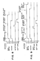
- Figures 6 and 7 are a timing chart and a control sequence of the film 25 shift control.
- the main motor starts to rotate, and simultaneously therewith or after a certain delay, the driving roller 26 is driven, and the heater 20 (22) is energized and controlled.
- the first and second position detecting means 51 and 52 detect the shift of the fixing film 25, and if the shift beyond the tolerance is detected, the mechanism 53 immediately controls the fixing film 25 in response to the detection signal.
- the transfer sheet P is introduced into the fixing apparatus 11, and the fixing operation is carried out.
- the vibration of the fixing film resulting from the shift control does not influence the transfer sheet P, and since the fixing film 25 is positioned in place before the fixing operation starts, good images can be obtained.
- the shift control is not performed, and the fixing operation is directly started.
- the fixing film 25 is maintained at correct position during the fixing operations, and therefore, a good fixed image can be provided, and simultaneously, the production of crease or the like of fixing film attributable to the lateral shift of the fixing film 25, is prevented.
- the shift control operation is performed during a pre-rotation period of an image formation cycle, that is, during the period in which the fixing operation is not performed, and the recording material is not passed through the fixing apparatus. It may be performed during a post-rotation period after the image formation.
- Figure 8 shows a timing chart in that case. Where the shift control is performed during the post-rotation, the time period for the pre-rotation can be shortened, and therefore, the time required for the first image formation can be reduced.
- the shift control may be performed between adjacent fixing operations, that is, during the interval between the succeeding sheets.
- Figure 9 is a timing chart in that case.
- Figure 10 shows a timing chart, in which the pre-rotation shift control and the interval shift control are combined, or in which the interval shift control and the post-rotation shift control are combined.
- the shift control mechanism 53 is effective to change the distance between the shafts at one side. But it may be in the form of an mechanism for moving the follower roller 27 in a skewed position.
- the point of time for detecting the shift may be during the passage of the sheet or during the non-passage of the sheet, but it is preferably carried out immediately before the lateral shift control.
- the material of the base plate 21 of heater 20 may be, in addition to the alumina, a heat-resistive glass or heat-resistive resin such as PI or PPS.
- the material of the heat generating element 22 may be, in addition to Ta2N, nichrome, RuO2, Ag/Pd or another resistor.
- the temperature detecting element 23 may be made of a bead thermister having the low thermal capacity in place of the temperature detecting resistor such as Pt film.
- the bottom surface of the heater with which the fixing film 25 is in sliding contact is preferably provided with a protection layer such as a heat-resistive glass layer for protection from the sliding movement.
- the heat generating element 22 may be disposed on the top surface of the base plate, opposite from the film contacting side of the base plate 21, whereas the temperature detecting element 23 may be disposed at the bottom side of the base plate 21 (opposite from the fixing film contacting side). Further, both of the heat generating element and the temperature detecting element 23 are disposed on the bottom side of the base plate 21.
- the energization of the heat generating element 22 may be in a usual AC voltage form, in place of the pulse energization.
- a felt pad may be provided to clean the film surface and to apply a slight amount of a parting agent such as silicone oil by impregnating the pad with the oil, by which the surface of the film is maintained clean and maintain in good parting property.
- a parting agent such as silicone oil
- the fixing film treated with insulating fuorine resin, electric charge easily produced on the film, the electric charge disturbing the toner image.
- the fixing film may be rubbed with a discharging brush which is electrically grounded to discharge the film.
- the film may be electrically charged by applying a bias voltage to such a brush without grounding it as long as the toner image is not disturbed it is a possible measure against the image disturbance due to the electric charge to add carbon black or the like in the fixing film.
- the same means is applicable against the electric charge of the back-up roller.
- anti-electrification agent may be applied or added.
- the fixing film may be in the form of a cartridge detachably mountable to a predetermined position of the fixing device 11 to facilitate the exchange or the like of the fixing film.
- the fixing device of this invention is not limited to an image transfer type electrophotographic copying apparatus, but is applicable to a type wherein a toner image is directly formed and carried on the electrofax sheet or an electrostatic recording sheet or the like, wherein the image is formed and recorded magnetically, or wherein an image is formed with a heat fusible toner on a recording medium by another image forming process and means.
- An example of such apparatus are heat fixing type copying machine, laser beam printer, facilimile machine, microfilm reader-printer, display device and recording device. The present invention is applicable to them.
- the lateral shift control of the fixing film is performed during the non-fixing-operation, by which the image is not smeared, or the sheet is not inclined even if the shift control is a high speed control, so that the time required for the shift control can be reduced.
- Figure 11 is a sectional view
- Figure 12 is a top plan view.
- the apparatus of this embodiment is provided with, in addition to the means of Figures 4 and 5 embodiment, a pressure releasing mechanism 60 for removing or reducing the pressure applied between the heater 20 and the pressing roller 28 through the fixing film 25.
- the pressure releasing mechanism 60 is operated in accordance with a control signal. When the mechanism does not operate, the pressing roller 28 is pressed toward the heater 20 with strong pressing force required for the image fixing action by an unshown urging means.
- the pressure releasing mechanism 60 is effective to remove or reduce the pressure by moving the pressing roller 28 away from the heater 20 against the urging means.
- the mechanism 60 includes an electromagnetic solenoid or the like.
- Figure 13 shows a sequential flow chart for the lateral shift control in this case.
- the pre-rotation period, the sheet interval period and the post-rotation period in the image formation cycle are detected by an unshown sheet feed sensor, sheet discharge sensor or the like. Only during such periods, the prohibition of the lateral shift control is disabled to permit the lateral shift control of the fixing film.
- the prohibition of the control may be performed by soft means such as a microcomputer or by a hard mechanism.
- the pressure is removed or reduced only after the untolerable shift of the fixing film 25 is detected, the pressure is removed or reduced.
- the pressure is immediately removed or reduced, and thereafter, the shift control is performed.
- the period in which the fixing film 25 is pressed to the heater 20 is reduced, by which the amount of wearing of the fixing film and the heater 20 can be reduced, so that the service lives thereof are increased.
- the temperature control of the heater 20 is continued to perform when the pressure is reduced or removed.
- the energization of the heater 20 may preferably be stopped in order to prevent the thermal damage to the film.
- Figure 14 is a sequential flow chart in that case. After the shift is detected, the energization of the heater 20 is stopped prior to the release of the pressure. Then, the pressure is released; the lateral shift is controlled; the pressure is applied again; and the heater 20 is re-energized.
- the follower roller 27 has bearings 271 and 272 at the opposite longitudinal ends thereof.
- the bearing 272 is abutted to a side plate by a compression spring 71a.
- the apparatus of this embodiment comprises a solenoid 53 associated with the bearing 272 to change the position or inclination of the follower roller 27.
- the mechanism is such that when the solenoid 53 is not energized, the film 25 shifts toward the front side in Figure 16, whereas when the solenoid 53 is actuated, it is shifted toward the rear side.
- Photosensors 86, 97, 85 and 96 function to detect the position of the film 25.
- the sensors 85 and 96 are disposed outside the sensors 86 and 97.
- the front and rear edge portions 251 and 252 of the film 25 are treated to provide masks for interrupting the light of the photosensor.
- the photosensor is type of a photointerruptor. If it is of a reflection type photosensor, the edge portions 251 and 252 of the film 25 are to be treated for reflecting light.
- the masking treatment is effected only to the edge portions, but it may be applied on the entirety of the surface.
- FIG. 17 shows schematically an electric control circuit.
- a microcomputer 66 has input ports IN1, IN2, IN3 and IN4 connected to the photosensors 86, 97, 85 and 96. It also includes an output port OUT1 connected with a solenoid 53. An output port OUT2 produces a control signal for a motor which also drives the fixing apparatus of this embodiment.
- the microcomputer 66 is provided with input ports and output ports for input and output signals for the control of the copying apparatus using the fixing apparatus of this embodiment.
- the microcomputer 66 contains a ROM and a RAM having programs for the control of the copying operation.
- Figure 18 is a flow chart for the film shift control program, which is contained in the ROM in the microprocessor 66.
- the program is accessed upon necessity or a regular intervals by a main sequential control program or the like to perform the shift control operation.
- step 2 the discrimination is made as to whether not the motor 67 is actuated, at step 1, if so, the step 2 is executed. If not, the shift control is not performed, and the operation is skipped to the outlet (step 10), and returns to the main program.
- step 2 the discrimination is made as to whether or not the film is shifted to the front side.
- a content of the RAM at a predetermined address in the microcomputer 66 is set as a rear side flag, and the discrimination is made as to whether the memory is 1 or 0.
- a step 3 is executed.
- step 3 the discrimination is made as to whether the sensor 96 is actuated or not.
- step 4 is executed wherein the discrimination is made as to the sensor 86 is actuated or not. If so, a step 5 is executed. In this step, since the film shifts toward the front side to such an extent that the sensor 86 is actuated, and therefore, the solenoid 53 is energized to displace the film toward the rear side, and simultaneously, the rear side flag is set. Then, the operation goes to step 10 (outlet). In step 4, if the sensor 86 is not actuated, the operation skips to the outlet of step 10.
- the film 25, during the normal operation is maintained within the range determined by the sensors 96 and 86 and the masked portions 251 and 252 of the film.
- step 3 In case where the shift control is disabled by malfunction of the solenoid or by introduction of foreign matter, and the sensor 96 is actuated in step 3, that is, in case where the film is moved rearwardly despite the control operation is performed to displacement frontwardly, an operation of step 7 is performed to set a film wrong flag is set, and then, step 8 is executed in which the solenoid 53 is deenergized, and the rear side flag is reset. Then, step 10 is executed to return to the main sequential control program. Similarly, in step 2, when the film is going to shift rearwardly, that is, when the rear side flag is 1, the operation of step 6 is executed. In step 6, the discrimination is made as to whether the sensor 85 is actuated or not.
- step 9 is executed, and the operation returns to the main program, similarly. If the sensor 85 is not actuated in step 6, the operation of step 7 is executed, and the discrimination is made as to whether the sensor 97 is actuated or not. If not, the operation skips to the step 10, and the operation returns to the main program. If the sensor 97 is actuated, the operation of step 8 is executed, in which the solenoid 53 is deenergized to displace the film frontwardly, and simultaneously, the rear side flag is reset, and the operation advances to step 10, by which is returned to the main program.
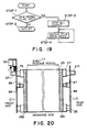
- Figure 19 is a flow chart of a film wrong or error program which is a part of the main program.
- step 11 the discrimination is made as to whether the film error flag is set or not. If not, the sequence proceeds to step 12, and the next step of the main sequential program is executed. If the film error flag is set in step 11, a step 13 operation is executed by which all of the outputs of the entire apparatus (the copying apparatus in this embodiment) are stopped. Then, a step 14 is executed to display the film error.
- the step 14 constitutes a permanent loop to prohibit execution of the main program.
- the endless film 25 of the fixing apparatus is first control to be shifted toward the front side, and when the film position sensor 86 detects the shift of the film to the front side, the solenoid 53 is actuated to shift the film toward the rear side. Similarly, the film shifted to the rear side is detected by the film position sensor 97. When the shift to the rear side is detected, the solenoid 53 is deenergized to shift the film toward the front side.
- the film 25 is always maintained in the range between the sensors 86 and 97, and simultaneously, when the sensors 85 and 96 disposed outside the sensors 86 and 97 detects the event that the film is erroneously shifted due to malfunction of the solenoid 53 or the spring 79, the operation of the apparatus is stopped, thus preventing the damage of the film, and also, the error in the fixing apparatus is displayed to notify it to the operator.
- the film error program shown in Figure 19 each time the image forming operation is completed, the film error program is executed upon the image forming operation completion, if the error is detected during the image forming operation; by which the operation of the apparatus can be stopped, and the next image forming operation can be disabled.
- the film 25 error detecting position is disposed more inside the position where the film 25 is actually damaged by a distance longer than a distance through which the film 25 moves in the time period required for one image formation.
- the sensors 86, 97, 85 and 96 are of transparent type, but other sensors of microswitch type or a reflection type photosensor may be similarly used.
- Figure 21 is a control flow chart for the embodiment of Figure 20.
- the control program of this embodiment is accessed by the main sequential program and is executed.
- the discrimination is made as to whether the motor 67 is actuated or not, at step 20.
- the step 29 is executed by which the solenoid 53 is deenergized, and rear side flag is reset, and then the operation proceeds to the outlet at step 24.
- the motor 67 is actuated in step 20
- the operation of step 21 is executed in which the shift control program is performed.
- the discrimination is made as to whether the film is going to shift rearwardly or frontwardly.
- the rear side flag is checked.
- step 22 is executed by which the discrimination is made as to whether the sensor 86 is actuated or not. If so, that is, if the film 25 shifts to the sensor 86, the operation of step 23 is performed.
- step 23 a timer 1 having a timer period of T1 sec, is started, and the solenoid 53 is energized to control to shift the film rearwardly. Then, the rear side flag is set, and the operation advances to the outlet at step 24, and returned to the main program. If the sensor 86 is not actuated at step 22, the operation of step 25 is carried out.
- step 25 the discrimination is made as to whether or not a timer period T2 sec of a timer 2 as passed or not. If not, the operation advances to step 24 (outlet), if so, step 26 is executed, wherein the discrimination is made as to whether the sensor 97 is actuated or not. If not, the operation skips to the step 24 (outlet). If so, that is, the rear side sensor 97 detects the film 25 even if the control is effected to shift it frontwardly and even if the predetermined period T2 sec as passed, operation of step 32 is executed to set the film error flag, and the operation is advanced to the outlet at step 24 through a step 29 and then, is returned to the main program.
- step 27 the operation of step 27 is executed.
- the discrimination is made as to whether or not the sensor 97 is actuated. If so, that is, if the film 25 moves to the position of the rear sensor 97, the operation of a step 28 is performed.
- a timer in having a timer period of T2 sec is started, and an operation in step 29 is executed in which the solenoid 53 is deenergized to displace the film 25 frontwardly, and the rear side flag is reset to zero. Then, the operation advances to the outlet at step 24.
- step 30 the operation of step 30 is executed, wherein the discrimination is made as to whether the timer period T1 sec of the timer 1 has passed or not. If not, the operation skips to the outlet (step 24). If so, the operation of step 31 is executed in which the discrimination is made as to whether or not the sensor 86 is actuated. If not, the sequence proceeds to the step 24 (outlet). If so, that is, even if the control is such as to displace the film 25 rearwardly, the front sensor 86 detects the film even if the predetermined timer period T1 has passed, the operation of step 32 is executed, and the film error flag is set. The operation proceeds to the outlet (step 24) through the step 29, and is returned to the main program.
- the endless film 25 of the fixing apparatus of this embodiment is controlled to be displaced toward the front, and when the film position sensor 86 detects the event that the film 25 is shifted to the front side, the solenoid 53 is energized, so that the control is switched to the control for shifting the film 25 to the rear side.
- the timer 1 for measuring the predetermined timer period T1 is started.
- the film 25 is considered to displace toward the rear side.
- the chip is made as to whether the sensor 86 is actuated or not. If the film 25 is not moved to the sensor 86, the film error is detected.
- the solenoid 53 is deenergized to displace the film 25 toward the front side, and simultaneously, the timer 2 for measuring the timer period T1 is started. By this, the film moves toward the front side.
- the check is made as to whether the sensor 97 is actuated or not. If the film 25 is not moved to the front side to the sensor 97, the film error is discriminated. If the fixing apparatus is in order, the film 25 is controlled in its position by the sensors 86 and 97.
- Each of those periods is longer than the time required after the front side sensor 86 or the rear side sensor 97 detects the film 25 and the shift control is effected in the opposite direction, and before the film is not detected by the sensor.
- Each of the time period is shorter than the period for the film to move to such a position where the film is damaged by the side plate or the like, after the sensor 86 or 97 detects the film, when the control is not possible.
- step 40 in Figure 22 the discrimination is made as to whether or not the motor is actuated. If not, the operation of step 29 of Figure 23 is effected, wherein the solenoid 53 is deactuated, and the rear side flag is reset, and thereafter, the operation proceeds to the outlet at step 24, similarly to the foregoing embodiment. If the motor is actuated at step 40, the operation of step 41 is executed, wherein the measurement completion flag is checked. If the measurement completion flag is zero, the operation of step 42 is executed.
- step 42 the discrimination is made as to whether the film 25 is going to move to the front or to the rear.
- the rear side flag is checked. If the rear side flag is zero, that is, if the film 25 is going to shift to the front side, the step 43 is executed.
- step 43 the discrimination is made as to whether the sensor 86 is actuated or not. If not, the operation proceeds to step 24 (outlet) of Figure 23.
- the operation of step 44 is performed, wherein a second flag is checked. If the second flag is zero, that is, if the film 25 first comes to the front side sensor, the operation in step 45 is executed.
- step 45 the rear side measurement timer is start, and the second flag is set to 1.
- step 46 is executed by which the solenoid 53 is energized to shift now the film 45 to the rear side, and the rear flag is set to 1, and the operation proceeds to step 24 of Figure 23.
- step 48 operation is carried out.
- step 48 the discrimination is made as to the sensor 97 is actuated or not. If the film 25 does not reach the position of the sensor 97, the operation proceeds to the outlet at step 24 ( Figure 23). If the sensor 97 is actuated, that is, if the film 25 is displaced to the rear side, the operation of step 49 is performed.
- step 49 the front side measurement timer is started, and simultaneously therewith, the solenoid 53 is deenergized to displace now the film 25 toward the front side, and the rear side flag is reset to zero. Then, the rear side measurement timer is stopped, and the timer period is read and is written in the RAM in the microcomputer 66 at a predetermined address. Then, the operation proceeds to the step 24, outlet ( Figure 23).
- step 47 If the second flag is discriminated as being 1 in step 44, that is, if the film reaches the position of the sensor 86 for the second time after the film 25 first reaches the sensor 86, is displaced to the rear side sensor 97 by the control, and the control is switched to displace the film 25 back to the front side, the operation of step 47 is performed.
- the front side measurement timer is stopped, and the timer period is read.
- the timer period is the period required for the film 25 to displace from the sensor 97 position to the sensor 86 position toward the front side. Since the distance between the sensors 86 and 97 and the width of the film are known, the distance of the film movement toward the front per unit time is measured.
- the distance through which the film 25 moves per unit time toward the rear side is determined from the rear side measurement timer.
- the detecting timing of each of the sensors 86 and 97 can be calculated from the movement distance per unit time and the distance between the position where the sensor 86 or 97 detects the film 25 and the film displaces to such a position that it is not detected by the sensor after the opposite displacement control.
- the error detecting timing can be calculated from the position where the sensor 86 or 97 detects the film and a position where the film is damaged by the side plate or the like.
- the time periods which are longer than the period to the detection timings and shorter than the periods to the error detecting timing are calculated, and they are set in the timer 1 and the timer 2, respectively.
- the calculation program is constructed such that the timer periods T1 and T2 are the center between the detection timing and the error detecting timing. After the timer periods T1 and T2 are set, the measurement completion flag is set to 1, and the operation of step 46 is performed wherein the solenoid 53 is actuated by which the film 25 is shifted to the rear side. Then, the rear side flag is set to 1, and thereafter, the operation proceeds to the outlet at step 24 ( Figure 23).
- step 41 If the measurement completion flag is 1 in step 41, that is, after the moving periods to the front side and the rear side are measured, the timer periods T1 and T2 are calculated and are set, the operation of a step 21 ( Figure 23) is performed.
- the operation after the step 21 is the same as in Figure 21 embodiment, and thereafter, the description is omitted for simplicity.
- the timing of error detection can be selected most properly, and simultaneously, the assured shift control and assured film position error detection are possible without increasing very much the assembly precision of the driving roller 26, the follower roller 27, the heater 20 and the pressing roller 28.
- step 23 the operation of step 23 is carried out.
- the timer 1 for measuring a predetermined timer period T1 sec is started, and then, the solenoid 53 is energized to displace the film toward the rear side. Then, the rear side flag is set, and the operation proceeds to the outlet at the step 24, and is returned to the main program.
- the sensor 86 is not actuated in step 22, the operation advances to step 25, wherein the discrimination is made as to whether the timer period T2 of the timer 2 has passed or not. If not, the operation proceeds to the outlet at step 24.
- step 27 is executed in which the discrimination is made as to whether or not the sensor 97 is actuated. If so, that is, the film 25 has moved to the position of the rear side sensor 97, the operation of step 28 is executed.
- step 28 the timer 2 for measuring a predetermined timer period T2 sec is started, and step 29 is executed, by which the solenoid 53 is deenergized to shift the film 25 toward the front, and the rear side flag is reset to zero, and thereafter, the operation proceeds to the outlet at step 24. If the sensor 97 is not actuated at step 27, an operation of step 30 is performed.
- step 30 the discrimination is made as to whether the timer period T1 of the timer 1 has passed or not. If not, the operation proceeds to the outlet at step 24. If so, that is, if the film does not displace to the position of the rear side sensor 97 even if the predetermined period T1 sec has passed despite the control to the film 25 toward the rear side, the operation of step 32 is carried out, in which the film error flag is set, and the operation advances to the outlet at step 24 through the step 29 and is returned to the main program.
- the film 25 is controlled to move to the front upon motor rotation, and thereafter, when the film position sensor 86 detects the film 25 at the front side, the solenoid 53 is energized to displace the film 25 now to the rear side. Simultaneously, the timer 1 for measuring the predetermined period T1 sec is started. Next, the film 25 displaces toward the rear. If the rear side sensor 97 is not actuated even if the timer period T1 of the timer 1 passes, the film error is detected.
- the solenoid 53 is deenergized to displace the film 25 toward the front, and simultaneously, the timer 2 for measuring the predetermined timer period T2 is started. By this, the film 25 is displaced toward the front side. Similarly to the case of the movement toward the rear, the film error is detected if the front side sensor 86 is not actuated even if the timer period T2 elapses.
- the selection of the timer period T1 and T2 will be described. First, the period T1 is longer than the period required for the film 25 to shift from the front side sensor 86 position to the rear side sensor 97 position.
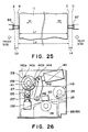
- Figure 25 shows the positional relations among the sensors and the film to meet the above requirements for the periods T1 and T2.
- the position indicated by a reference A is a front side limit position, and if the film 25 is displaced toward the front beyond this limit position, the film 25 is damaged.
- the position indicated by a reference B is a film detecting position by the front sensor 86.
- References C and D designate a film detecting position of the rear sensor 97, and a rear side limit position.
- the shift control of the endless film and the film error detection are possible, and simultaneously, the error detection is possible when the film is creased, with the result of the change in the width, or when the moving speed is changed.
- the bearing 135 of the follower roller 27 is supported on a side plate 88 for sliding movement in substantially the vertical direction, and its rotatably supports an end of the follower roller 27.
- the other end of the follower roller 27 is rotatably supported in a bearing (not shown) mounted in another side plate 89.
- a cam 139 having a radius which is different depending on the angular position thereof is fixed for integral rotation.
- the bottom side radius of the cam 139 is the maximum.
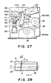
- the engaging pawl 140c and the lever pawl 144 are engaged, as shown in Figure 27, the bottom radius of the cam 139 is the minimum. The radius therebetween smoothly changes.
- the sensors 148 and 149 detects that the fixing film or a heat-resistive belt 25 is moved toward the rear or the front from the initial position through a predetermined distance.
- the output signals from the sensors 148 and 149 are amplified by a known control circuit, and in response to the signals, the solenoid 145 is energized for a predetermined period of time, and the cam 139 is maintained at a desired position.
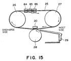
- Figure 29 shows the major part illustrating the heat-resistive belt 24, as seen from the sheet discharge side.
- the driving roller 27 rotates in the direction indicated by an arrow
- the end of the belt 25 wrapped at the point E moves in a direction perpendicular to the axis of the driving roller 26, and therefore, when the driving roller 26 rotates approximately through 180 degrees, it is shifted to the point E1.
- the belt 25 is shifted in the direction of an arrow J by a distance ⁇ d which is a distance between the point F and the point E1. Therefore, when the driving roller 26 continues to rotate in this state, the belt 25 gradually shifts in the direction J.
- the angular positions of the engaging pawls 140b and 140c are spaced by approximately 90 degrees. This is because the solenoid 145 energization period is made longer than the time period corresponding to the angular position of the engaging pawls 140b and 140c without using a cam position detecting switch or the like. Therefore, when the cam position detecting switch or the like is employed, the angular positions of the engaging pawls 140b and 140c may be different.
- the follower roller 27 is screwed.
- the heat-resistive belt 25 may be positively shifted by changing the distance between the rollers.
- the means for changing the roller position is not limited to the structure wherein the clutch 138 and a trigger solenoid are used. For example, the end of the shaft is directly moved by the solenoid.
- Sensors 148 and 149 are provided to energize or deenergize the solenoid 160 when the heat-resistive belt 25 is shifted by a predetermined amount.
- the sensor 148 is actuated to energize the solenoid 160 to shift the heat-resistive belt 25 back to the front side.
- the solenoid 160 is deenergized, by which the heat resistive belt 25 is shifted toward the rear side.
- the heat resistive belt 25 can be continuously moved toward the rear side and the front side within a predetermined range. Therefore, the heat resistive belt 25 is prevented from contacting the lateral edge of the transfer sheet P at the same position always.
- a rack 173 is formed at a side of the slider 170 opposite from the rear sensor 148, and a pinion gear 174 is meshed with the rack 173.
- the pinion gear 174 is rotated by an unshown actuator such as a small size motor or a plunger by the amount of several teeth at one time.
- an electric signal is applied to the actuator, upon which the pinion gear 174 rotates in the clockwise direction through the amount corresponding to its several teeth, by which the sensors 148 and 149 move in the direction M to the position indicated by the chain lines.
- the heat resistive belt 29 reciprocates within the range defined by the chain lines.
- Figure 31 shows such an embodiment.
- an eccentric cam 176 integrally rotatable with a gear 177 is contacted to a top end of a one way bearing 135 of the follower roller 27, so that the bearing 135 is moved upwardly and downwardly in response to 1/2 rotation of the eccentric cam 176.
- the gear 177 is rotated through 1/2 full turn by a known actuator for each of a predetermined number of rotations of the heat-resistive belt 25, so as to shift the belt 25, thus preventing the same positions of the belt 25 is contacted to the edges of the transfer sheet P.
- the belt shifting mechanism operates after a predetermined number of sheets are passed, and the belt 25 is shifted in the predetermined direction gradually without reciprocating the heat-resistive belt 25, and when the belt 25 reaches a limit position defined at one side, it is exchanged with a fresh belt.
- the belt is always moved in a direction perpendicular to the conveyance direction of the heat resistive belt, whereby the local wearing of the heat resistive belt can be prevented, so that it is substantially uniformly worn, and therefore the durability of the heat resistive belt is increased.
- the film is shifted during the fixing operation, but it is a very slow shifting, and therefore, it does not influence the image fixing operation.
Landscapes
- Physics & Mathematics (AREA)
- General Physics & Mathematics (AREA)
- Fixing For Electrophotography (AREA)
Applications Claiming Priority (10)
| Application Number | Priority Date | Filing Date | Title |
|---|---|---|---|
| JP159721/88U | 1988-12-08 | ||
| JP1988159721U JP2557780Y2 (ja) | 1988-12-08 | 1988-12-08 | 定着装置 |
| JP63313278A JPH087507B2 (ja) | 1988-12-12 | 1988-12-12 | 画像加熱定着装置 |
| JP313275/88 | 1988-12-12 | ||
| JP313278/88 | 1988-12-12 | ||
| JP63313275A JPH087506B2 (ja) | 1988-12-12 | 1988-12-12 | 画像加熱定着装置 |
| JP325561/88 | 1988-12-22 | ||
| JP63325561A JPH02168289A (ja) | 1988-12-22 | 1988-12-22 | 画像形成装置 |
| JP8037689A JPH0778658B2 (ja) | 1989-03-31 | 1989-03-31 | 加熱定着装置 |
| JP80376/89 | 1989-03-31 |
Publications (3)
| Publication Number | Publication Date |
|---|---|
| EP0372558A2 true EP0372558A2 (fr) | 1990-06-13 |
| EP0372558A3 EP0372558A3 (fr) | 1991-07-17 |
| EP0372558B1 EP0372558B1 (fr) | 1994-07-13 |
Family
ID=27524860
Family Applications (1)
| Application Number | Title | Priority Date | Filing Date |
|---|---|---|---|
| EP89122594A Expired - Lifetime EP0372558B1 (fr) | 1988-12-08 | 1989-12-07 | Appareil de fixage d'une image |
Country Status (4)
| Country | Link |
|---|---|
| US (1) | US5027160A (fr) |
| EP (1) | EP0372558B1 (fr) |
| KR (1) | KR940005135B1 (fr) |
| DE (1) | DE68916763T2 (fr) |
Cited By (7)
| Publication number | Priority date | Publication date | Assignee | Title |
|---|---|---|---|---|
| EP0411588A3 (en) * | 1989-08-01 | 1991-07-10 | Canon Kabushiki Kaisha | An image fixing apparatus |
| FR2656934A1 (fr) * | 1990-01-11 | 1991-07-12 | Canon Kk | Dispositif de commande de deplacement lateral pour une bande sans fin et appareil de fixage d'images l'utilisant. |
| EP0437203A3 (en) * | 1990-01-11 | 1992-10-21 | Canon Kabushiki Kaisha | Lateral shift control for endless belt and fixing apparatus using same |
| EP0519454A3 (en) * | 1991-06-20 | 1993-09-29 | Canon Kabushiki Kaisha | Lateral shift preventing mechanism for endless belt |
| US5293537A (en) * | 1991-01-10 | 1994-03-08 | Delphax Systems | Image transport fusing system |
| US8331827B2 (en) | 2008-07-16 | 2012-12-11 | Konica Minolta Business Technologies, Inc. | Image forming apparatus to control belt position |
| EP3291020A3 (fr) * | 2016-09-02 | 2018-06-06 | Toshiba TEC Kabushiki Kaisha | Dispositif de fixation |
Families Citing this family (47)
| Publication number | Priority date | Publication date | Assignee | Title |
|---|---|---|---|---|
| US5171969A (en) * | 1989-10-30 | 1992-12-15 | Canon Kabushiki Kaisha | Movable film fixing device with heater control responsive to selected sheet size |
| US5084738A (en) * | 1989-10-31 | 1992-01-28 | Canon Kabushiki Kaisha | Fixing apparatus |
| JPH0810379B2 (ja) * | 1989-10-31 | 1996-01-31 | キヤノン株式会社 | 定着装置 |
| JP2789753B2 (ja) * | 1990-01-09 | 1998-08-20 | キヤノン株式会社 | 定着装置 |
| JPH03233586A (ja) * | 1990-02-09 | 1991-10-17 | Canon Inc | 定着装置 |
| EP0443806B1 (fr) * | 1990-02-20 | 1996-07-31 | Canon Kabushiki Kaisha | Appareil de formation d'image avec détecteur d'erreur pour les moyens de fixage |
| JP2911525B2 (ja) * | 1990-02-20 | 1999-06-23 | キヤノン株式会社 | 加熱装置 |
| JP2821226B2 (ja) * | 1990-03-13 | 1998-11-05 | キヤノン株式会社 | 加熱装置 |
| US5148226A (en) * | 1990-06-11 | 1992-09-15 | Canon Kabushiki Kaisha | Heating apparatus using endless film |
| EP0461595B1 (fr) * | 1990-06-11 | 1996-03-13 | Canon Kabushiki Kaisha | Appareil de chauffage avec film sans fin |
| US5291256A (en) * | 1990-11-02 | 1994-03-01 | Canon Kabushiki Kaisha | Image forming apparatus having opening mechanism for jam clearance |
| US5210579A (en) * | 1990-11-30 | 1993-05-11 | Canon Kabushiki Kaisha | Image fixing apparatus having a parting resin layer for reducing frictional resistance of the film through which the image is heated |
| US5300998A (en) * | 1990-12-18 | 1994-04-05 | Canon Kabushiki Kaisha | Heating apparatus having a movable film protection member and image forming apparatus using same |
| JP2941962B2 (ja) * | 1991-01-08 | 1999-08-30 | キヤノン株式会社 | 定着装置 |
| US5196895A (en) * | 1991-02-15 | 1993-03-23 | Canon Kabushiki Kaisha | Heating apparatus using endless film |
| US5257078A (en) * | 1991-07-19 | 1993-10-26 | Canon Kabushiki Kaisha | Image heating apparatus regulating shift of endless fixing film |
| US5305066A (en) * | 1991-08-06 | 1994-04-19 | Canon Kabushiki Kaisha | Image heating device employing endless belt |
| JPH05338843A (ja) * | 1992-06-05 | 1993-12-21 | Canon Inc | 定着装置 |
| JPH05346746A (ja) * | 1992-06-16 | 1993-12-27 | Nec Niigata Ltd | 画像形成装置の定着装置 |
| JP3124375B2 (ja) * | 1992-06-16 | 2001-01-15 | キヤノン株式会社 | 加熱装置 |
| US5266970A (en) * | 1992-08-05 | 1993-11-30 | Eastman Kodak Company | Hot bar fuser |
| JP3234660B2 (ja) * | 1992-12-04 | 2001-12-04 | キヤノン株式会社 | 画像形成装置 |
| US6141525A (en) * | 1995-04-28 | 2000-10-31 | Canon Kabushiki Kaisha | Image forming apparatus having correction device for lateral misalignment |
| JP3180620B2 (ja) * | 1995-06-06 | 2001-06-25 | ミノルタ株式会社 | 定着ベルト方式の加熱定着装置 |
| JPH08339133A (ja) * | 1995-06-12 | 1996-12-24 | Minolta Co Ltd | 定着装置 |
| US6246858B1 (en) * | 1999-08-02 | 2001-06-12 | Xerox Corporation | Electrostatographic reproduction machine having a fusing belt position changing mechanism |
| US6643490B2 (en) * | 2001-12-12 | 2003-11-04 | Hewlett-Packard Development Company, Lp. | System for providing variable fusing energy to print media |
| EP1378802B1 (fr) | 2002-06-11 | 2015-08-12 | Canon Kabushiki Kaisha | Bande de fixage et son usage dans l'assemblage de fixage par chaleur d'une image |
| JP4194536B2 (ja) * | 2004-06-23 | 2008-12-10 | キヤノン株式会社 | 画像処理装置 |
| JP4630652B2 (ja) * | 2004-12-10 | 2011-02-09 | キヤノン株式会社 | 定着装置及び画像形成装置 |
| JP5031213B2 (ja) * | 2005-09-13 | 2012-09-19 | キヤノン株式会社 | 画像加熱装置、及び画像形成装置 |
| US20070090726A1 (en) * | 2005-10-24 | 2007-04-26 | Morris Grant A | Piezoelectric fan |
| US20070297081A1 (en) * | 2006-06-27 | 2007-12-27 | Seagate Technology Llc | Magnetic device for current assisted magnetic recording |
| US7430393B2 (en) * | 2006-07-03 | 2008-09-30 | Canon Kabushiki Kaisha | Belt feeding device and image heating device |
| JP4656667B2 (ja) * | 2006-12-12 | 2011-03-23 | キヤノン株式会社 | ベルト搬送装置およびトナー像加熱装置 |
| JP4988423B2 (ja) * | 2007-04-27 | 2012-08-01 | 株式会社リコー | ベルト装置及び画像形成装置 |
| JP2010085644A (ja) * | 2008-09-30 | 2010-04-15 | Canon Inc | 画像形成装置 |
| US8081915B2 (en) * | 2010-01-25 | 2011-12-20 | Xerox Corporation | Apparatus and method for controlling the change of direction of a fusing belt in a printing apparatus |
| US8078092B2 (en) * | 2010-01-25 | 2011-12-13 | Xerox Corporation | Apparatus and method for controlling the axial rate of movement of a fusing belt in a printing apparatus |
| JP5713690B2 (ja) | 2011-01-13 | 2015-05-07 | キヤノン株式会社 | シート搬送装置及び画像形成装置 |
| JP5847534B2 (ja) | 2011-10-21 | 2016-01-27 | キヤノン株式会社 | シート搬送装置、プリント装置およびジャム処理方法 |
| US9280101B2 (en) | 2013-02-18 | 2016-03-08 | Canon Kabushiki Kaisha | Image forming apparatus with lower and upper guide members |
| US11803139B2 (en) | 2013-02-18 | 2023-10-31 | Canon Kabushiki Kaisha | Image forming apparatus |
| US9513583B2 (en) * | 2013-07-30 | 2016-12-06 | Canon Kabushiki Kaisha | Fixing device for suppressing reduced durability of a flexible rotary member |
| JP6393084B2 (ja) | 2014-06-04 | 2018-09-19 | キヤノン株式会社 | 記録装置及びその制御方法、プログラム、記憶媒体 |
| JP7661158B2 (ja) * | 2021-07-13 | 2025-04-14 | キヤノン株式会社 | 画像形成装置 |
| JP2025136988A (ja) * | 2024-03-08 | 2025-09-19 | キヤノン株式会社 | 定着装置 |
Family Cites Families (7)
| Publication number | Priority date | Publication date | Assignee | Title |
|---|---|---|---|---|
| US3578797A (en) * | 1969-09-26 | 1971-05-18 | Eastman Kodak Co | Fusing method and apparatus |
| US3811828A (en) * | 1970-10-29 | 1974-05-21 | Ricoh Kk | Process and device for heating and fixing an image upon a recording medium |
| US3810735A (en) * | 1972-12-26 | 1974-05-14 | Xerox Corp | Heat fixing apparatus for fusible material |
| IT1212977B (it) * | 1983-02-10 | 1989-12-07 | Olivetti & Co Spa | Macchina copiatrice elettrofotogra fica |
| US4780742A (en) * | 1984-07-30 | 1988-10-25 | Canon Kabushiki Kaisha | Image quality improving process and apparatus and sheet usable therewith |
| US4565439A (en) * | 1984-10-31 | 1986-01-21 | Xerox Corporation | Low mass heat and pressure fuser |
| EP0295901B1 (fr) * | 1987-06-16 | 1995-12-20 | Canon Kabushiki Kaisha | Appareil de fixage d'images |
-
1989
- 1989-12-05 US US07/446,449 patent/US5027160A/en not_active Expired - Lifetime
- 1989-12-07 DE DE68916763T patent/DE68916763T2/de not_active Expired - Fee Related
- 1989-12-07 EP EP89122594A patent/EP0372558B1/fr not_active Expired - Lifetime
- 1989-12-08 KR KR1019890018163A patent/KR940005135B1/ko not_active Expired - Fee Related
Cited By (9)
| Publication number | Priority date | Publication date | Assignee | Title |
|---|---|---|---|---|
| EP0411588A3 (en) * | 1989-08-01 | 1991-07-10 | Canon Kabushiki Kaisha | An image fixing apparatus |
| US5235395A (en) * | 1989-08-01 | 1993-08-10 | Canon Kabushiki Kaisha | Image fixing apparatus |
| FR2656934A1 (fr) * | 1990-01-11 | 1991-07-12 | Canon Kk | Dispositif de commande de deplacement lateral pour une bande sans fin et appareil de fixage d'images l'utilisant. |
| EP0437203A3 (en) * | 1990-01-11 | 1992-10-21 | Canon Kabushiki Kaisha | Lateral shift control for endless belt and fixing apparatus using same |
| US5293537A (en) * | 1991-01-10 | 1994-03-08 | Delphax Systems | Image transport fusing system |
| EP0519454A3 (en) * | 1991-06-20 | 1993-09-29 | Canon Kabushiki Kaisha | Lateral shift preventing mechanism for endless belt |
| US5343279A (en) * | 1991-06-20 | 1994-08-30 | Canon Kabushiki Kaisha | Lateral shift preventing mechanism for endless belt |
| US8331827B2 (en) | 2008-07-16 | 2012-12-11 | Konica Minolta Business Technologies, Inc. | Image forming apparatus to control belt position |
| EP3291020A3 (fr) * | 2016-09-02 | 2018-06-06 | Toshiba TEC Kabushiki Kaisha | Dispositif de fixation |
Also Published As
| Publication number | Publication date |
|---|---|
| EP0372558A3 (fr) | 1991-07-17 |
| KR900010495A (ko) | 1990-07-07 |
| EP0372558B1 (fr) | 1994-07-13 |
| KR940005135B1 (ko) | 1994-06-11 |
| US5027160A (en) | 1991-06-25 |
| DE68916763D1 (de) | 1994-08-18 |
| DE68916763T2 (de) | 1994-11-03 |
Similar Documents
| Publication | Publication Date | Title |
|---|---|---|
| US5027160A (en) | Image fixing apparatus with movable film and means for controlling film position | |
| US4998121A (en) | Image forming apparatus | |
| EP0363686B1 (fr) | Appareil de fixage d'images | |
| EP0437205B1 (fr) | Appareil de fixage d'images | |
| US5852763A (en) | Image heating apparatus | |
| EP0509527B1 (fr) | Système de formation d'images comprenant une alimentation électrique principale coupée en mode d'attente | |
| EP1191406B1 (fr) | Appareil de formation d'images et procédé | |
| EP0432687B1 (fr) | Appareil de fixage d'images | |
| KR100191042B1 (ko) | 정착 장치 및 이 장치를 구비하는 화상 형성 장치 | |
| EP0443806B1 (fr) | Appareil de formation d'image avec détecteur d'erreur pour les moyens de fixage | |
| US5266774A (en) | Set temperature changeable image fixing apparatus | |
| EP0668547B1 (fr) | Appareil de formation d'images et appareil de fixage d'une image | |
| EP0436955B1 (fr) | Appareil de fixage d'images dont la température de référence peut être changée | |
| EP0390090B1 (fr) | Appareil de fixage d'images | |
| US6704526B2 (en) | Image heating apparatus adapted for cleaning of speed detection mark | |
| US5171145A (en) | Image fixing apparatus for heat fixing a toner image through a film | |
| EP0369378B1 (fr) | Appareil de fixage d'images | |
| JPH03259173A (ja) | 定着装置 | |
| JP3094532B2 (ja) | 像加熱装置 | |
| JP3094533B2 (ja) | 像加熱装置 | |
| JPH02157886A (ja) | 定着装置 | |
| JPH0511656A (ja) | 画像形成装置 | |
| JPH0968882A (ja) | 定着装置 | |
| JPH06118824A (ja) | 加熱装置及び画像形成装置 | |
| JPH0540423A (ja) | 加熱装置 |
Legal Events
| Date | Code | Title | Description |
|---|---|---|---|
| PUAI | Public reference made under article 153(3) epc to a published international application that has entered the european phase |
Free format text: ORIGINAL CODE: 0009012 |
|
| 17P | Request for examination filed |
Effective date: 19891207 |
|
| AK | Designated contracting states |
Kind code of ref document: A2 Designated state(s): DE FR GB IT |
|
| PUAL | Search report despatched |
Free format text: ORIGINAL CODE: 0009013 |
|
| AK | Designated contracting states |
Kind code of ref document: A3 Designated state(s): DE FR GB IT |
|
| 17Q | First examination report despatched |
Effective date: 19921125 |
|
| GRAA | (expected) grant |
Free format text: ORIGINAL CODE: 0009210 |
|
| AK | Designated contracting states |
Kind code of ref document: B1 Designated state(s): DE FR GB IT |
|
| REF | Corresponds to: |
Ref document number: 68916763 Country of ref document: DE Date of ref document: 19940818 |
|
| ITF | It: translation for a ep patent filed | ||
| ET | Fr: translation filed | ||
| ITTA | It: last paid annual fee | ||
| PLBE | No opposition filed within time limit |
Free format text: ORIGINAL CODE: 0009261 |
|
| STAA | Information on the status of an ep patent application or granted ep patent |
Free format text: STATUS: NO OPPOSITION FILED WITHIN TIME LIMIT |
|
| 26N | No opposition filed | ||
| REG | Reference to a national code |
Ref country code: GB Ref legal event code: IF02 |
|
| PGFP | Annual fee paid to national office [announced via postgrant information from national office to epo] |
Ref country code: GB Payment date: 20071205 Year of fee payment: 19 Ref country code: FR Payment date: 20071210 Year of fee payment: 19 |
|
| PGFP | Annual fee paid to national office [announced via postgrant information from national office to epo] |
Ref country code: IT Payment date: 20071228 Year of fee payment: 19 Ref country code: DE Payment date: 20071129 Year of fee payment: 19 |
|
| GBPC | Gb: european patent ceased through non-payment of renewal fee |
Effective date: 20081207 |
|
| REG | Reference to a national code |
Ref country code: FR Ref legal event code: ST Effective date: 20090831 |
|
| PG25 | Lapsed in a contracting state [announced via postgrant information from national office to epo] |
Ref country code: DE Free format text: LAPSE BECAUSE OF NON-PAYMENT OF DUE FEES Effective date: 20090701 |
|
| PG25 | Lapsed in a contracting state [announced via postgrant information from national office to epo] |
Ref country code: GB Free format text: LAPSE BECAUSE OF NON-PAYMENT OF DUE FEES Effective date: 20081207 |
|
| PG25 | Lapsed in a contracting state [announced via postgrant information from national office to epo] |
Ref country code: FR Free format text: LAPSE BECAUSE OF NON-PAYMENT OF DUE FEES Effective date: 20081231 |
|
| PG25 | Lapsed in a contracting state [announced via postgrant information from national office to epo] |
Ref country code: IT Free format text: LAPSE BECAUSE OF NON-PAYMENT OF DUE FEES Effective date: 20081207 |