EP0372618B1 - Düsenwebmaschine mit verbesserter Schussfadenzufuhr - Google Patents
Düsenwebmaschine mit verbesserter Schussfadenzufuhr Download PDFInfo
- Publication number
- EP0372618B1 EP0372618B1 EP89202998A EP89202998A EP0372618B1 EP 0372618 B1 EP0372618 B1 EP 0372618B1 EP 89202998 A EP89202998 A EP 89202998A EP 89202998 A EP89202998 A EP 89202998A EP 0372618 B1 EP0372618 B1 EP 0372618B1
- Authority
- EP
- European Patent Office
- Prior art keywords
- thread
- weaving machine
- machine according
- weft
- airjet
- Prior art date
- Legal status (The legal status is an assumption and is not a legal conclusion. Google has not performed a legal analysis and makes no representation as to the accuracy of the status listed.)
- Expired - Lifetime
Links
- 238000009941 weaving Methods 0.000 title claims description 44
- 230000007246 mechanism Effects 0.000 claims description 38
- 238000001514 detection method Methods 0.000 claims description 22
- 230000000903 blocking effect Effects 0.000 claims description 13
- 230000011664 signaling Effects 0.000 claims description 8
- 238000004804 winding Methods 0.000 claims description 6
- 238000009825 accumulation Methods 0.000 claims 1
- 230000008439 repair process Effects 0.000 description 5
- 239000004744 fabric Substances 0.000 description 3
- 235000014676 Phragmites communis Nutrition 0.000 description 1
- 230000003213 activating effect Effects 0.000 description 1
- 239000003086 colorant Substances 0.000 description 1
- 230000002950 deficient Effects 0.000 description 1
- 238000010586 diagram Methods 0.000 description 1
Images


Classifications
-
- D—TEXTILES; PAPER
- D03—WEAVING
- D03D—WOVEN FABRICS; METHODS OF WEAVING; LOOMS
- D03D47/00—Looms in which bulk supply of weft does not pass through shed, e.g. shuttleless looms, gripper shuttle looms, dummy shuttle looms
- D03D47/34—Handling the weft between bulk storage and weft-inserting means
-
- B—PERFORMING OPERATIONS; TRANSPORTING
- B65—CONVEYING; PACKING; STORING; HANDLING THIN OR FILAMENTARY MATERIAL
- B65H—HANDLING THIN OR FILAMENTARY MATERIAL, e.g. SHEETS, WEBS, CABLES
- B65H54/00—Winding, coiling, or depositing filamentary material
- B65H54/86—Arrangements for taking-up waste material before or after winding or depositing
- B65H54/88—Arrangements for taking-up waste material before or after winding or depositing by means of pneumatic arrangements, e.g. suction guns
-
- B—PERFORMING OPERATIONS; TRANSPORTING
- B65—CONVEYING; PACKING; STORING; HANDLING THIN OR FILAMENTARY MATERIAL
- B65H—HANDLING THIN OR FILAMENTARY MATERIAL, e.g. SHEETS, WEBS, CABLES
- B65H63/00—Warning or safety devices, e.g. automatic fault detectors, stop-motions ; Quality control of the package
- B65H63/02—Warning or safety devices, e.g. automatic fault detectors, stop-motions ; Quality control of the package responsive to reduction in material tension, failure of supply, or breakage, of material
- B65H63/024—Warning or safety devices, e.g. automatic fault detectors, stop-motions ; Quality control of the package responsive to reduction in material tension, failure of supply, or breakage, of material responsive to breakage of materials
- B65H63/036—Warning or safety devices, e.g. automatic fault detectors, stop-motions ; Quality control of the package responsive to reduction in material tension, failure of supply, or breakage, of material responsive to breakage of materials characterised by the combination of the detecting or sensing elements with other devices, e.g. stopping devices for material advancing or winding mechanism
-
- B—PERFORMING OPERATIONS; TRANSPORTING
- B65—CONVEYING; PACKING; STORING; HANDLING THIN OR FILAMENTARY MATERIAL
- B65H—HANDLING THIN OR FILAMENTARY MATERIAL, e.g. SHEETS, WEBS, CABLES
- B65H2701/00—Handled material; Storage means
- B65H2701/30—Handled filamentary material
- B65H2701/31—Textiles threads or artificial strands of filaments
Definitions
- This invention concerns an airjet weaving machine with an improved supply for the weft threads.
- the supply for weft threads on an airjet weaving machine normally consists of several thread preparation mechanisms, each made up of at least one yarn package, a thread accumulator such as for example a prewinder device, a thread blocking mechanism in order to release suitable lengths of weft thread from the prewinder device, and a main nozzle.
- the main nozzle of the deactivated thread preparation mechanism however remains activated, normally at a low rate of flow, so that the length of weft thread between the thread blocking mechanism and the main nozzle remains taut. If this were not the case, said length of weft thread would fall out of the main nozzle and become entangled in the other weft threads.
- the weaver Whenever a thread preparation mechanism is placed on standby, the weaver must intervene in order to repair the defective supply channel. However, it may happen that the above-mentioned length of weft thread has to wait too long in a main nozzle.
- the main nozzle is normally mounted on the sley of the weaving machine, and thus carries out a back-and-forth movement, with the result that the length of weft thread extending into the main nozzle is heavily stressed and can break.
- weft thread breaks close to the thread accumulator, there is a great chance of the broken-off piece of thread becoming entangled with the other weft threads, and thus either being blown together with them into the shed via another main nozzle or blocking the other main nozzles. In the latter case a weaving machine stop occurs which can last relatively long, since the weaver is usually not on the place immediately.
- the invention aims to provide a solution to the above-mentioned disadvantages, by among other things ensuring that before waiting for a thread break to occur in the length of weft thread extending into the main nozzle, a signal is given to the weaver, followed after a certain time by a partly or fully automatic thread removal of said length of weft thread.
- the time interval thus provided enables the weaver to intervene quickly, while in the extreme case, namely at the end of the time interval, the removal of said length of weft thread prevents a weaving fault being able to occur as a result of a loose piece of thread being blown into the shed.
- the invention concerns an airjet weaving machine with a supply consisting of at least two thread preparation mechanisms, each made up of: at least one yarn package, a thread accumulator mechanism, a thread blocking device and a main nozzle; detection means to sense thread breaks, where said detection means operates on at least one of the weft threads and is mounted between the corresponding yarn package and the corresponding thread blocking device; a control unit connected to the detection means and the thread preparation mechanisms, such that when the detection means senses a thread break, said control unit deactivates the thread preparation mechanism in which the thread break has occurred and transfers its task to another thread preparation mechanism; characterized in that the supply further comprises a control device connected to the detection means and consisting of at least a time delay circuit which produces an output signal for further processing after a certain time from the moment that the detection means senses a thread break; and thread removal means connected to the time delay circuit, said thread removal means can be activated by the output signal and can remove at least the weft thread section extending into the main nozzle.
- the airjet weaving machine is preferably equipped with a signalling device which is activated as soon as the above-mentioned detection means senses a thread break.
- other thread detectors are located near to the main nozzles, in order to monitor the presence of the weft threads. Whenever a break occurs prematurely in the weft thread on a main nozzle on standby, so that a piece of thread escapes and gets into the shed, the corresponding thread detector - which does not detect a thread any more - gives a signal, with the result that the main drive of the weaving machine is immediately shut down.
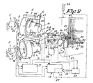
- Fig. 1 shows an airjet weaving machine, in which the supply 1 according to the invention is shown schematically.
- the supply 1 essentially consists of at least two thread preparation mechanisms 2 and 3, each composed of at least one yarn package 4, a thread accumulator mechanism such as a prewinder device 5, a thread blocking device 6 and a main nozzle 7.
- the supply 1 further consists of a detection means 8 for sensing thread breaks 9, where said means operates on at least one of the weft threads 10 and/or 11 of the respective yarn packages 4; a control unit 12 connected to the detection means 8 and to the thread preparation mechanisms 2 and 3, more specifically the prewinder device 5, such that when the detection means 8 senses a thread break 9, said control unit deactivates the thread preparation mechanism in which the thread break 9 has occurred, and transfers its task to other thread preparation mechanisms; a control device 13 connected to the detection means 8, consisting of at least a time delay circuit 14 which provides an output signal 15 for further processing a certain time after the detection means 8 has sensed a thread break 9; and thread removal means 16 connected to the time delay circuit 14 which can be activated by the output signal 15 and which can remove at least the weft thread section of the weft thread 10 in which a thread break 9 has occurred extending into the main nozzle 7.
- the prewinder devices 5 consist respectively of a fixed prewinder drum 17 and a rotating winding tube 18 which lays turns 19 on the prewinder drum 17.
- the thread blocking devices 6 each consist, in the known way, of a pin 20 which moves up and down, where said pin 20 operates on the corresponding prewinder drum 17 and is moved by means of a solenoid 21.
- the detection means 8 consists of thread break detectors 22 mounted in the paths of the weft threads 10 and 11, in particular between the yarn packages 4 and the respective thread blocking devices 6. The most suitable position is at the entrance to the winding tubes 18.
- main nozzles 7 are normally mounted on the sley 23, and carry out a back-and-forth movement.
- Auxiliary main nozzles 24 may or may not be placed in the paths of the weft threads 10 and 11.
- the control device 13 is connected via the time delay circuit 14 to said thread removal means 16 and possibly to the main drive 25 of the weaving machine and a signalling device 26, which consists for example of a number of lamps. There is also a direct connection 27 between the signalling device 26 and the control device 13.
- a thread removal device 16 mounted in the paths of the weft threads 10 and 11 makes it possible to draw the sections of weft thread extending into the main nozzles 7, for example the section 10A located between the main nozzle 7 and the corresponding auxiliary main nozzle 24, out of the respective main nozzles 7 and to grip them separately.
- Said thread removal devices 16 are controlled by a control unit 28, which in turn is controlled by the output signal 15 of the time delay circuit 14.
- Such thread removal devices 16 can for example be mounted at the entrances to the auxiliary main nozzle 24, as is shown in figure 2.
- the thread removal devices 16 consist for example of a body 29 with a thread guide channel 30, a holder 31 for storing a quantity of thread 32 and a nozzle 33, controlled by the control unit 28, which can blow the section of weft thread 10A into the holder 31.
- the holder 31 consists for example of a channel with one end 34 opening perpendicular to the thread guide channel 30, and with the other end 35 communicating with the environment and closed by a sieve-like element 36 which prevents the passage of thread but allows air to escape.
- the channel of the holder 31 is curved so that the section of weft thread 10A remains caught in the holder 31 after it has been blown into said holder 31.
- detectors 42 can be mounted at the output side of the thread preparation mechanisms 2 and 3. These detectors preferably work in conjunction with the thread guide tubes of the main nozzles 7, or are mounted just after the exits of the main nozzles 7. If said detectors 42 do not detect one of the weft threads 10 and/or 11, they supply a signal, with the result that the main drive 25 is shut down.
- the detectors 42 can either be connected directly to the main drive 25, as shown in fig. 2, or they can be connected indirectly to it, for example via the control device 13.
- the operation of the supply according to fig. 2 is now described for a thread break 9 which has occurred in the weft thread 10.
- the thread break detector 22 of the thread preparation mechanism 2 senses this thread break.
- the control unit 12 is activated, such that the thread preparation mechanism 2 is deactivated and its task taken over by the thread preparation mechanism 3.
- the drive of the winding tube 18 of the prewinder device 5 of the thread preparation mechanism 2 is stopped, while the corresponding pin 20 is kept in the closed position.
- the main nozzle 7 of the thread preparation mechanism 2 however remains activated at a low flow rate, such that the section of weft thread 10B between the main nozzle 7 and the corresponding thread blocking device 6 remains taut.
- the section of weft thread 10B will normally break off after a certain length of time, with the chance that it will either be woven in or become entangled in the other weft thread 11.
- the control device 13 is activated according to the present invention from the moment that the thread break 9 is detected, such that an output signal 15 is supplied by the time delay circuit 14 after a certain time.
- the control device 28 is activated by the output signal 15, with the result that the thread removal device 16 which operates on the thread 10 is activated, such that this thread, or at least the section 10A of it which extends into the corresponding main nozzle 7, is blown into the holder 31 by means of the nozzle 33, as shown in fig. 3. Since the quantity of thread 32 lodges in the curved holder 31, no more tension force is required in order to hold the weft thread in front of the thread removal device 16, and the piece of thread removed cannot form any more obstruction to subsequent weft threads 11 being inserted.
- a detector 43 in the auxiliary main nozzle 24 in order to determine whether the corresponding section of weft thread 10A between the auxiliary main nozzle 24 and the main nozzle 7 has been completely removed.
- This detector 43 can be connected to the control unit 28, such that whenever it does not detect a thread any more, the nozzle 33 of the corresponding thread removal device 16 is deactivated.
- a flashing lamp is activated on the signalling device 26 via the connection 27, so that the lamp goes slowly on and off.
- the lamp is activated continuously by means of the output signal 15.
- the lamp can for example flash progressively faster, according to the elapsed interval of the time delay.
- the time delay is preferably adjustable.
- the time delay to be set is preferably chosen by trial and error, by determining the period after which thread breaks normally occur. This will of course depend on the quality and the type of weft yarn used.
- the minimum time delay used for this purpose before activating the thread removal device 16 is the time necessary to switch from thread preparation mechanism 2 to thread preparation mechanism 3 after a signal has been given by the detector 22.
- the maximum time delay must not be greater than the period after which there is a real chance of the corresponding section of weft thread 10B breaking.
- a time interval is used which permits manual intervention on the part of the weaver before the automatic thread removal device 16 is activated. In that case, clearly the main nozzle 7 concerned is still threaded, so there is no need to rethread the main nozzle 7. The weaver only has to repair the thread break 9.
- rethreading the main nozzle 7 concerned does not necessarily have to be done via the thread preparation mechanism 2 in which the thread break 9 has occurred, but can also be done via another thread preparation mechanism which contains weft thread of the same type and also consists of a yarn package, a thread accumulator mechanism and a thread blocking device.
- the moment at which the other weft threads are inserted is taken into account. Care should be taken among other things to remove the section of weft thread 10A between the auxiliary main nozzle 24 and the main nozzle 7 at a moment when no weft thread is being inserted. This ensures that while the thread is being removed there is only a minimal chance of it becoming entangled with one of the other weft threads being inserted, or being blown simultaneously into the shed along with the other weft thread via another main nozzle, or blocking another main nozzle.
- the signal supplied by the control unit 12 to the solenoid 21 of the pin 20 can for example also be supplied to the control device 13, such that the output signal 15 is only supplied when no weft thread is being inserted.
- the main drive 25 of the weaving machine is shut down automatically.
- a second output signal 15 is supplied, in order to activate the thread removal device 16. Since thread removal is carried out during a machine stop, the above-mentioned problems cannot occur while thread removal is being carried out. Once the detector 43 does not sense a thread any more, the thread removal device 16 is deactivated and the weaving machine is started automatically once more.
- a suitable lamp on the signalling device 26 can of course be lit, so that the weaver is informed of each step of the cycle.
- the duration of the time delay is usually chosen so that it is only a fraction of the time after which the weakest weft threads could possibly break.
- the detectors 42 In order to be able to intervene in case of such a fault, use is preferably made of the above-mentioned detectors 42. Whenever an unexpected thread break of this type occurs prematurely, the main drive 25 is immediately shut down. The weaver must then repair the fault and restart the weaving machine. In such a case a separately recognizable signal can be given, so that the weaver first repairs this machine and restarts it, with the aim of having as few weaving machines down as possible in the weaving mill. When the thread removal device 16 is activated, the detectors 42 are deactivated.
- This invention enables a great number of weaving faults to be avoided, so obtaining a significantly better quality of cloth.
- the total down time of the weaving machine is kept to a minimum, so that within the given time interval, the weaver himself can choose at what moment to briefly shut down the weaving machine and carry out a repair.
- the detection means 8 can also consist of one of the winding detectors 44.
- auxiliary main nozzles 24 are not indispensable.
- the thread removal means 16 can also be mounted at other points in the paths of the weft threads 10 and 11.
Landscapes
- Engineering & Computer Science (AREA)
- Textile Engineering (AREA)
- Quality & Reliability (AREA)
- Looms (AREA)
Claims (16)
- Lufstrahlwebmaschine mit einer Zufuhr (1) für Schußfäden bestehend aus: mindestens zwei Fadenaufbereitungsvorrichtungen (2,3), jede davon bestehend aus mindestens einem Fadenpaket (4), einer Fadensammelvorrichtung (5), einem Fadensperrgerät (6) und einer Hauptdüse (7) ; Detektore (8) zur Festellung von Fadenbrüchen (9), wo besagter Detektor einwirkt auf mindestens einen der Schußfäden (10,11) und montiert ist zwischen den entsprechenden Fadenpaketen (4) und dem entsprechenden Fadensperrgerät (6): einer Steuereinheit (12) verbunden mit dem Detektor (8) und der Fadenaufbereitungsvorrichtung (2), in solcher Weise, daß falls der Detektor (8) einen Fadenbruch (9) ermittelt, die genannte Steuereinheit die Fadenaufbereitungsvorrichtung (2) in der der Fadenbruch (9) stattgefunden hat ausschaltet und seine Aufgabe einer anderen Fadenaufbereitungsvorrichtung (3) weiterleitet; dadurch gekennzeichnet, daß die Zufuhr (1) weiter umfaßt; ein Steuergerät (13) verbunden mit dem Detektor (8), bestehend aus mindestens einem Verzögerungskreis (14) der ein Ausgangssignal (15) liefert zur weiteren Verarbeitung an einem bestimmten Augenblick nachdem der Detektor (8) einen Fadenbruch (9) festgestellt hat; und einem Fadenentfernungsgerät (16) verbunden mit dem Verzögerungskreis (14), das genannte Fadenentfernungsgerät (16) kann betätigt werden von dem Ausgangssignal (15) und kann mindestens den Teil des Schußfadens (10A) entfernen das sich bis in die Hauptdüse (7) erstreckt.
- Luftstrahlwebmaschine nach Anspruch 1, dadurch gekennzeichnet, daß die Entfernung des obengenannten Schußfadenteils (10A) ausgeführt wird an dem Augenblick in dem kein Schußfaden eingeführt wird.
- Luftstrahlwebmaschine nach Anspruch 1 oder 2, dadurch gekennzeichnet, daß der Verzögerungskreis (14) verbunden ist mit einem Signalgerät (26) das mindestens arbeitet von dem Augenblick daß das obengenannte Ausgangssignal (15) geliefert wird.
- Luftstrahlwebmaschine nach Anspruch 1, dadurch gekennzeichnet, daß der Verzögerungskreis (14) verbunden ist mit dem Hauptantrieb (25) der Webmaschine sodaß nach einer ersten Verzögerung, ein Ausgangssignal (15) den Ergebnis hat, daß der Hauptantrieb (25) der Webmaschine angehalten wird, und daß der Verzögerungskreis (14) verbunden ist mit Fadenentfernungsgeräten (16), wo ein Ausgangssignal (15) den Ergebnis hat daß das Fadenentfernungsgerät (16) nach einer zweiten Verzögerung betätigt wird, sodaß nachdem der Teil des Schußfadens (10A) der sich bis in die Hauptdüse (7) erstreckt entfernt worden ist, das Fadenentfernungsgerät (16) ausgeschaltet wird und der Hauptantrieb (25) der Webmaschine wieder gestartet wird.
- Luftstrahlwebmaschine nach einem beliebigen der obengenannten Ansprüchen, dadurch gekennzeichnet, daß das Steuergerät (13) auch ein Signalgerät (26) umfaßt das betätigt wird mittels einer unmittelbaren Verbindung (27) sobald der obengenannte Detektor (8) einen Fadenbruch (9) festgestellt hat.
- Luftstrahlwebmaschine nach Anspruch 5, dadurch gekennzeichnet, daß sie ein Signalgerät (26) hat das verschiedene Signale liefern kann, die progressive betätigt werden können je nachdem die Zwischenzeit des Verzögerungskreises (14) abläuft.
- Luftstrahlwebmaschine nach einem beliebigen der obengenannten Ansprüche, dadurch gekennzeichnet, daß die Fadensammelvorrichtung (5) respektive besteht aus einem Vorwickeltrommel (17) und einem Wickelrohr (18), wo der Detektor (8) besteht aus einem Fadenbruchdetektor (22) angeordnet auf dem Eingang des Wickelrohrs (18).
- Luftstrahlwebmaschine nach einem beliebigen der obengenannten Ansprüche, dadurch gekennzeichnet, daß die Detektore (42) angeordnet sind nahe dem Ausgangsende der Fadenaufbereitungsvorrichtungen (2,3), wo die genannten Detektore wirken können an den Schußfäden (10,11) und unmittelbar, oder nicht, verbunden sein können mit dem Hauptantrieb (25) der Webmaschine, sodaß falls die Abwesenheit eines Schußfadens (10,11) festgestellt wird ehe die Fadenentfernungsgeräte (16) betätigt worden sind, der Hauptantrieb (25) der Webmaschine ausgeschaltet wird.
- Luftstrahlwebmaschine nach Anspruch 8, dadurch gekennzeichnet, daß die obengenannten Detektore (42) an den Ausgängen der Hauptdüsen (7) angeordnet sind.
- Luftstrahlwebmaschine nach einem beliebigen der obengenannten Ansprüche, dadurch gekennzeichnet, daß die Fadenentfernungsgeräte (16) angeordnet sind zwischen den Fadenpaketen (4) und ihren respektiven Hauptdüsen (7).
- Luftstrahlwebmaschine nach Anspruch 10, dadurch gekennzeichnet, daß in jedem der Läufe der Schußfäden (10,11) eine Hilfshauptdüse (24) angeordnet worden ist und daß die Fadenentfernungsgeräte (16) montiert worden sind an den Eingängen der respektiven Hilfshauptdüsen (24).
- Luftstrahlwebmaschine nach Anspruch 10 oder 11, dadurch gekennzeichnet, daß das Fadenentfernungsgerät (16) aus einem Hauptteil (29) besteht ausgestattet mit einem Fadenführungsrohr (30), einer rohrförmigen Halterung (31) und einer Düse (33) die einen Faden aus dem Fadenführungsrohr (30) in die Halterung (31) blasen kann.
- Luftstrahlwebmaschine nach Anspruch 12, dadurch gekennzeichnet, daß die Halterung (31) besteht aus einem Rohr mit einem Ende (34) senkrecht geöffnet in das Fadenführungsrohr (30) und mit dem anderen Ende (35) öffnend ins Freie.
- Luftstrahlwebmaschine nach Anspruch 13, dadurch gekennzeichnet, daß die Halterung (31) abgeschlossen ist von einer siebähnlichen Vorrichtung (36) am Ende (35) öffnend ins Freie.
- Luftstrahlwebmaschine nach Anspruch 12, 13 oder 14, dadurch gekennzeichnet, daß die Halterung (31) aus einem gekrümmten Rohr besteht.
- Luftstrahlwebmaschine nach einem beliebigen der obengenannten Ansprüche, dadurch gekennzeichnet, daß sie ausgestattet ist mit Detektoren (43) die die Anwesenheit von Schußfaden feststellen zwischen den Fadenentfernungsgeräten (16) und den Hauptdüsen (7) für die respektiven Schußfäden (10,11) und die die entsprechenden Fadenentfernungsgeräte (16) ausschalten wenn sie keinen Faden mehr feststellen.
Applications Claiming Priority (2)
| Application Number | Priority Date | Filing Date | Title |
|---|---|---|---|
| BE8801361 | 1988-12-05 | ||
| BE8801361A BE1001919A3 (nl) | 1988-12-05 | 1988-12-05 | Luchtweefmachine, met een verbeterde voeding voor de inslagdraden. |
Publications (2)
| Publication Number | Publication Date |
|---|---|
| EP0372618A1 EP0372618A1 (de) | 1990-06-13 |
| EP0372618B1 true EP0372618B1 (de) | 1993-01-27 |
Family
ID=3883754
Family Applications (1)
| Application Number | Title | Priority Date | Filing Date |
|---|---|---|---|
| EP89202998A Expired - Lifetime EP0372618B1 (de) | 1988-12-05 | 1989-11-27 | Düsenwebmaschine mit verbesserter Schussfadenzufuhr |
Country Status (4)
| Country | Link |
|---|---|
| US (1) | US4998567A (de) |
| EP (1) | EP0372618B1 (de) |
| BE (1) | BE1001919A3 (de) |
| DE (1) | DE68904639T2 (de) |
Families Citing this family (10)
| Publication number | Priority date | Publication date | Assignee | Title |
|---|---|---|---|---|
| IT1236993B (it) * | 1989-12-29 | 1993-05-12 | Roy Electrotex Spa | Alimentatore di trama per telai di tessitura a pinze e a proiettili |
| JP3036025B2 (ja) * | 1990-08-28 | 2000-04-24 | 株式会社豊田自動織機製作所 | ジェットルームにおける給糸処理装置 |
| JP2584991Y2 (ja) * | 1990-11-26 | 1998-11-11 | 株式会社豊田自動織機製作所 | ジェットルームにおける給糸処理装置 |
| BE1007850A3 (nl) * | 1993-12-01 | 1995-11-07 | Picanol Nv | Werkwijze en weefmachine met een voeding voor inslagdraden. |
| JP3157776B2 (ja) * | 1998-04-17 | 2001-04-16 | 津田駒工業株式会社 | 織機の起動方法 |
| JP4651817B2 (ja) * | 1998-10-09 | 2011-03-16 | バルマーク アクチエンゲゼルシヤフト | 糸を連続的に繰出すための方法 |
| TWI302903B (en) * | 2003-02-05 | 2008-11-11 | Saurer Gmbh & Co Kg | Yarn withdrawal device |
| DE102010035762A1 (de) * | 2010-08-28 | 2012-03-01 | Oerlikon Textile Gmbh & Co. Kg | Arbeitsstelle einer Spulmaschine und Verfahren zum Betreiben der Arbeitsstelle |
| JP6118572B2 (ja) * | 2013-02-05 | 2017-04-19 | 津田駒工業株式会社 | 流体噴射式織機における緯糸監視方法及び緯糸監視装置 |
| BE1027040B1 (nl) | 2019-02-08 | 2020-09-07 | Picanol Nv | Signaleringssysteem voor een weefmachine |
Family Cites Families (5)
| Publication number | Priority date | Publication date | Assignee | Title |
|---|---|---|---|---|
| EP0195469B2 (de) * | 1985-03-19 | 1993-12-29 | Picanol N.V. | Webmaschine mit Schussfadenspeicher |
| BE901969A (nl) * | 1985-03-19 | 1985-09-19 | Picanol Nv | Weefmachine met verbeterde voeding voor de inslagdraad. |
| JPS6342940A (ja) * | 1986-08-11 | 1988-02-24 | 津田駒工業株式会社 | よこ入れ制御装置 |
| NL8602724A (nl) * | 1986-10-29 | 1988-05-16 | Picanol Nv | Werkwijze en inrichting voor het herstellen van de draadtoevoer bij weefmachines bij een onderbreking tussen de bobijn en de draadvoorraad. |
| BE1000599A4 (nl) * | 1987-05-20 | 1989-02-14 | Picanol Nv | Werkwijze om te weven en weefmachine die deze werkwijze toepast. |
-
1988
- 1988-12-05 BE BE8801361A patent/BE1001919A3/nl not_active IP Right Cessation
-
1989
- 1989-11-27 EP EP89202998A patent/EP0372618B1/de not_active Expired - Lifetime
- 1989-11-27 DE DE8989202998T patent/DE68904639T2/de not_active Expired - Fee Related
- 1989-12-05 US US07/446,152 patent/US4998567A/en not_active Expired - Fee Related
Also Published As
| Publication number | Publication date |
|---|---|
| EP0372618A1 (de) | 1990-06-13 |
| DE68904639T2 (de) | 1993-06-03 |
| DE68904639D1 (de) | 1993-03-11 |
| US4998567A (en) | 1991-03-12 |
| BE1001919A3 (nl) | 1990-04-10 |
Similar Documents
| Publication | Publication Date | Title |
|---|---|---|
| EP0372618B1 (de) | Düsenwebmaschine mit verbesserter Schussfadenzufuhr | |
| BE1001819A3 (nl) | Inrichting en werkwijze voor de toevoer van inslagdraden bij weefmachines. | |
| US4924917A (en) | Weft thread break monitor and movement limiting device | |
| US4832091A (en) | Method and mechanism for repairing the weft supply on weaving machines in case of an interruption between the supply package and the weft accumulator | |
| US5050647A (en) | Damaged weft thread elimination in airjet weaving machines | |
| EP0292044B1 (de) | Webverfahren und Webmaschine, die dieses Verfahren anwendet | |
| EP0333262B1 (de) | Luftstrahlwebmaschine mit verbessertem Schussfadeneintrag | |
| EP0344848B1 (de) | Verfahren zum Einfädeln der Düsen mit einer richtigen Schlussfadenlänge und Webmaschine, die nach diesem Verfahren arbeitet | |
| EP1382727B1 (de) | Vorrichtung zum Vermeiden einer ungewollten Inbetriebnahme einer Webmaschine | |
| US4858658A (en) | Method and apparatus for repairing a broken weft thread in a loom | |
| EP0584738B1 (de) | Vorrichtung zum Entfernen von Schussfehlern in einer Webmaschine | |
| JP2969906B2 (ja) | ジェットルームにおける緯糸処理装置 | |
| JP3122251B2 (ja) | 不良糸除去方法 | |
| JP2519933B2 (ja) | 流体噴射式織機の給糸切れ糸排除装置 | |
| JPH04241143A (ja) | ジェットルームにおける緯糸処理装置 | |
| NL8602191A (nl) | Werkwijze voor het verwijderen van een foutieve inslagdraad bij een weefproces. | |
| JP3584568B2 (ja) | 織機における製織異常検出制御方法及び装置 | |
| JPH05156550A (ja) | レピヤ式織機における緯入れミス糸の除去方法およびこの方法を実施するための手段を有する織機 | |
| JP2754195B2 (ja) | 織機の給糸体の内外層排出方法と、それに使用する排出制御装置 | |
| JP3417010B2 (ja) | ジェットルームにおける緯入れミス糸の除去処理方法 | |
| JP2889765B2 (ja) | 織機の不良緯糸除去装置 | |
| JPH08311745A (ja) | ジェットルームの給糸装置 | |
| JP2002227062A (ja) | 織機の緯糸給糸方法 | |
| JPH01292147A (ja) | 無杼織機における緯糸処理方法 | |
| JPH08232140A (ja) | 織機における給糸体の緯糸排出方法 |
Legal Events
| Date | Code | Title | Description |
|---|---|---|---|
| PUAI | Public reference made under article 153(3) epc to a published international application that has entered the european phase |
Free format text: ORIGINAL CODE: 0009012 |
|
| AK | Designated contracting states |
Kind code of ref document: A1 Designated state(s): CH DE FR GB IT LI NL SE |
|
| 17P | Request for examination filed |
Effective date: 19900627 |
|
| 17Q | First examination report despatched |
Effective date: 19920424 |
|
| GRAA | (expected) grant |
Free format text: ORIGINAL CODE: 0009210 |
|
| AK | Designated contracting states |
Kind code of ref document: B1 Designated state(s): CH DE FR GB IT LI NL SE |
|
| PG25 | Lapsed in a contracting state [announced via postgrant information from national office to epo] |
Ref country code: FR Effective date: 19930127 Ref country code: NL Effective date: 19930127 Ref country code: SE Effective date: 19930127 |
|
| ITF | It: translation for a ep patent filed | ||
| REF | Corresponds to: |
Ref document number: 68904639 Country of ref document: DE Date of ref document: 19930311 |
|
| EN | Fr: translation not filed | ||
| NLV1 | Nl: lapsed or annulled due to failure to fulfill the requirements of art. 29p and 29m of the patents act | ||
| PGFP | Annual fee paid to national office [announced via postgrant information from national office to epo] |
Ref country code: GB Payment date: 19931126 Year of fee payment: 5 |
|
| PLBE | No opposition filed within time limit |
Free format text: ORIGINAL CODE: 0009261 |
|
| STAA | Information on the status of an ep patent application or granted ep patent |
Free format text: STATUS: NO OPPOSITION FILED WITHIN TIME LIMIT |
|
| 26N | No opposition filed | ||
| PG25 | Lapsed in a contracting state [announced via postgrant information from national office to epo] |
Ref country code: GB Effective date: 19941127 |
|
| GBPC | Gb: european patent ceased through non-payment of renewal fee |
Effective date: 19941127 |
|
| PGFP | Annual fee paid to national office [announced via postgrant information from national office to epo] |
Ref country code: DE Payment date: 20071203 Year of fee payment: 19 |
|
| PGFP | Annual fee paid to national office [announced via postgrant information from national office to epo] |
Ref country code: CH Payment date: 20071105 Year of fee payment: 19 Ref country code: IT Payment date: 20071026 Year of fee payment: 19 |
|
| REG | Reference to a national code |
Ref country code: CH Ref legal event code: PL |
|
| PG25 | Lapsed in a contracting state [announced via postgrant information from national office to epo] |
Ref country code: IT Free format text: LAPSE BECAUSE OF NON-PAYMENT OF DUE FEES Effective date: 20081127 |
|
| PG25 | Lapsed in a contracting state [announced via postgrant information from national office to epo] |
Ref country code: LI Free format text: LAPSE BECAUSE OF NON-PAYMENT OF DUE FEES Effective date: 20081130 Ref country code: DE Free format text: LAPSE BECAUSE OF NON-PAYMENT OF DUE FEES Effective date: 20090603 Ref country code: CH Free format text: LAPSE BECAUSE OF NON-PAYMENT OF DUE FEES Effective date: 20081130 |