EP0372736A2 - Contacts électriques - Google Patents
Contacts électriques Download PDFInfo
- Publication number
- EP0372736A2 EP0372736A2 EP89311919A EP89311919A EP0372736A2 EP 0372736 A2 EP0372736 A2 EP 0372736A2 EP 89311919 A EP89311919 A EP 89311919A EP 89311919 A EP89311919 A EP 89311919A EP 0372736 A2 EP0372736 A2 EP 0372736A2
- Authority
- EP
- European Patent Office
- Prior art keywords
- contact
- bent
- spring
- base portion
- side walls
- Prior art date
- Legal status (The legal status is an assumption and is not a legal conclusion. Google has not performed a legal analysis and makes no representation as to the accuracy of the status listed.)
- Granted
Links
Images

Classifications
-
- H—ELECTRICITY
- H01—ELECTRIC ELEMENTS
- H01R—ELECTRICALLY-CONDUCTIVE CONNECTIONS; STRUCTURAL ASSOCIATIONS OF A PLURALITY OF MUTUALLY-INSULATED ELECTRICAL CONNECTING ELEMENTS; COUPLING DEVICES; CURRENT COLLECTORS
- H01R13/00—Details of coupling devices of the kinds covered by groups H01R12/70 or H01R24/00 - H01R33/00
- H01R13/02—Contact members
- H01R13/10—Sockets for co-operation with pins or blades
- H01R13/11—Resilient sockets
-
- H—ELECTRICITY
- H01—ELECTRIC ELEMENTS
- H01R—ELECTRICALLY-CONDUCTIVE CONNECTIONS; STRUCTURAL ASSOCIATIONS OF A PLURALITY OF MUTUALLY-INSULATED ELECTRICAL CONNECTING ELEMENTS; COUPLING DEVICES; CURRENT COLLECTORS
- H01R43/00—Apparatus or processes specially adapted for manufacturing, assembling, maintaining, or repairing of line connectors or current collectors or for joining electric conductors
- H01R43/16—Apparatus or processes specially adapted for manufacturing, assembling, maintaining, or repairing of line connectors or current collectors or for joining electric conductors for manufacturing contact members, e.g. by punching and by bending
Definitions
- This invention relates generally to electrical contacts, and more particularly to electrical socket contacts.
- the invention relates to an electric socket contact to be connected with a pin contact, which can be manufactured from a strip or sheet of conductive material by means of press or forming machine.
- the contact spring section is surrounded by three sides, that is, the opposing side walls and an upper wall which can be formed by bending the strip.
- the back side of the contact spring section is not completely surrounded by the side walls, and therefore there are disadvantageous that the pin contact element is frequently inserted between the back of the contact spring section and a wall of the casing.
- the principal object of the present invention to provide a new and improved electrical socket contact having good structural integrity in which the contact spring section is completely surrounded by four side walls which are of a generally box-like configuration.
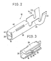
- an electrical socket contact of the present invention is illustrated generally at 10 attached to the first and second carrier strips 12 and 13.
- the contact 10 has undergone a first step of manufacture wherein the contact and associated carrier strips have been punched from a strip or sheet of conductive material, and wherein one of the ends to form a solderless electrical wire receiving portion 14 has been formed by providing a first break line 16 between the contact 10 and the first carrier strip 12.
- a second break line 20 is provided between a center contact arm which forms a base portion 18 of the contact 10 and the second carrier strip 13.
- the portions are respectively bent in opposed directions.
- the wire receiving portion 14 is formed by an insulation cover holding portion 22 and a wire contact portion 24.
- a first side flange which is parallel with the base portion 18 is bent to at an angle of 90° with the base portion 18 to form a first side wall 26 and a side portion which is parallel with the first side wall 26 is bent to at an angle of 90° with the first side wall 26 to form a spring base 28.
- Both ends of the spring base 28 are respectively bent in U-configuration to form an inner spring arm 30 and an outer spring arm 32.
- the outermost end of each of the inner and outer arms 30 and 32 is partially overlapped each other.
- the spring arm 32 is preferably provided with a protruded contact portion 34 and a nose portion 36.
- a second side flange which is opposite to the first side flange and parallel with the base portion 18 is bent at an angle of 90° to form a second side wall 38.
- a third side flange adjacent to the second side wall 38 is inwardly bent at an angle of 90° to form a top wall 40.
- An end of the top wall 40 is longitudinally toward the second carrier strip 13 and bent at an angle of 90° to form a front cover 42 of an opening into which the pin contact is inserted.
- the socket contact of the present invention can be formed by punched from a flat strip or sheet of conductive material.
- the socket contact may be formed by the base portion 18, the second and third side walls 26 and 38 which are respectively bent from each side of the base portion, the spring base 28 which is inwardly bent from the first side wall 26 and the inner and outer spring arms 30 and 32 which are respectively folded in U-like form from each end of the spring base portion 28 so as to overlap each other.
- the top wall 40 can enclose the spring base portion 28 from the outside thereof, and the spring arms 30 and 32 are completely surrounded by the base portion 18, the side walls 26 and 38 and the top wall 40. And also the inner and outer spring arms 30 and 32 are respectively protected by the front cover 42 from the outside of the opening into which the pin contact is inserted.
Landscapes
- Engineering & Computer Science (AREA)
- Manufacturing & Machinery (AREA)
- Manufacturing Of Electrical Connectors (AREA)
- Coupling Device And Connection With Printed Circuit (AREA)
- Connecting Device With Holders (AREA)
Applications Claiming Priority (2)
| Application Number | Priority Date | Filing Date | Title |
|---|---|---|---|
| JP157705/88U | 1988-12-05 | ||
| JP1988157705U JPH0429508Y2 (fr) | 1988-12-05 | 1988-12-05 |
Publications (3)
| Publication Number | Publication Date |
|---|---|
| EP0372736A2 true EP0372736A2 (fr) | 1990-06-13 |
| EP0372736A3 EP0372736A3 (en) | 1990-12-19 |
| EP0372736B1 EP0372736B1 (fr) | 1994-01-19 |
Family
ID=15655572
Family Applications (1)
| Application Number | Title | Priority Date | Filing Date |
|---|---|---|---|
| EP89311919A Expired - Lifetime EP0372736B1 (fr) | 1988-12-05 | 1989-11-16 | Contacts électriques |
Country Status (4)
| Country | Link |
|---|---|
| US (1) | US5112254A (fr) |
| EP (1) | EP0372736B1 (fr) |
| JP (1) | JPH0429508Y2 (fr) |
| DE (1) | DE68912540T2 (fr) |
Cited By (4)
| Publication number | Priority date | Publication date | Assignee | Title |
|---|---|---|---|---|
| EP0652606A1 (fr) * | 1993-11-08 | 1995-05-10 | Sumitomo Wiring Systems, Ltd. | Ensemble métallique de contact femelle pour connecteur |
| WO1996032757A1 (fr) * | 1995-04-13 | 1996-10-17 | The Whitaker Corporation | Contact a contrainte elevee |
| DE19619514A1 (de) * | 1996-05-14 | 1997-11-20 | Grote & Hartmann | Flachsteckkontakthülse |
| DE10103124B4 (de) * | 2000-01-24 | 2005-07-14 | Yazaki Corp. | Buchsenkontakt |
Families Citing this family (16)
| Publication number | Priority date | Publication date | Assignee | Title |
|---|---|---|---|---|
| JP2686199B2 (ja) * | 1992-01-28 | 1997-12-08 | 矢崎総業株式会社 | 雌型端子金具 |
| US5281175A (en) * | 1993-03-30 | 1994-01-25 | General Motors Corporation | Female electrical terminal |
| FR2711853B1 (fr) * | 1993-10-26 | 1995-12-01 | Cinch Connecteurs Sa | Organe de contact électrique femelle. |
| JPH07192793A (ja) * | 1993-12-28 | 1995-07-28 | Yazaki Corp | 端子構造 |
| GB9411287D0 (en) * | 1994-06-06 | 1994-07-27 | Amp Gmbh | High current receptacle terminal |
| US5897405A (en) * | 1997-05-29 | 1999-04-27 | Endo; Hiroshi | Electrical socket contact |
| JP2000311738A (ja) * | 1999-04-27 | 2000-11-07 | Yazaki Corp | 電気コンタクト |
| US6428366B1 (en) | 2000-11-03 | 2002-08-06 | Molex Incorporated | Electrical terminal socket and method of fabricating same |
| DE10161514B4 (de) * | 2000-12-18 | 2007-04-12 | Sumitomo Wiring Systems, Ltd., Yokkaichi | Anschlussbuchse |
| US8043130B2 (en) * | 2005-02-09 | 2011-10-25 | Fci Automotive Holding | Female electrical contact comprising spring contact plates |
| CN2800518Y (zh) * | 2005-05-20 | 2006-07-26 | 富士康(昆山)电脑接插件有限公司 | 电连接器端子 |
| US7387550B2 (en) * | 2005-07-21 | 2008-06-17 | Tyco Electronics Corporation | Dual beam receptacle contact |
| US7503813B1 (en) | 2007-05-17 | 2009-03-17 | Yazaki North America, Inc. | Electrical terminal with contoured contact element |
| JP2014160545A (ja) * | 2013-02-19 | 2014-09-04 | Sumitomo Wiring Syst Ltd | 雌端子金具 |
| JP2014170709A (ja) * | 2013-03-05 | 2014-09-18 | Sumitomo Wiring Syst Ltd | 雌端子金具 |
| CN215119312U (zh) * | 2021-05-25 | 2021-12-10 | 泰科电子(上海)有限公司 | 导电端子和连接器 |
Family Cites Families (8)
| Publication number | Priority date | Publication date | Assignee | Title |
|---|---|---|---|---|
| US1231417A (en) * | 1917-03-22 | 1917-06-26 | Arrow Electric Co | Attachment-plug receptacle. |
| US3299396A (en) * | 1964-11-27 | 1967-01-17 | Amp Inc | Contact terminal |
| US3836947A (en) * | 1973-02-23 | 1974-09-17 | Amp Inc | Electrical contact receptacle with helper spring |
| US4540233A (en) * | 1983-10-01 | 1985-09-10 | Tokai Electric Wire Company Limited | Female electrical terminal having improved contactor block structure |
| JPS6064584U (ja) * | 1983-10-07 | 1985-05-08 | 東洋ハーネス株式会社 | 雌形端子 |
| JPH0312229Y2 (fr) * | 1986-07-25 | 1991-03-22 | ||
| JPH0313987Y2 (fr) * | 1986-10-31 | 1991-03-28 | ||
| FR2613878B3 (fr) * | 1987-04-10 | 1989-10-20 | Francelco Sa | Contact electrique a organes de contact proteges |
-
1988
- 1988-12-05 JP JP1988157705U patent/JPH0429508Y2/ja not_active Expired
-
1989
- 1989-11-15 US US07/436,616 patent/US5112254A/en not_active Expired - Lifetime
- 1989-11-16 DE DE89311919T patent/DE68912540T2/de not_active Expired - Lifetime
- 1989-11-16 EP EP89311919A patent/EP0372736B1/fr not_active Expired - Lifetime
Cited By (5)
| Publication number | Priority date | Publication date | Assignee | Title |
|---|---|---|---|---|
| EP0652606A1 (fr) * | 1993-11-08 | 1995-05-10 | Sumitomo Wiring Systems, Ltd. | Ensemble métallique de contact femelle pour connecteur |
| US5503570A (en) * | 1993-11-08 | 1996-04-02 | Sumitomo Wiring Systems, Ltd. | Female terminal metal fixture for connector |
| WO1996032757A1 (fr) * | 1995-04-13 | 1996-10-17 | The Whitaker Corporation | Contact a contrainte elevee |
| DE19619514A1 (de) * | 1996-05-14 | 1997-11-20 | Grote & Hartmann | Flachsteckkontakthülse |
| DE10103124B4 (de) * | 2000-01-24 | 2005-07-14 | Yazaki Corp. | Buchsenkontakt |
Also Published As
| Publication number | Publication date |
|---|---|
| JPH0277876U (fr) | 1990-06-14 |
| DE68912540D1 (de) | 1994-03-03 |
| JPH0429508Y2 (fr) | 1992-07-16 |
| US5112254A (en) | 1992-05-12 |
| EP0372736B1 (fr) | 1994-01-19 |
| DE68912540T2 (de) | 1994-05-05 |
| EP0372736A3 (en) | 1990-12-19 |
Similar Documents
| Publication | Publication Date | Title |
|---|---|---|
| US5112254A (en) | Electrical contacts | |
| US5951336A (en) | Terminal fitting | |
| US5975964A (en) | Female terminal fitting | |
| US5588884A (en) | Stamped and formed contacts for a power connector | |
| US5207603A (en) | Dual thickness blade type electrical terminal | |
| US5897405A (en) | Electrical socket contact | |
| EP1162698B1 (fr) | Armature de borne femmelle | |
| JPS5924506B2 (ja) | 電気端子 | |
| JPH08507635A (ja) | 相互連結システム | |
| US5921821A (en) | Terminal fitting | |
| JP3062928B2 (ja) | コンタクト | |
| JP3115805B2 (ja) | 端子金具及び端子金具の製造方法 | |
| JPH07272773A (ja) | 圧接端子 | |
| EP0676827A2 (fr) | Contact électrique avec des surfaces de rétention secondaires améliorées | |
| US5554046A (en) | Solderless terminal | |
| JP3186021B2 (ja) | 同軸ケーブル用コネクタ及びその製造方法 | |
| EP1089383B1 (fr) | Organe de contact pour connecteurs et méthode de fabrication | |
| GB2043368A (en) | Insulation-displacement connector | |
| US4143936A (en) | Electrical contact | |
| JP2850109B2 (ja) | 接続用端子 | |
| EP0378337B1 (fr) | Pièce terminale pour haut-parleur à coinçage du fil | |
| US6080005A (en) | Terminal fitting | |
| US6296513B1 (en) | Electrical terminal for terminating at least two wires therein | |
| JPH0741100Y2 (ja) | ソケット・コンタクト | |
| JPH10270142A (ja) | 電気端子、それを含むコネクタ、及びコネクタの組立 方法 |
Legal Events
| Date | Code | Title | Description |
|---|---|---|---|
| PUAI | Public reference made under article 153(3) epc to a published international application that has entered the european phase |
Free format text: ORIGINAL CODE: 0009012 |
|
| AK | Designated contracting states |
Kind code of ref document: A2 Designated state(s): DE GB SE |
|
| PUAL | Search report despatched |
Free format text: ORIGINAL CODE: 0009013 |
|
| AK | Designated contracting states |
Kind code of ref document: A3 Designated state(s): DE GB SE |
|
| 17P | Request for examination filed |
Effective date: 19910204 |
|
| 17Q | First examination report despatched |
Effective date: 19930330 |
|
| GRAA | (expected) grant |
Free format text: ORIGINAL CODE: 0009210 |
|
| AK | Designated contracting states |
Kind code of ref document: B1 Designated state(s): DE GB SE |
|
| REF | Corresponds to: |
Ref document number: 68912540 Country of ref document: DE Date of ref document: 19940303 |
|
| PLBE | No opposition filed within time limit |
Free format text: ORIGINAL CODE: 0009261 |
|
| STAA | Information on the status of an ep patent application or granted ep patent |
Free format text: STATUS: NO OPPOSITION FILED WITHIN TIME LIMIT |
|
| 26N | No opposition filed | ||
| EAL | Se: european patent in force in sweden |
Ref document number: 89311919.8 |
|
| REG | Reference to a national code |
Ref country code: GB Ref legal event code: IF02 |
|
| PGFP | Annual fee paid to national office [announced via postgrant information from national office to epo] |
Ref country code: DE Payment date: 20081114 Year of fee payment: 20 |
|
| PGFP | Annual fee paid to national office [announced via postgrant information from national office to epo] |
Ref country code: SE Payment date: 20081107 Year of fee payment: 20 |
|
| PGFP | Annual fee paid to national office [announced via postgrant information from national office to epo] |
Ref country code: GB Payment date: 20081112 Year of fee payment: 20 |
|
| REG | Reference to a national code |
Ref country code: GB Ref legal event code: PE20 Expiry date: 20091115 |
|
| PG25 | Lapsed in a contracting state [announced via postgrant information from national office to epo] |
Ref country code: GB Free format text: LAPSE BECAUSE OF EXPIRATION OF PROTECTION Effective date: 20091115 |