EP0372785A2 - Apparat zum automatisierten Zusammenbau - Google Patents
Apparat zum automatisierten Zusammenbau Download PDFInfo
- Publication number
- EP0372785A2 EP0372785A2 EP89312321A EP89312321A EP0372785A2 EP 0372785 A2 EP0372785 A2 EP 0372785A2 EP 89312321 A EP89312321 A EP 89312321A EP 89312321 A EP89312321 A EP 89312321A EP 0372785 A2 EP0372785 A2 EP 0372785A2
- Authority
- EP
- European Patent Office
- Prior art keywords
- ferrule
- pair
- spring
- fixture
- ferrules
- Prior art date
- Legal status (The legal status is an assumption and is not a legal conclusion. Google has not performed a legal analysis and makes no representation as to the accuracy of the status listed.)
- Ceased
Links
- 125000006850 spacer group Chemical group 0.000 claims abstract description 53
- 239000003758 nuclear fuel Substances 0.000 claims abstract description 13
- 230000002093 peripheral effect Effects 0.000 claims description 8
- 230000001143 conditioned effect Effects 0.000 claims 1
- 238000000151 deposition Methods 0.000 claims 1
- 239000000446 fuel Substances 0.000 description 28
- 239000002826 coolant Substances 0.000 description 5
- 238000004519 manufacturing process Methods 0.000 description 5
- 238000010521 absorption reaction Methods 0.000 description 4
- 230000015572 biosynthetic process Effects 0.000 description 4
- 238000010276 construction Methods 0.000 description 3
- 239000011159 matrix material Substances 0.000 description 3
- 230000006835 compression Effects 0.000 description 2
- 238000007906 compression Methods 0.000 description 2
- 238000013461 design Methods 0.000 description 2
- 238000003780 insertion Methods 0.000 description 2
- 230000037431 insertion Effects 0.000 description 2
- 230000014759 maintenance of location Effects 0.000 description 2
- 239000000463 material Substances 0.000 description 2
- 230000003071 parasitic effect Effects 0.000 description 2
- 238000003466 welding Methods 0.000 description 2
- 229910001093 Zr alloy Inorganic materials 0.000 description 1
- WZECUPJJEIXUKY-UHFFFAOYSA-N [O-2].[O-2].[O-2].[U+6] Chemical compound [O-2].[O-2].[O-2].[U+6] WZECUPJJEIXUKY-UHFFFAOYSA-N 0.000 description 1
- 230000002159 abnormal effect Effects 0.000 description 1
- 230000006978 adaptation Effects 0.000 description 1
- SHZGCJCMOBCMKK-KGJVWPDLSA-N beta-L-fucose Chemical compound C[C@@H]1O[C@H](O)[C@@H](O)[C@H](O)[C@@H]1O SHZGCJCMOBCMKK-KGJVWPDLSA-N 0.000 description 1
- 238000006243 chemical reaction Methods 0.000 description 1
- 238000005253 cladding Methods 0.000 description 1
- 238000004891 communication Methods 0.000 description 1
- 230000003247 decreasing effect Effects 0.000 description 1
- 230000000694 effects Effects 0.000 description 1
- 230000004992 fission Effects 0.000 description 1
- 239000012530 fluid Substances 0.000 description 1
- 238000007373 indentation Methods 0.000 description 1
- 238000003754 machining Methods 0.000 description 1
- 238000012423 maintenance Methods 0.000 description 1
- 229910052751 metal Inorganic materials 0.000 description 1
- 239000002184 metal Substances 0.000 description 1
- 238000000034 method Methods 0.000 description 1
- 230000008450 motivation Effects 0.000 description 1
- 238000000926 separation method Methods 0.000 description 1
- 229910000439 uranium oxide Inorganic materials 0.000 description 1
- XLYOFNOQVPJJNP-UHFFFAOYSA-N water Substances O XLYOFNOQVPJJNP-UHFFFAOYSA-N 0.000 description 1
Images







Classifications
-
- G—PHYSICS
- G21—NUCLEAR PHYSICS; NUCLEAR ENGINEERING
- G21C—NUCLEAR REACTORS
- G21C3/00—Reactor fuel elements and their assemblies; Selection of substances for use as reactor fuel elements
- G21C3/30—Assemblies of a number of fuel elements in the form of a rigid unit
- G21C3/32—Bundles of parallel pin-, rod-, or tube-shaped fuel elements
- G21C3/34—Spacer grids
- G21C3/3424—Fabrication of spacer grids
-
- G—PHYSICS
- G21—NUCLEAR PHYSICS; NUCLEAR ENGINEERING
- G21C—NUCLEAR REACTORS
- G21C3/00—Reactor fuel elements and their assemblies; Selection of substances for use as reactor fuel elements
- G21C3/30—Assemblies of a number of fuel elements in the form of a rigid unit
- G21C3/32—Bundles of parallel pin-, rod-, or tube-shaped fuel elements
- G21C3/34—Spacer grids
- G21C3/344—Spacer grids formed of assembled tubular elements
-
- Y—GENERAL TAGGING OF NEW TECHNOLOGICAL DEVELOPMENTS; GENERAL TAGGING OF CROSS-SECTIONAL TECHNOLOGIES SPANNING OVER SEVERAL SECTIONS OF THE IPC; TECHNICAL SUBJECTS COVERED BY FORMER USPC CROSS-REFERENCE ART COLLECTIONS [XRACs] AND DIGESTS
- Y02—TECHNOLOGIES OR APPLICATIONS FOR MITIGATION OR ADAPTATION AGAINST CLIMATE CHANGE
- Y02E—REDUCTION OF GREENHOUSE GAS [GHG] EMISSIONS, RELATED TO ENERGY GENERATION, TRANSMISSION OR DISTRIBUTION
- Y02E30/00—Energy generation of nuclear origin
- Y02E30/30—Nuclear fission reactors
-
- Y—GENERAL TAGGING OF NEW TECHNOLOGICAL DEVELOPMENTS; GENERAL TAGGING OF CROSS-SECTIONAL TECHNOLOGIES SPANNING OVER SEVERAL SECTIONS OF THE IPC; TECHNICAL SUBJECTS COVERED BY FORMER USPC CROSS-REFERENCE ART COLLECTIONS [XRACs] AND DIGESTS
- Y10—TECHNICAL SUBJECTS COVERED BY FORMER USPC
- Y10T—TECHNICAL SUBJECTS COVERED BY FORMER US CLASSIFICATION
- Y10T29/00—Metal working
- Y10T29/53—Means to assemble or disassemble
- Y10T29/531—Nuclear device
-
- Y—GENERAL TAGGING OF NEW TECHNOLOGICAL DEVELOPMENTS; GENERAL TAGGING OF CROSS-SECTIONAL TECHNOLOGIES SPANNING OVER SEVERAL SECTIONS OF THE IPC; TECHNICAL SUBJECTS COVERED BY FORMER USPC CROSS-REFERENCE ART COLLECTIONS [XRACs] AND DIGESTS
- Y10—TECHNICAL SUBJECTS COVERED BY FORMER USPC
- Y10T—TECHNICAL SUBJECTS COVERED BY FORMER US CLASSIFICATION
- Y10T29/00—Metal working
- Y10T29/53—Means to assemble or disassemble
- Y10T29/534—Multiple station assembly or disassembly apparatus
- Y10T29/53404—Multiple station assembly or disassembly apparatus including turret-type conveyor
-
- Y—GENERAL TAGGING OF NEW TECHNOLOGICAL DEVELOPMENTS; GENERAL TAGGING OF CROSS-SECTIONAL TECHNOLOGIES SPANNING OVER SEVERAL SECTIONS OF THE IPC; TECHNICAL SUBJECTS COVERED BY FORMER USPC CROSS-REFERENCE ART COLLECTIONS [XRACs] AND DIGESTS
- Y10—TECHNICAL SUBJECTS COVERED BY FORMER USPC
- Y10T—TECHNICAL SUBJECTS COVERED BY FORMER US CLASSIFICATION
- Y10T29/00—Metal working
- Y10T29/53—Means to assemble or disassemble
- Y10T29/534—Multiple station assembly or disassembly apparatus
- Y10T29/53417—Means to fasten work parts together
- Y10T29/53426—Means to fasten work parts together by elastic joining
Definitions
- Nuclear power reactors are a well known source of energy.
- the nuclear fuel is comprised of elongated rods formed of sealed cladding tubes of suitable material, such as a zirconium alloy, containing uranium oxide and/or plutonium oxide as the nuclear fuel.
- suitable material such as a zirconium alloy
- uranium oxide and/or plutonium oxide as the nuclear fuel.
- a number of these fuel rods are grouped together and contained in an open-ended tubular flow channel to form a separately removable fuel assembly or bundle.
- a sufficient number of these fuel bundles are arranged in a matrix, approximating a right circular cylinder, to form the nuclear reactor core capable of self-sustained fission reaction.
- the core is submerged in a fluid, such as light water, which serves both as a coolant and as a neutron moderator.
- a typical fuel bundle is formed by an array of spaced fuel rods supported between upper and lower tie plates; the rods typically being in excess of ten feet in length, on the order of one-half inch in diameter and spaced from one another by a fraction of an inch.
- a plurality of fuel rod spacers are thus utilized at spaced intervals along the length of the fuel bundle for this purpose.
- Design considerations of such fuel rod bundle spacers include the following: retention of rod-to-rod spacing; retention of fuel bundle shape; allowance for fuel rod thermal expansion; restriction of fuel rod vibration; ease of fuel bundle assembly; minimization of contact areas between spacer and fuel rods; maintenance of structural integrity of the spacer under normal and abnormal (such as seismic) loads; minimization of reactor coolant flow distortion and restriction; maximization of thermal limits; minimization of parasitic neutron absorption; and minimization of manufacturing costs including adaptation to automated production.
- a spacer is formed of an array of conjoined tubular ferrules surrounded by a peripheral support band, each ferrule bore thus providing a passage or cell throgh which a fuel rod or other elongated element of the fuel bundle is inserted.
- the ferrules are spot welded together and to the peripheral support band to provide an assembly of high structural strength, wherein the thickness of the metal used to form the peripheral support band and ferrules be minimized to reduce coolant flow resistance and parasitic neutron absorption. Neutron absorption is further decreased by forming the ferrules and peripheral support band of low neutron absorption cross section material.
- the rods or elements extending through the ferrules are centered and laterally supported therein between rigid projections and resilient members.
- the rigid projections or stops are formed as fluted or dimpled portions of the ferrule wall at locations near the upper and lower ferrule edges to maximize the axial distance therebetween and thus enhance fuel rod support.
- the stops are angularly oriented to minimize projected area and thus disturbance of coolant flow.
- the resilient members take the form of slender continuous loop springs of generally elliptical shape held captive by oppositely directed tabs formed by C-shaped cutouts in the walls of a pair of adjacent ferrules, whereby the two sides of each spring member project into the bores of its ferrule pair.
- a single spring serves two ferrules in biasing the fuel rods into contact with the two axially spaced pairs of stops pursuant to centering them in the ferrule bores.
- a typical large nuclear reactor core may include on the order of 800 fuel rod bundles, each with as many as seven spacers, and each spacer may comprise sixty fuel rod-positioning ferrules. From this, it is seen that automated, expedited production of a rather involved assembly of many piece parts to manufacture a nuclear fuel rod spacer of such construction is of vital necessity.
- automated apparatus for assembling nuclear fuel bundle spacers which includes a first station for loading successive pairs of nuclear fuel rod-positioning ferrules, a second station for loading rod-positioning springs, a third station for capturing a spring in subassembled relation with a ferrule pair, and a forth station for assembling the resulting ferrule pair-captive spring subassembly into a spacer assembly fixture; these stations being angularly spaced about a rotatably mounted indexing table.
- a plurality of identical ferrule fixtures are carried by this table for concurrent presentation at each station.
- the ferrule loading station automatically loads a pair of precisely oriented ferrules onto the fixture thereat, and the table indexes this fixture to the spring loading station where a spring sis automatically placed in preassembled relation with the ferrule pair.
- the ferrules of the fixture-mounted pair are automatically manipulated to capture the spring in subassembled relation with the ferrule pair.
- the resulting ferrule pair-captive spring subassembly is indexed on its fixture by the table to the spacer assembly station where it is picked from the ferrule fixture and placed at a predetermined, location in the spacer fixture.
- the empty ferrule fixture is then indexed by the table back to the ferrule loading station for receipt of another ferrule pair.
- the assembly operation with respect to each ferrule fixture is thus performed in four successive steps by the four stations in time phase relation.
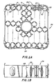
- the automated assembly apparatus of the present invention is disclosed in its embodiment devoted to assembling a multiplicity of fuel rod-positioning ferrules 22 into a matrix array to create a spacer, generally indicated at 24 in FIGURES 1, 1A and 1B.
- spacers are utilized to precisely maintain the relative positions of a plurality of nuclear fuel rods in a fuel bundle, as disclosed in U.S. Patent No. 4,508,679 and as generally indicated at 23 in FIGURE 1 herein.
- each ferrule bore provides a passage or cell through which an individual fuel rod 26 is inserted.
- the ferrule array is surrounded by a perimetrical band 28, to which the ferrules in the outermost rows and columns are conjoined at contiguous upper and lower edge points by suitable means, such as spot welds indicated at 29. Contiguous edges of adjacent ferrules are also conjoined by spot welds, indicated at 31, to create a rigid spacer assembly.
- suitable means such as spot welds indicated at 29. Contiguous edges of adjacent ferrules are also conjoined by spot welds, indicated at 31, to create a rigid spacer assembly.
- Suitable laser welding apparatus for this purpose is disclosed and claimed in our co-filed European Application No. based on US application Serial No. 279,010 filed on 2 December 1988 and entitled "System for Automated Welding of Parts Assembly in Controlled Environment".
- each fuel rod within a ferrule bore To position each fuel rod within a ferrule bore, the sidewall of each ferrule 22 is formed at each end with a pair of angularly spaced, inwardly projecting dimples or stops 30 of a precision stop height.
- Suitable stop forming apparatus is disclosed and claimed in our co-filed European Application No. based on US application Serial No. 279,009 filed on 2 December 1988 and entitled "Automated Forming Apparatus".
- Assembled with each different pair of ferrules is a double-acting, continuous loop spring 32 which serves to bias the fuel rods against the stops of the associated ferrule pair.
- the fuel rods are precisely centered within each ferrule bore.
- Automated apparatus for checking the stop height dimensions is disclosed in our co-filed European Application No. based on US application Serial No. 279,008 filed on 2 December 1988 and entitled "Automated Guaging Apparatus”.
- a C-shaped cutout 34 is cut into the sidewall of each ferrule, as seen in FIGURE 2, to provide a longitudinally elongated opening 34a and a circumferentially projecting tab 34b flanked by circumferentially extending notches 34c.
- circumferential slits 33 are cut into the ferrule sidewall to facilitate the formation of stops 30, and a notch 33 is cut into one edge of the ferrule to reference the relative angular positions of the slits and cutout.
- the automated assembly apparatus operates to successively assemble ferrules 22 into a properly oriented pair of ferrules, assemble a spring 32 to each pair, and then assemble the subassembled ferrule pair with captive spring into the matrix or "egg crate" formation seen in FIGURE 1A, all on an automated production line basis.
- the automated assembly apparatus includes a rotating table 36 which is indexed from a ferrule loading station, generally indicated at 38, a spring loading station, generally indicated at 40, a spring capturing station, generally indicated at 42, and a spacer assembly station, generally indicated at 44.
- This table carries four identical ferrule fixtures, generally indicated at 46, which are angularly spaced 90 o apart and thus are concurrently presented at each station. Consequently, the assembly of each ferrule pair and spring subassembly into a spacer 24 is accomplished in four steps of table 36. As each subassembly is assembled into a spacer at station 44, successive ferrule pairs are undergoing various stages of assembly at stations 42, 40 and 38.
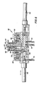
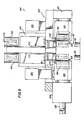
- each of the four ferrule pair fixtures 46 includes a fixture block 48 for mounting a pair of posts 50 and 52; the latter mounted on a pair of guide rods 53 for linear movement between a position juxtaposed post 50, as illustrated, and a position spaced therefrom under the motivation of an air cylinder 54.
- a ferrule 22 is inserted on each post while post 52 is in its spaced position relative to post 50.
- a pair of manipulator arms 56 are rotatably mounted by fixture block 48, each having an arcuate recess 57 partially surrounding a different one of the posts 50, 52 in closely spaced relation.
- Nubs 58 protruding from the surfaces of these arcuate recesses, are received in the indentations created in the ferrule peripheral surface by the formation of lower stops 30, such that the arms can drivingly engage the ferrules.
- the arms are provided with yokes 59 which engage pins 60 carried by rods 61 slidingly mounted by fixture block 48.
- rods 61 slidingly mounted by fixture block 48.
- fixed post 50 is, as best seen in the latter figure, provided with a vertically elongated cavity 62 for accommodating an upstanding blade 64 carried on a slide 65 mounted by fixture block 48.
- This slide is reciprocated by an air cylinder 66 to move the blade between its illustrated retracted position and a spring centering, closed position.
- Post 52 is formed with a shallow, vertically elongated notch 67. The confronting surfaces of blade 64 and notch 67 are conformed to the profile of spring 32.
- cavity 62 With the blade in its retracted position, cavity 62 is opened to receive a spring at station 40, which rests on a stop 68 projecting from post 52 into the cavity.
- ferrules 22 are fed successively from a suitable parts feeder, such as a vibratory bowl feeder (not shown), through an inclined delivery tube 72 to a shuttle 74 slideably mounted by a support structure 75, as seen in FIGURES 7 and 8.
- a suitable parts feeder such as a vibratory bowl feeder (not shown)
- This shuttle is actuated by an air cylinder 76 to laterally shift each ferrule 22 exiting the delivery tube onto a pair of elongated rollers 78 mounted in inclined, closely spaced parallel relation.
- These rollers are driven in counter-rotation by a motor 80 to impart unidirectional rotation to a ferrule supported thereon.
- each ferrule is keyed with a semicircular reference notch 33 which serves as an angular reference point utilized in the forming process to precisely locate stops 30 relative to C-shaped slot 34.
- rollers 78 in FIGURES 7 and 8 serve to rotate a ferrule as it gravitates toward a pin 84 upstanding between the rollers.
- pin 84 quickly finds and becomes lodged therein.
- a sensor 86 looks for the ferrule leading edge to detect if the notch has been found by pin 84. If it has, the pin is retracted by an air cylinder 88, and the ferrule gravitates therebeyond, as supported by the counter-rotating rollers.
- an inverter mechanism is provided to include a U-shaped arm 90 mounted at one end to a sector gear 92 journalled by support structure 75. This gear meshes with a rack gear 93 slideably mounted by the support structure for reciprocation by an air cylinder 94.
- the free end of the arm carries a thimble 95 which is normally poised above and in alignment with the axis of a ferrule supported in the rollers.
- air cylinder 94 is activated to stroke rack gear such as to swing arm 90 in the downhill direction as pin 84 is retracted.
- Thimble 95 is thus positioned to slip into the ferrule through its unnotched leading end as it gravitates along on rollers 78.
- Air cylinder 94 then strokes rack gear 93 in the opposite direction to swing the arm around to the point where the ferrule is dropped back into the rollers inverted end for end. The ferrule is thus reoriented with notch 33 in its leading edge. Pin 84 remains retracted to allow the ferrule to gravitate therepast on the rollers.
- a pairing shuttle 98 slidingly mounted by support structure 75 for transverse reciprocation by an air cylinder 100.
- a compression spring 101 biases this shuttle to quiescent position with its ferrule-receiving cavity 99 poised to accept each ferrule delivered thereto by rollers 78.
- Shuttle 98 is stroked back and forth through its quiescent position by air cylinder 100 to deposit successive accepted ferrules alternately into a pair of side-by-side delivery chutes 102.
- Ferrule detecting sensors (not shown) coordinate the operations of shuttles 74 and 98 such that, as each ferrule is accepted by the latter, the former transfers the next ferrule in delivery tube 72 to the rollers 78.
- the ferrules in chutes 102 are routed downwardly to a loading head, generally indicated at 104 in FIGURES 9, 10 and 11, where they are queued up by an escapement mechanism, generally indicated at 106.
- This mechanism includes, as seen in FIGURE 10, a plate 108 which is reciprocated by an air cylinder 110 to variously position a pair of ferrule stops 112 and 114 in each of a pair of side-by-side coextensive channels 116 in communication with the lower, exit ends of chutes 102.
- These escapements stops operate to release the ferrules, a pair at a time, to a orienting and loading mechanism, generally indicated at 120.
- this mechanism includes a pair of opposed rollers 122 which are rotatably mounted by separate yokes 124 and driven by separate motors 126. These yokes are slidingly mounted by guide blocks 128 for reciprocation by separate air cylinders 130.
- the lower ends of rollers 122 are provided with flanges 123 which serve as positioning stops for a ferrule pair released by escapement mechanism 106.
- Positioning springs 132 (FIGURE 9), carried by yokes 124, act against a mounting block 134 to ensure that the roller peripheries are clear of the ferrules as they drop down into abutment with the roller flanges 123.
- Mounting block 134 also supports a pair of arms 136 pivotally mounted intermediate their ends at 137.
- the illustrated lower ends of these arms carry locating wedges 138 which are biased by a compresson spring 139 acting in opposite directions against the arms at locations below their pivot points.
- the ferrules, supported on edge by the roller flanges 123, are thus urged against the roller peripheral surfaces by locating wedges 138.
- An air cylinder 140 is activated to drive its conically tipped plunger 141 between the illustrated upper ends of the arms to swing locating wedges 138 toward each other so as not to interfere with the descent of a pair of ferrules into abutment with their roller flange stops.
- plunger 141 Upon arrival of the ferrule pair thereat, plunger 141 is retracted, and locating wedges 138 urge the ferrules into driving engagement with rollers 122.
- the roller motors 126 are activated, and the ferrules are rotated on their axes with locating wedges 138 riding on the ferrule peripheral surfaces.
- the axial positions of the rotated ferrules are maintained by bearing rollers 143.
- the dimensions of these locating wedges are such that they can lodge in the longtudinal openings 34a of the ferrule C-shaped cutouts 34.
- the resulting incremental arm motion induced by spring 139, is sensed by a sensor 142 which issues a signal to deactivate the associated roller motor 126.
- FIGURE 11 when ferrule rotation is arrested by the locating wedges 138, the ferrules of the pair are angularly oriented with their cutout openings 34a in opposed, aligned relation.
- Air cylinders 130 are then signalled to retract the rollers 122 and clear the roller flanges from the lower flange edges.
- the ferrules then become resiliently clamped against arcuate surfaces 144 of mounting block 134 by compression spring 139 acting via arms 136 and their locating wedges 138 to preserve the achieved, requisitie ferrule angular orientation.
- an air cylinder 146 is activated to drive mounting block 134 downwardly to seat the ferrules on posts 50 and 52 of the ferrule fixture 46 (FIGURE 5) which has been indexed to ferrule loading station 38 by table 36.
- cam 150 and 152 are centrally mounted one over the other, relative to table 36, while a pair of air valves 154 and 156 are mounted to the table radially inwardly from each ferrule fixture 46. These valves are equipped with cam following actuators 155 and 157 which ride along on cams 150 and 152, respectively. From FIGURE 3, it is seen that cam 150 is formed with a lobe 151 which, when encountered by an actuator 155 positions its valve 154 to activate the air cylinder 54 of a ferrule pair fixture 46, causing ferrule post 52 to be retracted from its juxtaposed position with ferrule post 50 seen in FIGURE 5.
- This lobe is seen in FIGURE 3 to extend from a fixture position just beyond spacer assembly station 44 in the counterclockwise direction of table rotation (arrow 37) to a fixture position just beyond ferrule loading station 38.
- ferrule post 52 is retracted from ferrule post 50, such that these posts assume the requisite spaced apart relationship seen in FIGURE 9 aligned with the two ferrules held by loading block 134 as it descends to insert the angularly oriented ferrules on these posts.
- the valve actuator 155 rolls off the trailing edge of lobe 151.
- Fixture air cylinder 54 is then activated to translate post 52 into juxtaposition with post 50 to bring the cutout openings 34a of the ferrules thereon into intimate, face-to-face relation ready for the insertion of spring 32 upon arrival at station 40.
- the lobe 153 on cam 152 controls the actuation of blade positioning air cylinder 66 of each ferrule fixture 46 (FIGURE 5). Again as seen in FIGURE 3, this lobe extends counterclockwise from a fixture position just beyond spring loading station 40 to a fixture position just beyond spring capturing station 42. Until valve actuators 157 encounter lobe 153, their valves 152 activates the air cylinders of the associated ferrule fixtures 46 such as to position blades 64 to retracted positions seen in FIGURE 6. After insertion of a spring 32 into the opened cavity 62 in post 50 of a fixture 46 at station 40, lobe 153 is encountered by an valve actuator 157 as the fixture departs the station with next table step.
- valve actuator 157 rolls off the tailing end of lobe 153, and the blade 64 of this fixture is retracted. It will be appreciated that this blade retraction does not disturb the spring, since it has been interlocked in the closed notches 34c (FIGURE 2) of the ferrule pair.
- Spring loading station 40 includes an inclined delivery track 160 extending from a suitable serial parts feeder, such as a vibratory bowl feeder (not shown), for delivering a succession of springs 32 to a loading head 162.
- a suitable serial parts feeder such as a vibratory bowl feeder (not shown)
- the springs are queued up in a channel 164 formed in the loading head which is mounted by a support member 165 immediately above a ferrule fixture 46 in its spring loading station indexed position.
- the leading spring of this queue is stopped by a shuttle 166 in its illustrated leftmost position.
- This shuttle reciprocatingly mounted by the loading head, is stroked rightward by an air cylinder 168 to pick up the leading spring in a vertical shuttle cavity 169 and is then stroked leftward to align this cavity with an opening 170 in loading head 162.
- An air cylinder 172 is then activated to extend its plunger 173 and drive the spring downwardly out of shuttle cavity 169 through opening 170 into the cavity 62 left open by the retracted blade 64 of fixture post 50 (FIGURE 6).
- the air cylinder plunger 173 is retracted, and shuttle 166 picks up the next spring in the queue upon arrival of the next ferrule fixture at spring loading station 40.
- the loaded spring is centered in the aligned ferrule openings 34a by the shifting of blade 64 toward post 52 upon arrival of a fixture 46 at spring capturing station 42.
- an air cylinder 176 is mounted at station 42 on a stationary platform 178 underlying and extending beyond the perimeter of rotating table 36.
- a deck 180 mounted to this platform in elevated relation to table 36, carries a second air cylinder 182 also included at spring capturing station 42.
- the plunger 177 of air cylinder 176 and the depending extension 183 of the plunger for air cylinder 182 are positioned, upon actuation, to engage corresponding opposite ends of rods 61 (FIGURE 5).
- station 42 also includes an additional air cylinder 186 mounted by deck 180.
- the vertically oriented plunger of this air cylinder carries a hold-down pad 187 which is extended into lightly bearing engagement with the upper edges of the ferrules to prevent axial shifting thereof during spring capturing ferrule rotation induced by air cylinders 176 and 182.
- the spacer assembly station includes a pick and place mechanism, generally indicated at 190, operating to pick the the ferrule pair-spring subassembly from a fixture 46 presented thereto and place it in a spacer fixture, generally indicated at 192.
- the pick and place mechanism includes a transport base 194 operating to both vertically reciprocate along and horizontally rotate an arm 196 about an axis 195.
- an air cylinder 198 acting to vertically reciprocate gripper fingers 200 fashioned to pick a ferrule pair subassembly from a fixture 46.
- transport base 194 lifts arm 196 and rotates it to a position where gripper fingers 200 are vertically aligned with a fixture-borne ferrule pair subassembly presented at spacer assembly station 44.
- Air cylinder 198 is activated to reciprocate the gripper fingers and pick the subassembly from the fixture.
- Arm 196 is then rotated about axis 195 to swing the gripped subassembly around to a position above spacer fixture 192.
- Air cylinder 198 is again activated to place the ferrule pair assembly in the spacer fixture.
- spacer fixture 192 To this end, the spacer fixture is clamped to a precision, three-axis positioning table, generally indicated at 202. This table is programmed to linearly position the spacer fixture along orthogonal X and X axes, and to rotate it about a vertical Z axis. Thus, after each ferrule pair is placed in the spacer fixture, table 202 repositions the spacer fixture so that the next ferrule pair placement is made at an adjacent, vacant fixture location. As seen in FIGURE 14, spacer fixture 192 is provide an array of upstanding posts 193 located to guide the placements of successive ferrule pair subassemblies into precise positions throughout the fixture.
- fixture post 52 separation from fixture post 50 is initiated by cam 150, as previously described.
- an air cylinder 210, mounted on platform 178, and an air cylinder 212, mounted by deck 180 act on fixture rods 61 (FIGURE 5) to swing arms 56 back to their positions for accepting ferrules loaded onto the separated posts 50, 52 with the cutout openings 34a in confronting relation.
Landscapes
- Physics & Mathematics (AREA)
- Engineering & Computer Science (AREA)
- Plasma & Fusion (AREA)
- General Engineering & Computer Science (AREA)
- High Energy & Nuclear Physics (AREA)
- Automatic Assembly (AREA)
- Automobile Manufacture Line, Endless Track Vehicle, Trailer (AREA)
Applications Claiming Priority (2)
| Application Number | Priority Date | Filing Date | Title |
|---|---|---|---|
| US07/279,006 US4913707A (en) | 1988-12-02 | 1988-12-02 | Automated assembly apparatus |
| US279006 | 1988-12-02 |
Publications (2)
| Publication Number | Publication Date |
|---|---|
| EP0372785A2 true EP0372785A2 (de) | 1990-06-13 |
| EP0372785A3 EP0372785A3 (de) | 1990-08-22 |
Family
ID=23067284
Family Applications (1)
| Application Number | Title | Priority Date | Filing Date |
|---|---|---|---|
| EP89312321A Ceased EP0372785A3 (de) | 1988-12-02 | 1989-11-28 | Apparat zum automatisierten Zusammenbau |
Country Status (3)
| Country | Link |
|---|---|
| US (1) | US4913707A (de) |
| EP (1) | EP0372785A3 (de) |
| JP (1) | JPH0650350B2 (de) |
Cited By (1)
| Publication number | Priority date | Publication date | Assignee | Title |
|---|---|---|---|---|
| TWI761792B (zh) * | 2019-04-08 | 2022-04-21 | 美商惠普發展公司有限責任合夥企業 | 通過組件上編碼指令之組件裝配技術 |
Families Citing this family (11)
| Publication number | Priority date | Publication date | Assignee | Title |
|---|---|---|---|---|
| US5104033A (en) * | 1989-07-09 | 1992-04-14 | Honda Giken Kogyo Kabushiki Kaisha | System and apparatus for and method of assembling workpieces |
| US5257442A (en) * | 1989-09-07 | 1993-11-02 | Honda Giken Kabushiki Kaisha | Apparatus for assembling workpieces |
| JP3315151B2 (ja) * | 1992-07-02 | 2002-08-19 | 日高精機株式会社 | 熱交換器組立装置のパイプ挿入装置 |
| US5361288A (en) * | 1993-08-16 | 1994-11-01 | General Electric Company | Spacer with integral zircaloy springs |
| US5488644A (en) | 1994-07-13 | 1996-01-30 | General Electric Company | Spring assemblies for adjoining nuclear fuel rod containing ferrules and a spacer formed of the spring assemblies and ferrules |
| US5519747A (en) | 1994-10-04 | 1996-05-21 | General Electric Company | Apparatus and methods for fabricating spacers for a nuclear fuel rod bundle |
| US5546437A (en) | 1995-01-11 | 1996-08-13 | General Electric Company | Spacer for nuclear fuel rods |
| US5566217A (en) | 1995-01-30 | 1996-10-15 | General Electric Company | Reduced height spacer for nuclear fuel rods |
| US5675621A (en) | 1995-08-17 | 1997-10-07 | General Electric Company | Reduced height flat spring spacer for nuclear fuel rods |
| TW201640199A (zh) * | 2015-05-08 | 2016-11-16 | 鴻海精密工業股份有限公司 | 自動組裝裝置 |
| CN116586976B (zh) * | 2023-06-16 | 2023-10-31 | 惠州市祥胜智能装备有限公司 | 防水透气阀组装装置 |
Family Cites Families (11)
| Publication number | Priority date | Publication date | Assignee | Title |
|---|---|---|---|---|
| US3890196A (en) * | 1971-07-07 | 1975-06-17 | Atomic Energy Authority Uk | Nuclear reactor fuel element assembly spacer grid and method of making |
| US3858297A (en) * | 1973-06-11 | 1975-01-07 | Said Eitzinger By Said Butkus | Automatic springing machine |
| US4203206A (en) * | 1977-03-31 | 1980-05-20 | General Electric Company | Assembly machine |
| US4177548A (en) * | 1978-05-16 | 1979-12-11 | Owens-Illinois, Inc. | Method and device for assembling coaxially interfitting parts |
| US4178672A (en) * | 1978-05-17 | 1979-12-18 | Amico Peter J | Apparatus for assembling and banding an expansion shell |
| US4449294A (en) * | 1982-04-28 | 1984-05-22 | Robertshaw Controls Company | Apparatus for joining two abutting metal members together and method of making such apparatus |
| US4508679A (en) * | 1982-08-20 | 1985-04-02 | General Electric Company | Nuclear fuel assembly spacer |
| US4587704A (en) * | 1982-08-20 | 1986-05-13 | General Electric Company | Method of mounting a continuous loop spring on a nuclear fuel spacer |
| JPS5976636A (ja) * | 1982-10-22 | 1984-05-01 | Fuji Photo Film Co Ltd | ト−シヨンバネ成形供給方法 |
| FR2564020B1 (fr) * | 1984-05-10 | 1986-10-24 | Cogema Framatome Uranium Pechi | Dispositif de mise en place de ressorts en epingle a cheveux sur des plaquettes, notamment pour grilles d'assemblage de combustible |
| US4869865A (en) * | 1988-12-02 | 1989-09-26 | General Electric Company | Method of manufacturing nuclear fuel bundle spacers |
-
1988
- 1988-12-02 US US07/279,006 patent/US4913707A/en not_active Expired - Fee Related
-
1989
- 1989-11-27 JP JP1304969A patent/JPH0650350B2/ja not_active Expired - Lifetime
- 1989-11-28 EP EP89312321A patent/EP0372785A3/de not_active Ceased
Cited By (1)
| Publication number | Priority date | Publication date | Assignee | Title |
|---|---|---|---|---|
| TWI761792B (zh) * | 2019-04-08 | 2022-04-21 | 美商惠普發展公司有限責任合夥企業 | 通過組件上編碼指令之組件裝配技術 |
Also Published As
| Publication number | Publication date |
|---|---|
| JPH0650350B2 (ja) | 1994-06-29 |
| EP0372785A3 (de) | 1990-08-22 |
| US4913707A (en) | 1990-04-03 |
| JPH02201191A (ja) | 1990-08-09 |
Similar Documents
| Publication | Publication Date | Title |
|---|---|---|
| US4931615A (en) | Apparatus for machining intricate feature cuts in thin walled tubular parts | |
| US4913707A (en) | Automated assembly apparatus | |
| JP2681189B2 (ja) | 自動機械加工ライン用工作物支持アセンブリ | |
| EP0071302A1 (de) | Verfahren und Vorrichtung zum Zuführen von elektrischen und/oder elektronischen Bauelementen an vorbestimmte Stellen | |
| EP0223200B1 (de) | Maschine zum Zusammenbauen von Brennstoffbündeln | |
| US5808271A (en) | Method of laser beam welding interlaced straps of a spacer grid with plural beams | |
| JPH0335640B2 (de) | ||
| US4924586A (en) | Automated forming apparatus | |
| JP2585742B2 (ja) | 加工片取扱装置 | |
| JP2013516370A (ja) | 箱詰めされる製品のグループを形成するための装置および方法 | |
| US5415295A (en) | Method and device for automatically sorting nuclear-fuel pellets | |
| JPH0219798A (ja) | 核燃料集合体受入れ取りはずし用セル | |
| JP3139921B2 (ja) | 使用済燃料貯蔵ラックの製造方法とその製造装置 | |
| CN218431990U (zh) | 智能药品分包机临时药品加药移动分落装置 | |
| KR101424738B1 (ko) | 핵연료집합체 조립용 연료봉 자동적재장치 | |
| AU2002223529B2 (en) | Automated system for filling capillaries | |
| JPH036496A (ja) | 核燃料ペレット保持用の捕獲列収容トレー | |
| KR101575727B1 (ko) | 핵연료집합체의 연료봉 자동적재장치 | |
| CN220595959U (zh) | 一种输送回收装置及镜头全自动组装设备 | |
| US4068692A (en) | Fuel element loading system | |
| EP0471510B1 (de) | Zentriervorrichtung zur Verwendung während des Austausches der Brennelemente von wassergekühlten Kernreaktoren | |
| JPH04371330A (ja) | 円板の打抜き方法 | |
| JPH0221448Y2 (de) | ||
| CN115108312A (zh) | 有线接线盒的自动取料方法 | |
| RU2352446C2 (ru) | Станок для сборки тепловыделяющих элементов в тепловыделяющие сборки |
Legal Events
| Date | Code | Title | Description |
|---|---|---|---|
| PUAI | Public reference made under article 153(3) epc to a published international application that has entered the european phase |
Free format text: ORIGINAL CODE: 0009012 |
|
| AK | Designated contracting states |
Kind code of ref document: A2 Designated state(s): DE ES FR IT SE |
|
| PUAL | Search report despatched |
Free format text: ORIGINAL CODE: 0009013 |
|
| AK | Designated contracting states |
Kind code of ref document: A3 Designated state(s): DE ES FR IT SE |
|
| 17P | Request for examination filed |
Effective date: 19901210 |
|
| 17Q | First examination report despatched |
Effective date: 19930518 |
|
| STAA | Information on the status of an ep patent application or granted ep patent |
Free format text: STATUS: THE APPLICATION HAS BEEN REFUSED |
|
| 18R | Application refused |
Effective date: 19931113 |