EP0372787A2 - Appareil pour le formage automatique - Google Patents
Appareil pour le formage automatique Download PDFInfo
- Publication number
- EP0372787A2 EP0372787A2 EP89312323A EP89312323A EP0372787A2 EP 0372787 A2 EP0372787 A2 EP 0372787A2 EP 89312323 A EP89312323 A EP 89312323A EP 89312323 A EP89312323 A EP 89312323A EP 0372787 A2 EP0372787 A2 EP 0372787A2
- Authority
- EP
- European Patent Office
- Prior art keywords
- ferrule
- station
- die
- forming apparatus
- locating pin
- Prior art date
- Legal status (The legal status is an assumption and is not a legal conclusion. Google has not performed a legal analysis and makes no representation as to the accuracy of the status listed.)
- Ceased
Links
Images

Classifications
-
- G—PHYSICS
- G21—NUCLEAR PHYSICS; NUCLEAR ENGINEERING
- G21C—NUCLEAR REACTORS
- G21C3/00—Reactor fuel elements and their assemblies; Selection of substances for use as reactor fuel elements
- G21C3/30—Assemblies of a number of fuel elements in the form of a rigid unit
- G21C3/32—Bundles of parallel pin-, rod-, or tube-shaped fuel elements
- G21C3/34—Spacer grids
- G21C3/3424—Fabrication of spacer grids
-
- Y—GENERAL TAGGING OF NEW TECHNOLOGICAL DEVELOPMENTS; GENERAL TAGGING OF CROSS-SECTIONAL TECHNOLOGIES SPANNING OVER SEVERAL SECTIONS OF THE IPC; TECHNICAL SUBJECTS COVERED BY FORMER USPC CROSS-REFERENCE ART COLLECTIONS [XRACs] AND DIGESTS
- Y02—TECHNOLOGIES OR APPLICATIONS FOR MITIGATION OR ADAPTATION AGAINST CLIMATE CHANGE
- Y02E—REDUCTION OF GREENHOUSE GAS [GHG] EMISSIONS, RELATED TO ENERGY GENERATION, TRANSMISSION OR DISTRIBUTION
- Y02E30/00—Energy generation of nuclear origin
- Y02E30/30—Nuclear fission reactors
-
- Y—GENERAL TAGGING OF NEW TECHNOLOGICAL DEVELOPMENTS; GENERAL TAGGING OF CROSS-SECTIONAL TECHNOLOGIES SPANNING OVER SEVERAL SECTIONS OF THE IPC; TECHNICAL SUBJECTS COVERED BY FORMER USPC CROSS-REFERENCE ART COLLECTIONS [XRACs] AND DIGESTS
- Y10—TECHNICAL SUBJECTS COVERED BY FORMER USPC
- Y10T—TECHNICAL SUBJECTS COVERED BY FORMER US CLASSIFICATION
- Y10T29/00—Metal working
- Y10T29/53—Means to assemble or disassemble
- Y10T29/531—Nuclear device
-
- Y—GENERAL TAGGING OF NEW TECHNOLOGICAL DEVELOPMENTS; GENERAL TAGGING OF CROSS-SECTIONAL TECHNOLOGIES SPANNING OVER SEVERAL SECTIONS OF THE IPC; TECHNICAL SUBJECTS COVERED BY FORMER USPC CROSS-REFERENCE ART COLLECTIONS [XRACs] AND DIGESTS
- Y10—TECHNICAL SUBJECTS COVERED BY FORMER USPC
- Y10T—TECHNICAL SUBJECTS COVERED BY FORMER US CLASSIFICATION
- Y10T29/00—Metal working
- Y10T29/53—Means to assemble or disassemble
- Y10T29/5313—Means to assemble electrical device
- Y10T29/53187—Multiple station assembly apparatus
Definitions
- Nuclear power reactors are a well known source of energy.
- the nuclear fuel is comprised of elongated rods formed of sealed cladding tubes of suitable material, such as a zirconium alloy, containing uranium oxide and/or plutonium oxide as the nuclear fuel.
- suitable material such as a zirconium alloy
- uranium oxide and/or plutonium oxide as the nuclear fuel.
- a number of these fuel rods are grouped together and contained in an open-ended tubular flow channel to form a separately removable fuel assembly or bundle.
- a sufficient number of these fuel bundles are arranged in a matrix, approximating a right circular cylinder, to form the nuclear reactor core capable of self-sustained a fission reaction.
- the core is submerged in a fluid, such as light water, which serves both as a coolant and as a neutron moderator.
- a typical fuel bundle is formed by an array of fuel rods supported between upper and lower tie plates; the rods typically being in excess of ten feet in length, on the order of one-half inch in diameter and spaced from one another by a fraction of an inch.
- the rods typically being in excess of ten feet in length, on the order of one-half inch in diameter and spaced from one another by a fraction of an inch.
- a plurality of fuel rod spacers are thus utilized at spaced intervals along the length of the fuel bundle for this purpose.
- Design considerations of such fuel rod bundle spacers include the following: retention of rod-to-rod spacing; retention of fuel bundle shape; allowance for fuel rod thermal expansion; restriction of fuel rod vibration; ease of fuel bundle assembly; minimization of contact areas between spacer and fuel rods; maintenance of structural integrity of the spacer under normal and abnormal (such as seismic) loads; minimization of reactor coolant flow distortion and restriction; maximization of thermal limits; minimization of parasitic neutron absorption; and minimization of manufacturing costs including adaptation to automated production.
- a spacer is formed of an array of conjoined tubular ferrules surrounded by a peripheral support band, each ferrule thus providing a passage or cell through which a fuel rod or other elongated element of the fuel bundle is inserted,
- the ferrules are spot welded together and to a peripheral support band to provide an assembly of high structural strength, wherein the thickness of the metal used to form the peripheral support band and ferrules can be minimized to reduce coolant flow resistance and parasitic neutron absorption.
- Neutron absorption is further decreased by forming the ferrules and peripheral support band of low neutron absorption cross section material.
- the rods or elements extending through the ferrules are centered and laterally supports therein between rigid projections and a spring.
- These rigid projections or stops are formed as fluted or dimpled portions of the ferrule wall at locations near the upper and lower ferrule edges to maximize the axial distance therebetween and thus enhance fuel rod support.
- the stops are also angularly oriented to minimize projected area and thus disturbance of coolant flow.
- the formation of these stops in the ferrule sidewall must be accomplished with precision, and their height, as measured from adjacent points on the ferrule peripheral surface to the rod-engaging stop surface, is a critical dimension governing the precise centering of a fuel rod in the ferrule bore. Any eccentricity will adversely effect the uniform distribution of coolant flow through the fuel bundle.
- a typical large nuclear reactor core may include on the order of 800 fuel rod bundles, each with as many as seven spacers, and each spacer may comprise sixty fuel rod-positioning ferrules. From this, it is seen that automated, expedited production of these ferrules is of vital importance.
- an automated apparatus for imparting surface features to the walls of tubular parts in which the parts, specifically nuclear fuel rod spacer ferrules in the illustrated embodiment of the invention, are delivered seriatim to a first station where they are arranged in a predetermined end-to-end orientation using a keying feature cut into one edge of the ferrule. From this first station, the ferrules are successively delivered to a second station where they are arranged in a predetermined angular orientation using the same keying feature.
- a pick and place mechanism transfers each oriented ferrule from the second station to a forming die mounted in a hydraulic press. The die closes to clamp the ferrule and provide back-up for the peripheral and edge surfaces of the ferrule.
- An expanding back-up mandrel is cammed into the ferrule bore as the press forming stroke begins.
- Two pairs of punches are pressed into contact with the ferrule to form the plural ferrule stops as dimpled or fluted portions of the ferrule sidewall.
- the formed ferrule is pushed therefrom into an extractor by the placement of the next ferrule into the die by the pick and place mechanism.
- the extractor deposits the formed ferrule in an output chute.
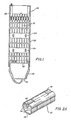
- a fuel bundle generally indicated at 20 in FIGURE 1, comprises a plurality of fuel elements or rods 21 supported between a skeletonized upper tie plate 22 and a skeletonized lower tie plate 23.
- the fuel rods 21 pass through a plurality of fuel rod spacers 24 which provide intermediate support to retain the elongated rods in spaced relation and restrain them from lateral vibration.
- the fuel bundle 20 further includes a thin-walled tubular flow channel 25 of substantially square cross section, sized to form a sliding fit over the upper and lower tie plates 22 and 23 and the spacers 24 so that the channel may readily be mounted and removed.
- the lower tie plate 23 is formed with a nose piece 29 adapted to support the fuel bundle 20 in a socket of a core support plate (not shown) in the reactor pressure vessel. The end of this nose piece is formed with openings 30 to receive pressurized coolant which flows upwardly through the fuel bundle.
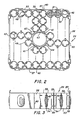
- Each spacer 24, as seen in FIGURES 2 and 3, is made up of ferrules 32 arranged in a matrix array with their points of peripheral abutment conjoined by welding at their upper and lower edges, as illustrated at 33 and 34.
- the bore of ferrule provides a passage for an elongated element of the fuel assembly, such as fuel rod 21.
- a perimetrical band 36 is conjoined to the upper and lower edges of the peripheral ferrules of the assembled matrix at their points of abutment by spot welds 37 and 38.
- This peripheral support band is assembled in four similar L-shaped pieces, each positioned about a corner of the ferrule array with their abutting ends joined by a seam weld 40.
- Straps 41 are welded, as indicated at 42, to the ferrules bounding a central opening in spacer 24 for accommodating a water pipe 43.
- Pipe-engaging springs 44 are carried by a pair of these straps to prevent vibration.
- Fuel rods 21, or other elongated elements, extending through the ferrule bores are centered and laterally supported therein between a resilient spring 46 and generally oppositely positioned axially spaced pairs of relatively rigid projections or stops 48 (FIGURE 2A) integrally formed by the apparatus of the present invention seen in FIGURE 4 as longitudinally spaced pairs of inwardly projecting, fluted or dimpled portions of the ferrule wall near the upper and lower edges thereof.
- circumferential slits 52 are cut into the ferrule sidewall by a prior laser cutting operation such as disclosed in our co-filed European Application No. entitled "Apparatus for Machining Intricate Feature Cuts in Thin Walled Tubular Parts", based on U.S.
- C-shaped cutouts 50 are created in the ferrule sidewall to accommodate the capture of spring 46 in a subassembled pair of ferrules as described in U.S. Patent No. 4,508,679. Also a keying notch 55 is cut into one edge of each ferrule at a location referenced to the positions of slits 52 and cutout 50.
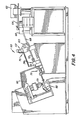
- the automated forming apparatus of the present invention includes an elevated hopper 62 containing a quantity of ferrules, each having the sidewall feature cuts 55, 50 and 52.
- the hopper is vibrated on demand to discharge ferrules onto an output tray 64 leading to a vibratory bowl feeder 66.
- This feeder operates to arrange the ferrules in serial order for successive feeding into an inclined delivery tube 68 leading to a first station, generally indicated at 70 and detailed in FIGURES 5 and 6.
- This station operates automatically to longitudinally reorient each ferrule end-for-end, if necessary, using edge notch 55.
- the longitudinally oriented ferrules gravitate through an inclined delivery tube 72 to a second station, generally indicated at 74 and also detailed in FIGURES 5 and 6, where the successive ferrules are automatically positioned to a prescribed angular orientation in a pickup position, again using edge notch 55.
- a conventional pick and place mechanism is equipped with a pair of fingers 78 which are inserted into the bore of the angularly oriented ferrule in station 74. The fingers are separated to engage the ferrule bore, thus securely gripping the ferrule.
- the pick and place mechanism is articulated to extract the ferrule from station 74, swing the extracted ferrule through a 180° arc, and place it in the open die 79 of a hydraulic punch press, generally indicated at 80.
- a punch press cycle is initiated wherein the die is closed to clamp the ferrule in place and to fully back-up the ferrule peripheral and edge surfaces.
- the gripper fingers 78 are then withdrawn, and the pick and place mechanism articulates to pick up the next oriented ferrule waiting in the pickup position in station 74.
- a mandrel Prior to stop-forming contact with the ferrule in die 79, a mandrel is inserted into the ferrule bore to provide interior surface back up. Once the stops 48 are formed, the die opens up, and the formed ferrule is pushed from the die by the insertion thereinto of the next ferrule by pick and place mechanism 76.
- An extractor shuttle 122 reciprocated by an air cylinder 124, accepts the discharged, formed ferrule from the die and transfers it to an output chute 82, as seen in FIGURE 7.
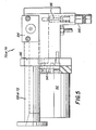
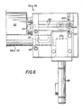
- Stations 70 and 74 are of the same basic construction illustrated in FIGURES 5 and 6.
- ferrules arrive through delivery tube 68 in the case of station 70 (delivery tube 72 in the case of station 74) where they queue up against a transfer shuttle 84 slideably mounted by a fixture 86 for reciprocation by an air cylinder 88.
- the shuttle picks up the leading ferrule and transfers it laterally onto a pair of inclined rollers 90 journalled by the fixture in closely spaced, parallel relation.
- These rollers are driven in counter rotation by a motor 92 via gearing 94 to impart axial rotation in one direction to a ferrule supported thereon.
- a locating pin 96 retractable by an air cylinder 98, projects upwardly between the rollers in a position to intercept the leading edge of a ferrule as it gravitates thereto.
- sensors 100 (FIGURE 7) are positioned to look for the ferrule leading edge. If the ferrule leading edge contains notch 55, locating pin 96 becomes lodged therein, allowing incremental forward movement of the ferrule sufficient to enable these sensors to detect the leading edge.
- air cylinder 88 is signalled to retract the locating pin, and a ferrule with the desired longitudinal orientation is permitted to gravitate off of rollers 90 and into delivery tube 72 leading to station 74.
- sensors 100 signal an inverting mechanism, generally indicated at 102 in FIGURE 4, into action.
- This mechanism includes a pair of fingers 103 which descend to grasp the ferrule held by the locating pin, raise the ferrule, rotate it end-for-end, and replace the longitudinally reoriented ferrule on rollers 90.
- locating pin 96 is retracted enabling the ferrule to gravitate, notched edge first, off the rollers and into delivery tube 72.
- ferrules of the requisite longitudinal orientation are singulated by a reciprocating shuttle 84 for successive lateral transfer onto a set of inclined, counter-rotating rollers 90 where it is axially rotated until its notch 55 is located by a pin 96.
- motor 92 is signalled to stop by sensors 100, and the ferrule, now properly angularly oriented in a pickup position, awaits pick up by pick and place mechanism 76.
- locating pin 96 is retracted by its air cylinder 98, clearing the ferrule for extraction from station 74 and transfer to punch press 80.
- FIGURE 7 depicts die 79 in its closed condition to preserve the angular orientation of the ferrule 32 achieved in station 74 and to back up the ferrule peripheral surface.
- Interior surface back-up is provided by an expandable mandrel 110 which, as the press strokes downwardly, is cammed into the ferrule bore after the ferrule has been clamped in the die and pick and place fingers 78 have been retracted.
- An end plate 112 resiliently mounted to the movable upper die half 114 is cammed against the outer edge of the ferrule by overlapping tapered blocks 116 affixed to the stationary lower die half 118 during the final stage of die closure. This edge backup prevents metal outflow as stops 48 are formed.
- Ferrule inner edge backup is provided by a plate (not shown) affixed to upper die 114 and backed up by a mandrel mounting block (not shown). With die 79 fully closed, two sets of fore and aft punches 120 are pressed into stop forming engagement with the ferrule. When a preset pressure is achieved, the press stroke is reversed, withdrawing the punches and opening the die. The formed ferrule 32 is left in the lower die half to be pushed out by the next ferrule being placed in the die by the pick and place mechanism.
- An extractor shuttle 122 is positioned rearwardly of the die by its air cylinder 124 to accept the discharged ferrule and is then repositioned to deposit the ferrule in output chute 82, seen also in FIGURE 4.
- This chute routes the ferrules to an automated stop height gauging apparatus such as disclosed and claimed in our co-filed European Application No. based on U.S. Serial No. 279,008 and entitled "Automated Gauging Apparatus".
- apparatus for forming surface features in tubular parts wherein the parts are automatically positioned to a requisite orientation prior to forming.
- the apparatus is used for creating precision nuclear fuel rod-positioning stops in the sidewalls of ferrules utilized in nuclear fuel bundle spacers, these ferrule stops being formed at predetermined plural locations on a multiplicity of spacer ferrules in rapid succession.
Landscapes
- Physics & Mathematics (AREA)
- Engineering & Computer Science (AREA)
- Plasma & Fusion (AREA)
- General Engineering & Computer Science (AREA)
- High Energy & Nuclear Physics (AREA)
- Automatic Assembly (AREA)
- Monitoring And Testing Of Nuclear Reactors (AREA)
- Forging (AREA)
- Extrusion Moulding Of Plastics Or The Like (AREA)
- Press-Shaping Or Shaping Using Conveyers (AREA)
- Mechanical Coupling Of Light Guides (AREA)
Applications Claiming Priority (2)
| Application Number | Priority Date | Filing Date | Title |
|---|---|---|---|
| US07/279,009 US4924586A (en) | 1988-12-02 | 1988-12-02 | Automated forming apparatus |
| US279009 | 2002-10-24 |
Publications (2)
| Publication Number | Publication Date |
|---|---|
| EP0372787A2 true EP0372787A2 (fr) | 1990-06-13 |
| EP0372787A3 EP0372787A3 (fr) | 1990-08-22 |
Family
ID=23067295
Family Applications (1)
| Application Number | Title | Priority Date | Filing Date |
|---|---|---|---|
| EP89312323A Ceased EP0372787A3 (fr) | 1988-12-02 | 1989-11-28 | Appareil pour le formage automatique |
Country Status (3)
| Country | Link |
|---|---|
| US (1) | US4924586A (fr) |
| EP (1) | EP0372787A3 (fr) |
| JP (1) | JPH02212798A (fr) |
Cited By (4)
| Publication number | Priority date | Publication date | Assignee | Title |
|---|---|---|---|---|
| FR2715761A1 (fr) * | 1992-10-29 | 1995-08-04 | Westinghouse Electric Corp | Procédé pour fabriquer une grille d'assemblage combustible nucléaire et grille à l'aide de ce procédé. |
| RU2155394C1 (ru) * | 1999-02-17 | 2000-08-27 | Открытое акционерное общество "Новосибирский завод химконцентратов" | Установка контроля и разбраковки тепловыделяющих элементов |
| RU2170961C2 (ru) * | 1999-06-09 | 2001-07-20 | Открытое акционерное общество "Новосибирский завод химконцентратов" | Линия контроля и разбраковки тепловыделяющих элементов |
| RU2696001C1 (ru) * | 2018-11-16 | 2019-07-30 | Публичное акционерное общество "Машиностроительный завод" | Установка для контроля альфа-загрязненности тепловыделяющих элементов |
Families Citing this family (11)
| Publication number | Priority date | Publication date | Assignee | Title |
|---|---|---|---|---|
| JP2510752B2 (ja) * | 1990-03-19 | 1996-06-26 | 株式会社日立製作所 | 燃料スペ―サの製造方法 |
| FR2665293B1 (fr) * | 1990-07-24 | 1993-12-24 | Framatome | Procede de fabrication de grille a cellules calibrees pour assemblage combustible nucleaire. |
| US5361288A (en) * | 1993-08-16 | 1994-11-01 | General Electric Company | Spacer with integral zircaloy springs |
| US5488644A (en) | 1994-07-13 | 1996-01-30 | General Electric Company | Spring assemblies for adjoining nuclear fuel rod containing ferrules and a spacer formed of the spring assemblies and ferrules |
| US5519747A (en) | 1994-10-04 | 1996-05-21 | General Electric Company | Apparatus and methods for fabricating spacers for a nuclear fuel rod bundle |
| US5546437A (en) | 1995-01-11 | 1996-08-13 | General Electric Company | Spacer for nuclear fuel rods |
| US5566217A (en) | 1995-01-30 | 1996-10-15 | General Electric Company | Reduced height spacer for nuclear fuel rods |
| US5675621A (en) | 1995-08-17 | 1997-10-07 | General Electric Company | Reduced height flat spring spacer for nuclear fuel rods |
| US6457343B1 (en) * | 2001-03-06 | 2002-10-01 | Larry Shed | Tubing swaging machine |
| SE530864C2 (sv) * | 2007-02-05 | 2008-09-30 | Westinghouse Electric Sweden | Förfarande för framställning av spridare för kärnreaktor |
| CN114005561B (zh) * | 2021-10-29 | 2022-10-04 | 华能山东石岛湾核电有限公司 | 一种高温气冷堆燃料元件输送控制方法及系统 |
Family Cites Families (7)
| Publication number | Priority date | Publication date | Assignee | Title |
|---|---|---|---|---|
| US2006283A (en) * | 1934-07-19 | 1935-06-25 | Staempfli Joseph | Machine for making boiler cleaner nozzles |
| US4177548A (en) * | 1978-05-16 | 1979-12-11 | Owens-Illinois, Inc. | Method and device for assembling coaxially interfitting parts |
| DE3015893A1 (de) * | 1980-04-24 | 1981-10-29 | Hilti AG, 9494 Schaan | Verfahren zum herstellen von mitnahmenuten an werkzeugen |
| CH660313A5 (de) * | 1984-04-24 | 1987-04-15 | Stopinc Ag | Verfahren zur herstellung einer verschlussplatteneinheit fuer einen schiebeverschluss. |
| FR2564020B1 (fr) * | 1984-05-10 | 1986-10-24 | Cogema Framatome Uranium Pechi | Dispositif de mise en place de ressorts en epingle a cheveux sur des plaquettes, notamment pour grilles d'assemblage de combustible |
| JPH0769449B2 (ja) * | 1987-09-28 | 1995-07-31 | 株式会社日立製作所 | 独立セル型燃料スペーサおよびその製造方法 |
| US4869865A (en) * | 1988-12-02 | 1989-09-26 | General Electric Company | Method of manufacturing nuclear fuel bundle spacers |
-
1988
- 1988-12-02 US US07/279,009 patent/US4924586A/en not_active Expired - Fee Related
-
1989
- 1989-11-28 EP EP89312323A patent/EP0372787A3/fr not_active Ceased
- 1989-12-01 JP JP1310825A patent/JPH02212798A/ja active Granted
Cited By (5)
| Publication number | Priority date | Publication date | Assignee | Title |
|---|---|---|---|---|
| FR2715761A1 (fr) * | 1992-10-29 | 1995-08-04 | Westinghouse Electric Corp | Procédé pour fabriquer une grille d'assemblage combustible nucléaire et grille à l'aide de ce procédé. |
| RU2155394C1 (ru) * | 1999-02-17 | 2000-08-27 | Открытое акционерное общество "Новосибирский завод химконцентратов" | Установка контроля и разбраковки тепловыделяющих элементов |
| RU2170961C2 (ru) * | 1999-06-09 | 2001-07-20 | Открытое акционерное общество "Новосибирский завод химконцентратов" | Линия контроля и разбраковки тепловыделяющих элементов |
| RU2696001C1 (ru) * | 2018-11-16 | 2019-07-30 | Публичное акционерное общество "Машиностроительный завод" | Установка для контроля альфа-загрязненности тепловыделяющих элементов |
| WO2020101527A1 (fr) * | 2018-11-16 | 2020-05-22 | Публичное акционерное общество "Машиностроительный завод" | Installation de contrôle de contamination par particules alpha de la surface de crayons de combustible |
Also Published As
| Publication number | Publication date |
|---|---|
| JPH0536140B2 (fr) | 1993-05-28 |
| US4924586A (en) | 1990-05-15 |
| JPH02212798A (ja) | 1990-08-23 |
| EP0372787A3 (fr) | 1990-08-22 |
Similar Documents
| Publication | Publication Date | Title |
|---|---|---|
| US4924586A (en) | Automated forming apparatus | |
| EP0372789A2 (fr) | Appareil pour usiner des coupes compliquées dans des éléments à parois minces | |
| CN1131761C (zh) | 热交换器的热交换器用管组装装置及组装方法 | |
| US20040025560A1 (en) | Radioactive substance containment vessel, and radioactive substance contaiment vessel producing device and producing method | |
| EP2120241A1 (fr) | Dispositif destiné à contenir des cibles d'irradiation, assemblage de combustible comprenant de telles cibles, et procédé d'utilisation associé | |
| US4946587A (en) | Automated gauging apparatus | |
| EP0017508B1 (fr) | Extracteur comportant des ressorts en lamelles pour barreaux de combustible nucléaire | |
| US4869865A (en) | Method of manufacturing nuclear fuel bundle spacers | |
| RU2145449C1 (ru) | Автоматическая линия изготовления тепловыделяющих элементов | |
| US4913707A (en) | Automated assembly apparatus | |
| EP0334069B1 (fr) | Système pour former une colonne de pastilles de combustible nucléaire | |
| EP0361916A2 (fr) | Fabrication d'une section d'une barre absorbante de contrôle par une configuration des tubes carrés et procédé de soudure par laser | |
| US4684498A (en) | Guide thimble captured locking tube in a reconstitutable fuel assembly | |
| RU2155395C1 (ru) | Автоматическая линия изготовления тепловыделяющих элементов | |
| RU2094866C1 (ru) | Автоматизированная линия сборки твэл для энергетических ядерных реакторов типа бн | |
| US4716018A (en) | End plug with truncated tapered leading end configuration | |
| EP0268807B1 (fr) | Système de fixation pour l'embout inférieur d'un assemblage de combustible nucléaire permettant une reconstitution | |
| JPH0219798A (ja) | 核燃料集合体受入れ取りはずし用セル | |
| US4723358A (en) | Apparatus for inserting rods containing nuclear fuel or neutron absorber material in a predetermined dense packing in a vessel | |
| EP0300246A2 (fr) | Dispositif pour transporter des pastilles de combustible nucléaire d'une presse pour pastilles à une nacelle de frittage | |
| US4788026A (en) | Nuclear fuel assembly grid sleeve/guide thimble bulge orientation gage and inspection method | |
| EP0490127A1 (fr) | Méthode pour former une cavité de prise dans un bouchon terminal d'un barreau combustible | |
| JPS63106225A (ja) | 円柱体の方向転換機 | |
| KR100817435B1 (ko) | 핵연료집합체의 안내관 플랜지 자동접합장치 및 방법 | |
| EP0168727B1 (fr) | Appareil pour couper des tubes concentriques assemblés par élargissement |
Legal Events
| Date | Code | Title | Description |
|---|---|---|---|
| PUAI | Public reference made under article 153(3) epc to a published international application that has entered the european phase |
Free format text: ORIGINAL CODE: 0009012 |
|
| AK | Designated contracting states |
Kind code of ref document: A2 Designated state(s): CH DE ES IT LI NL SE |
|
| PUAL | Search report despatched |
Free format text: ORIGINAL CODE: 0009013 |
|
| AK | Designated contracting states |
Kind code of ref document: A3 Designated state(s): CH DE ES IT LI NL SE |
|
| 17P | Request for examination filed |
Effective date: 19901210 |
|
| 17Q | First examination report despatched |
Effective date: 19930518 |
|
| STAA | Information on the status of an ep patent application or granted ep patent |
Free format text: STATUS: THE APPLICATION HAS BEEN REFUSED |
|
| 18R | Application refused |
Effective date: 19931113 |