EP0373013B1 - Mit einer Abreisslippe versehenes, abdichtendes Garantieband und mit einem solchen Band versehener Behälter - Google Patents
Mit einer Abreisslippe versehenes, abdichtendes Garantieband und mit einem solchen Band versehener Behälter Download PDFInfo
- Publication number
- EP0373013B1 EP0373013B1 EP89403083A EP89403083A EP0373013B1 EP 0373013 B1 EP0373013 B1 EP 0373013B1 EP 89403083 A EP89403083 A EP 89403083A EP 89403083 A EP89403083 A EP 89403083A EP 0373013 B1 EP0373013 B1 EP 0373013B1
- Authority
- EP
- European Patent Office
- Prior art keywords
- strip
- sealing strip
- tear
- container
- sealing
- Prior art date
- Legal status (The legal status is an assumption and is not a legal conclusion. Google has not performed a legal analysis and makes no representation as to the accuracy of the status listed.)
- Expired - Lifetime
Links
- 238000007789 sealing Methods 0.000 title claims abstract description 129
- 239000010410 layer Substances 0.000 claims description 9
- 229920002799 BoPET Polymers 0.000 claims description 5
- 239000005041 Mylar™ Substances 0.000 claims description 5
- 239000000463 material Substances 0.000 claims description 5
- 239000012790 adhesive layer Substances 0.000 claims description 4
- 239000000853 adhesive Substances 0.000 description 6
- 230000001070 adhesive effect Effects 0.000 description 6
- 238000004519 manufacturing process Methods 0.000 description 4
- 230000015572 biosynthetic process Effects 0.000 description 3
- 229920003023 plastic Polymers 0.000 description 3
- 239000004033 plastic Substances 0.000 description 3
- XTXRWKRVRITETP-UHFFFAOYSA-N Vinyl acetate Chemical compound CC(=O)OC=C XTXRWKRVRITETP-UHFFFAOYSA-N 0.000 description 2
- 230000000295 complement effect Effects 0.000 description 2
- 229920000915 polyvinyl chloride Polymers 0.000 description 2
- 239000004800 polyvinyl chloride Substances 0.000 description 2
- 238000007493 shaping process Methods 0.000 description 2
- 125000000391 vinyl group Chemical group [H]C([*])=C([H])[H] 0.000 description 2
- 239000004593 Epoxy Substances 0.000 description 1
- BQCADISMDOOEFD-UHFFFAOYSA-N Silver Chemical compound [Ag] BQCADISMDOOEFD-UHFFFAOYSA-N 0.000 description 1
- 150000001252 acrylic acid derivatives Chemical class 0.000 description 1
- 239000003795 chemical substances by application Substances 0.000 description 1
- 238000000576 coating method Methods 0.000 description 1
- 230000002860 competitive effect Effects 0.000 description 1
- 238000006073 displacement reaction Methods 0.000 description 1
- -1 e.g. Chemical class 0.000 description 1
- 125000003700 epoxy group Chemical group 0.000 description 1
- MEGHWIAOTJPCHQ-UHFFFAOYSA-N ethenyl butanoate Chemical class CCCC(=O)OC=C MEGHWIAOTJPCHQ-UHFFFAOYSA-N 0.000 description 1
- PCHJSUWPFVWCPO-UHFFFAOYSA-N gold Chemical compound [Au] PCHJSUWPFVWCPO-UHFFFAOYSA-N 0.000 description 1
- 229910052737 gold Inorganic materials 0.000 description 1
- 239000010931 gold Substances 0.000 description 1
- 238000007689 inspection Methods 0.000 description 1
- 238000004806 packaging method and process Methods 0.000 description 1
- 239000002985 plastic film Substances 0.000 description 1
- 229920006255 plastic film Polymers 0.000 description 1
- 229920000647 polyepoxide Polymers 0.000 description 1
- 239000002243 precursor Substances 0.000 description 1
- 229910052709 silver Inorganic materials 0.000 description 1
- 239000004332 silver Substances 0.000 description 1
- 238000013022 venting Methods 0.000 description 1
- 229920001567 vinyl ester resin Polymers 0.000 description 1
- 229920002554 vinyl polymer Polymers 0.000 description 1
Images

Classifications
-
- B—PERFORMING OPERATIONS; TRANSPORTING
- B65—CONVEYING; PACKING; STORING; HANDLING THIN OR FILAMENTARY MATERIAL
- B65D—CONTAINERS FOR STORAGE OR TRANSPORT OF ARTICLES OR MATERIALS, e.g. BAGS, BARRELS, BOTTLES, BOXES, CANS, CARTONS, CRATES, DRUMS, JARS, TANKS, HOPPERS, FORWARDING CONTAINERS; ACCESSORIES, CLOSURES, OR FITTINGS THEREFOR; PACKAGING ELEMENTS; PACKAGES
- B65D77/00—Packages formed by enclosing articles or materials in preformed containers, e.g. boxes, cartons, sacks or bags
- B65D77/22—Details
- B65D77/30—Opening or contents-removing devices added or incorporated during filling or closing of containers
- B65D77/32—Tearing-strings or like flexible elements
-
- B—PERFORMING OPERATIONS; TRANSPORTING
- B65—CONVEYING; PACKING; STORING; HANDLING THIN OR FILAMENTARY MATERIAL
- B65D—CONTAINERS FOR STORAGE OR TRANSPORT OF ARTICLES OR MATERIALS, e.g. BAGS, BARRELS, BOTTLES, BOXES, CANS, CARTONS, CRATES, DRUMS, JARS, TANKS, HOPPERS, FORWARDING CONTAINERS; ACCESSORIES, CLOSURES, OR FITTINGS THEREFOR; PACKAGING ELEMENTS; PACKAGES
- B65D55/00—Accessories for container closures not otherwise provided for
- B65D55/02—Locking devices; Means for discouraging or indicating unauthorised opening or removal of closure
- B65D55/06—Deformable or tearable wires, strings or strips; Use of seals
- B65D55/08—Annular elements encircling container necks
- B65D55/0818—Destructible or permanently removable bands, e.g. adhesive
-
- Y—GENERAL TAGGING OF NEW TECHNOLOGICAL DEVELOPMENTS; GENERAL TAGGING OF CROSS-SECTIONAL TECHNOLOGIES SPANNING OVER SEVERAL SECTIONS OF THE IPC; TECHNICAL SUBJECTS COVERED BY FORMER USPC CROSS-REFERENCE ART COLLECTIONS [XRACs] AND DIGESTS
- Y10—TECHNICAL SUBJECTS COVERED BY FORMER USPC
- Y10S—TECHNICAL SUBJECTS COVERED BY FORMER USPC CROSS-REFERENCE ART COLLECTIONS [XRACs] AND DIGESTS
- Y10S428/00—Stock material or miscellaneous articles
- Y10S428/906—Roll or coil
-
- Y—GENERAL TAGGING OF NEW TECHNOLOGICAL DEVELOPMENTS; GENERAL TAGGING OF CROSS-SECTIONAL TECHNOLOGIES SPANNING OVER SEVERAL SECTIONS OF THE IPC; TECHNICAL SUBJECTS COVERED BY FORMER USPC CROSS-REFERENCE ART COLLECTIONS [XRACs] AND DIGESTS
- Y10—TECHNICAL SUBJECTS COVERED BY FORMER USPC
- Y10T—TECHNICAL SUBJECTS COVERED BY FORMER US CLASSIFICATION
- Y10T428/00—Stock material or miscellaneous articles
- Y10T428/15—Sheet, web, or layer weakened to permit separation through thickness
-
- Y—GENERAL TAGGING OF NEW TECHNOLOGICAL DEVELOPMENTS; GENERAL TAGGING OF CROSS-SECTIONAL TECHNOLOGIES SPANNING OVER SEVERAL SECTIONS OF THE IPC; TECHNICAL SUBJECTS COVERED BY FORMER USPC CROSS-REFERENCE ART COLLECTIONS [XRACs] AND DIGESTS
- Y10—TECHNICAL SUBJECTS COVERED BY FORMER USPC
- Y10T—TECHNICAL SUBJECTS COVERED BY FORMER US CLASSIFICATION
- Y10T428/00—Stock material or miscellaneous articles
- Y10T428/24—Structurally defined web or sheet [e.g., overall dimension, etc.]
- Y10T428/24479—Structurally defined web or sheet [e.g., overall dimension, etc.] including variation in thickness
- Y10T428/2457—Parallel ribs and/or grooves
Definitions
- This invention relates to a combination of a spoolable sealing strip and a carrier therefor the combination including a tear tab and tear strip according to the preamble of claim 1. Further, this invention relates to the use of the combination, claim 10, and to a seal for a container according to the preamble of claim 11.
- the lid and the body of the container In order to mass produce such containers, the lid and the body of the container must be so shaped as to allow proper seating of the lid on the container.
- plastic materials which have a reasonably good flexibility. Plastic materials allow diverse shaping of the container body for reception of the lid, as well as the shaping of a complementary lid.
- Tear tabs which embody a tear strip or strings have, according to the prior art, a fairly thick central section for the tear strip or string.
- Various layers which are used for the sealing of the closure make it difficult to place accurately a seal on such containers or to seal properly such containers, because the spooled sealing strip is displaced sideways as the spool is wound up.
- the present invention is to eliminate and/or minimize the above recited problems.
- a combination of a spoolable sealing strip and a carrier having the features and capabilities of claim 1.
- Subclaims 2 to 9 relate to prefered enhancements of such combination.
- a seal for a container having the features of claim 11.
- Subclaims 12 to 14 relate to prefered embodiments of this seal.
- sealing strip embodiments have been discovered which provide spoolable sealing strips, including sealing strips with a tear tab and a tear strip therefor.
- the tear tab or the tear tab and its tear strip are part of the sealing strip carrier.
- the exposed tear tab with a tear strip conveniently identifies, or makes evident, any tampering of the container by a mere observation of the container.
- the container can now be readily opened by merely pulling on the tear tab which allows the tear strip to sever a pre-scored portion of the entire sealing strip, and thus to remove the seal.
- Such manipulation provides a ready opening of the container and the removal of the lid therefrom.
- a sealing strip for a closure as described before is used in combination with containers which allows now a high speed sealing of containers.
- a specifically designed container configuration is integrated with the sealing strip to provide for a container closure in such a manner as to allow the use of spoolable, high speed, yet accurate, sealing strip placement on a container.
- the present invention allows for a substantially hermetical sealing of containers by means of the tamper-evident sealing strips.
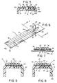
- FIG. 1 illustrates the container 10 having placed thereon a sealing strip 11.
- sealing strip 11 consists of an elongate body 12 and round end portions 12a and 12b therefor; end portion 12b carries a tear tab 14 which has a narrowed neck 13 terminating in tear strip 14a. Cut lines 15 are on both sides of the neck 13 portion of sealing strip 11.
- Tear strip 14a is thus interconnected to neck 13 and tear tab 14. Tear strip 14a is scored along score lines 17, shown as extending for the entire length of sealing strip elongate body 12.
- sealing strip 11 is removed from carrier 16. That is, carrier 16 is in a form of a Mylar film, as is the sealing strip elongate body 12. Other like plastic films may be used, such as vinyl, vinyl acetate, etc., but Mylar is preferred.
- Sealing strip 11 is readily peeled back from carrier 16, as shown for illustration purposes in Figure 2. Tear strip 14a is thus part of the carrier 16 and now sealing strip 11. As it is evident from Figure 2, sealing strip end 12a is first applied to container 10.
- Carrier 16 may be of various widths depending on the machinery employed and may be as narrow as the sealing strip 11 or wider as needed for spooling and/or feeding purposes in a suitable machinery.
- Carrier 16 typically is a film of a thickness from about 1 mil to 3 mils, typically 1 1/2 to 2 mils.
- the sealing strip 11 is typically a film of a thickness from about 2 to 6 mils, preferably 3 to 4 mils.
- FIG 3 in a cross-section a tear strip 14a is shown as being part of the carrier 16 when carrier 16 has not yet been unpeeled from the sealing strip 11.
- a container such as 10, shown in Figure 1 in partial cross section, having a container body 9 and a lid 10a, has been illustrated.
- the tear strip 14a as shown therein, is seated in a groove 9a formed between the lid 10a and the container body 9, as will be further explained herein, in a sealed, adhering relationship.
- An adhesive layer 30 is shown in Figures 3 and 4.
- such adhesives may be vinyl acetates and vinyl esters, e.g., vinyl butyrates and various acrylates and epoxies.
- Carrier 16 may also be pretreated with a conventional release agent for such adhesives for facile peeling of the sealing strip 11 from carrier 16.
- container body 9 and its lid 10a are illustrated in greater detail in combination with the sealing strip 11.
- tear strip 14a is seated in the groove 9a formed adjacent to the necked down portion 8 of a container lip 18.
- Container lip 18 has a sealing protrusion 20 circumferentially exteriorly around the container lip 18.
- a cam section 22 at the end of the container lip 18 terminates in a sealing point 24 which abutts against the lid 10a, as shown in Figure 5.
- the lid 10a in turn, has a container lip engaging portion 19, carrying on the interior thereof, close to the edge of the lid 10a a complementary lid protrusion 21. Lid protrusion 21 engages sealing protrusion 20, the latter biazing and holding container lid 10a securedly against point 24 of container lip 18.
- the container lip engaging portion 19 of the lid 10a also has a cam section 23 which allows for guided engagement of the lid 10a with the cam section 22 for the container lip 18. At the same time, sealing point 24 prevents the lid 10a from covering the entire length of container lip 18.
- the carrier 16 has a punched out hole 26 in which the tear tab 14 is seated.
- Tear tab 14, formed from carrier 16, is adhesively attached to sealing strip 11.
- On top of the carrier 16 is the elongate body 12 of sealing strip 11 with one of the end portions for the embodiment shown in Figure 6 being slightly different from that shown in Figure 2 and, therefore, labeled as 25, as shown in Figure 6.
- the neck 13 of tear tab 14, shown in Figure 6 has two bottom cut lines 15 and two top or overlay score lines 27, that is, top score lines 27 fully cuts, at the end portion 25, the overlay strip 31 and, partially, the elongated body 12 of the sealing strip 11, as shown in Fig. 7.
- top score lines 27 cut the overlay strip 31 and bottom cut lines 15 cut carrier 16, such as to provide positive entry into score lines 17 in the tear strip.
- score lines 17 do not start from end portion 25, but slightly further away from end portions 25 so as to provide the proper sealing function.
- the overlay layer 31 protects the score lines 17 of tear tab string 14a.
- carrier 16 as amplified in Figure 6, is the precursor basis for tear tab 14, which does not have any adhesive on the bottom thereof. Tear strip 14a is formed from and is part of carrier 16 and, including tear tab 14 not shown, is not carrying the adhesive 30 thereon.
- the overlay layer 31 still protects the tear strip 14a from ambient atmosphere intrusion, and in an alternate embodiment, top score lines 27 may be just slightly scored, not shown, as well as score lines 17. Therefore, top score lines 27 facilitate the removal of tear strip 14a. Still further, overlay layer 31 is doubly protecting against air intrusion into the container in the overlap area shown in Figure 1 by a phantom line for the sealing strip 11.
- the embodiment shown in Figures 6 and 7 is placed on the lid of the container 10 with a groove space 9a between the container body 9 and its lid 10a.
- the tear strip 14a is made from the carrier 16 and is positioned in the groove 9a.
- the tear strip 14a is pre-scored with tear strip 14a score lines 17 from the top of the sealing strip 11. Top pre-scoring still assures a sealing of contents in container 10, but now makes it adaptable for various containers with or without groove 9a.
- an overlay strip 31 need not be used, although it has been found to be desirable, especially if of a different color for color contrast to indicate a tamper-evident container. Of course, if printing of the sealing strip is desired with a different striping, such printing may also be used.
- the overlay strip 31, when used with the previously disclosed embodiments, should be of a different color and, when torn by tear strip 14a, should provide an appropriately ragged edge which shows up as a color contrast.
- overlay strip 31 may be fairly thin, i.e., from 1/3 to 1/5 the thickness of sealing strip 11.
- overlay strip 31 has not been shown to scale.
- the ends of the sealing strip may be the same as shown in Figure 2 or Figure 6.
- the sealing strip 11 is made of polyvinyl chloride strip, and the overlay strip 31 likewise of polyvinyl chloride, or Mylar or similar material.
- tear tab 14 is embedded in the groove 9a and helps in guiding sealing strip 11 around lid 10a
- a tear strip is part of the elongate body 12 of sealing strip 11
- tear tab 14 itself is formed from the carrier 16 so as not to carry any adhesive on tear tab 14 or in the vicinity of the neck 13, or at the very junction of neck 13 with tear tab 14.
- tear tab 14 and tear string 14a are independent of container 9 configuration.
- groove 9a may be placed on lid 10a and container 9 at any reasonable position (or be used with containers having no groove), yet over the area which is most apt to allow ingress of air or the ambient atmosphere into the container.
- the tear tab 14 being part of the sealing strip must carry an adhesive-deadened undercoating on tear tab 14 which is applied during the formation of the sealing strip 11, but before placement of the same on the carrier 16.
- the carrier 16 has a significant function for the proper formation of a sealing strip 11.
- the carrier provides a tear strip 14a for the sealing strip 11.
- the carrier provides only the tear tab 14.
- the carrier and sealing strip are readily spoolable and dimensionally stable for proper, high speed placement of sealing strips 11 on a container.
- any tampering with the closure is evident from the mere inspection of the sealing strip 11.
- the sealing strip 11 may not be removed intact, as the score lines 17, in combination with the tightly adhering adhesive, prevent the removal of the entire strip.
- bottom cut lines 15 and/or top cut lines 27 in the sealing strip 11 prevent any removal of the sealing strip 11 in the overlapped portion of the sealing strip and thus indicate a tampered condition had such tampering occurred.
- any tear of the sealing strip 11 caused by tear strip 14a is indicated, especially when a highly reflective sealing strip, such as gold or silver coated Mylar, is being used.
- a two color combination also shows up tampering with a contrasting color, especially when the sealing strip 11 is different in color from that of the container 10 or tear strip 14a, or when the ragged edges on a tear in sealing strip 11 are left there by a tampering with tear strip 14a, such as is evident with highly reflective, contrasting coatings on the sealing strip 11 or overlay strip 31.
Landscapes
- Engineering & Computer Science (AREA)
- Mechanical Engineering (AREA)
- Closures For Containers (AREA)
- Packages (AREA)
- Cartons (AREA)
- Bag Frames (AREA)
Claims (14)
- Kombination aus einem wickelbaren Abdichtband (11) und einem Träger (16) hierfür, wobei das wickelbare Abdichtband (11) eine Adhäsivschicht (30) an seiner Unterseite aufweist, und mit einem Aufreißband (14a) für das Abdichtband und mit einer Aufreißzunge (14), dadurch gekennzeichnet, daß die Aufreißzunge (14) oder das Aufreißband (14a) und die Aufreißzunge (14) ursprünglich als Teil des Trägers, jedoch vorperforiert zum Entfernen vom Träger ausgebildet ist bzw. sind und mit dem Abdichtband auf der äußersten Außenfläche der Aufreißzunge oder der Aufreißzunge und des Aufreißbandes haftend verbunden ist bzw. sind, und daß ein Paar paralleler Perforationslinien (17) in dem Abdichtband über eine Länge vorgesehen ist, die dem Aufreißband entspricht, das kurz vor einer Außenfläche des Abdichtbandes endet.
- Kombination nach Anspruch 1, dadurch gekennzeichnet, daß ein Paar Schnittlinien (15) an einem Ende des Aufdichtbandes (11) nahe der Aufreißzunge (14) vorgesehen ist und den Anfangsteil des Aufreißbandes (14a) bildet.
- Kombination nach Anspruch 1, dadurch gekennzeichnet, daS die Aufreißzunge (14) und das Aufreißband (14a) aus dem Träger (16) einstückig geschnitten sind.
- Kombination nach Anspruch 1, dadurch gekennzeichnet, daß die Enden (12a,12b) des Abdichtbandes für eine Überlappung dann, wenn die Abdichtbänder an einem Behälter sind, gerundet sind.
- Kombination nach Anspruch 1, dadurch gekennzeichnet, daß eine Überzugsschicht (31) an der äußersten Außenfläche des Abdichtbandes angebracht ist.
- Kombination nach Anspruch 1, dadurch gekennzeichnet, daß der Träger aus Mylar ist, wodurch eine Dimensionsstabilität erreicht ist, wenn der Träger (16) und das Abdichtband (11) auf eine Rolle oder von dieser auf- bzw. abgewickelt werden.
- Kombination nach Anspruch 1, dadurch gekennzeichnet, daß sie ein Paar paralleler Schnittlinien (15) in der Trägerschicht und räumlich außerhalb der parallelen Perforationslinien (17) aufweist.
- Kombination nach Anspruch 1, dadurch gekennzeichnet, daß sie ein zweites Paar paralleler Schnittlinien (27) im Abdichtband nahe der Aufreißzunge und dem Aufreißband aufweist.
- Kombination nach Anspruch 1, dadurch gekennzeichnet, daß sie eine Überzugsschicht (31) aufweist, die auf der äußersten Fläche des Aufreißbandes und auf dem Abdichtband angebracht ist.
- Verwendung der Kombination nach Anspruch 1 für einen Behälter.
- Abdichtung für einen Behälter (10), der einen Deckel (10a) und einen Behälterkörper (9) aufweist, wobei der Deckel auf dem Behälterkörper sitzt, mit einem Kanal (9a), der durch ein Paar Seitenwände gebildet ist, die an einer Außenfläche des Behälters angeordnet sind, wobei eine Seitenwand ein Bodenteil des Deckels und die andere Seitenwand einen Bereich des Behälterkörpers beinhaltet und, wobei ein Abdichtband (11), das im Kanal angeordnet ist, umfangsseitig um die Außenfläche des Behälters haftend angebracht ist, dadurch gekennzeichnet, daß das Abdichtband aus einer Aufreißzunge (14), einem Aufreißband (14a), das mit der Aufreißzunge verbunden ist, und einer adhäsiven Schicht (30) an der Unterseite des Abdichtbandes zusammengesetzt ist, daß das Aufreißband an einer oberen Fläche mit dem Abdichtband durch die adhäsive Schicht verklebt ist, daß ein Paar paralleler Perforationslinien (17) an der Unterseite des Abdichtbandes in Längsrichtung und nahe dem Aufreißband und parallel dazu angeordnet ist, und daß nur das Aufreißband in dem Kanal zur sicheren und genauen Anordnung des Abdichtbandes um die äußere Fläche des Behälters angeordnet ist.
- Abdichtung nach Anspruch 11, dadurch gekennzeichnet, daß sie eine Überzugsschicht (31) auf dem Abdichtband angrenzend an diesen und die Aufreißzunge aufweist.
- Abdichtung nach Anspruch 11, dadurch gekennzeichnet, daß die äußere Fläche des Abdichtbandes aus reflektierendem Material ist und das Aufreißband durch ein auf sehr unterschiedliche Weise reflektierendes Material gebildet ist.
- Abdichtung nach Anspruch 13, dadurch gekennzeichnet, daß die äußere Fläche des Abdichtbandes Endlinien nahe der Aufreißzunge aufweist, die sich zu zwei parallelen Perforierungslinien für das Aufreißband erstrecken.
Priority Applications (1)
| Application Number | Priority Date | Filing Date | Title |
|---|---|---|---|
| AT89403083T ATE99256T1 (de) | 1988-11-09 | 1989-11-08 | Mit einer abreisslippe versehenes, abdichtendes garantieband und mit einem solchen band versehener behaelter. |
Applications Claiming Priority (2)
| Application Number | Priority Date | Filing Date | Title |
|---|---|---|---|
| US269064 | 1988-11-09 | ||
| US07/269,064 US4946723A (en) | 1988-11-09 | 1988-11-09 | Tamper-proof sealing strip with a tear tab and a container |
Publications (2)
| Publication Number | Publication Date |
|---|---|
| EP0373013A1 EP0373013A1 (de) | 1990-06-13 |
| EP0373013B1 true EP0373013B1 (de) | 1993-12-29 |
Family
ID=23025646
Family Applications (1)
| Application Number | Title | Priority Date | Filing Date |
|---|---|---|---|
| EP89403083A Expired - Lifetime EP0373013B1 (de) | 1988-11-09 | 1989-11-08 | Mit einer Abreisslippe versehenes, abdichtendes Garantieband und mit einem solchen Band versehener Behälter |
Country Status (5)
| Country | Link |
|---|---|
| US (1) | US4946723A (de) |
| EP (1) | EP0373013B1 (de) |
| AT (1) | ATE99256T1 (de) |
| CA (1) | CA2002518A1 (de) |
| DE (1) | DE68911886T2 (de) |
Families Citing this family (16)
| Publication number | Priority date | Publication date | Assignee | Title |
|---|---|---|---|---|
| US4703765A (en) | 1983-09-09 | 1987-11-03 | United States Tobacco Company | Precise portion packaging machine |
| GB9100312D0 (en) * | 1991-01-08 | 1991-02-20 | Bowes Darby Design Ass | Packaging |
| US5152037A (en) * | 1991-03-07 | 1992-10-06 | Schiek James M | Adjustable hook and loop-type fastener assembly |
| DE9214815U1 (de) * | 1992-10-31 | 1993-03-25 | BASF Magnetics GmbH, 6800 Mannheim | Schutzhülle für Gegenstände, insbesondere von Quaderform |
| DE9414346U1 (de) | 1994-09-03 | 1994-11-03 | QUAAS Klebebänder GmbH, 42653 Solingen | Tapingstreifen mit Aufreißfaden |
| DK9500245U3 (da) * | 1995-06-29 | 1995-09-22 | Klimax Etikettering As | Forseglingsetiket |
| US5702127A (en) * | 1995-09-11 | 1997-12-30 | Uarco Incorporated | Form with selectively spaced appliance labels |
| US6354739B1 (en) * | 1998-05-28 | 2002-03-12 | 3M Innovative Properties Company | Tear control closing tape and container with tear control closing tape |
| SE9904210L (sv) * | 1999-11-21 | 2000-12-04 | Jan Soederholm | Anordning vid provpåse |
| US6513657B2 (en) | 2001-04-26 | 2003-02-04 | 3M Innovative Properties Co. | Product packaging with handle-forming tearable tape system |
| WO2003018420A1 (en) | 2001-08-31 | 2003-03-06 | Glud & Marstrand A/S | A recloseable and retortable can |
| DE60209875T2 (de) | 2002-01-30 | 2006-11-16 | Metalscatola S.P.A. | Vorrichtung zur Lagerung und Handhabung eines luftdichten Behälters |
| US20060135936A1 (en) * | 2004-12-22 | 2006-06-22 | Markovich Stacy N | Absorbent garment having sensory cue for line of weakness |
| US20090021026A1 (en) * | 2007-07-17 | 2009-01-22 | Gregory Brian Collier | Tamper evident band for a food container |
| US8322555B2 (en) * | 2008-05-13 | 2012-12-04 | Pwp Industries, Inc. | Resealable tamper-evident container assembly and lid |
| GB2522190B (en) * | 2014-01-13 | 2017-10-04 | Essentra Packaging & Security Ltd | Label |
Family Cites Families (6)
| Publication number | Priority date | Publication date | Assignee | Title |
|---|---|---|---|---|
| GB722518A (en) * | 1950-10-21 | 1955-01-26 | Claus Koenig | Improvements in or relating to sealing strips for packages or the like |
| DE862871C (de) * | 1950-10-22 | 1953-01-12 | Claus Koenig | Verschlussband fuer Packungen u. dgl. |
| US2773634A (en) * | 1953-03-12 | 1956-12-11 | Dairy Containers Inc | Paperboard carton pouring spout construction |
| US3873018A (en) * | 1973-02-20 | 1975-03-25 | Minnesota Mining & Mfg | Easily rupturable band of tape |
| US4009793A (en) * | 1974-07-12 | 1977-03-01 | The Procter & Gamble Company | Tamper-proof closure seal |
| US4773541A (en) * | 1987-03-06 | 1988-09-27 | Kimberly-Clark Corporation | Package with tear-away opening including an inner pull strip and outer guide tape |
-
1988
- 1988-11-09 US US07/269,064 patent/US4946723A/en not_active Expired - Lifetime
-
1989
- 1989-11-08 CA CA002002518A patent/CA2002518A1/en not_active Abandoned
- 1989-11-08 DE DE68911886T patent/DE68911886T2/de not_active Expired - Fee Related
- 1989-11-08 AT AT89403083T patent/ATE99256T1/de not_active IP Right Cessation
- 1989-11-08 EP EP89403083A patent/EP0373013B1/de not_active Expired - Lifetime
Also Published As
| Publication number | Publication date |
|---|---|
| US4946723A (en) | 1990-08-07 |
| DE68911886D1 (de) | 1994-02-10 |
| CA2002518A1 (en) | 1990-05-09 |
| ATE99256T1 (de) | 1994-01-15 |
| EP0373013A1 (de) | 1990-06-13 |
| DE68911886T2 (de) | 1994-07-14 |
Similar Documents
| Publication | Publication Date | Title |
|---|---|---|
| US4946723A (en) | Tamper-proof sealing strip with a tear tab and a container | |
| US6309105B1 (en) | Resealable pack | |
| US6589622B1 (en) | Resealable label flap including tamper evident tab | |
| CA2187906C (en) | Opening device for flexible containers, container provided with such a device and application method thereof | |
| US6113271A (en) | Resealable label flap including label stop | |
| US4727667A (en) | Extended wrap around labels | |
| US3329331A (en) | Resealable containers and flexible laminate therefor | |
| KR880000039Y1 (ko) | 자기테이프 카세트 | |
| HU219220B (en) | Label for re-closable package and carrier band for these labels | |
| AU704785B2 (en) | Resealable pack | |
| JPH05147669A (ja) | 開封性を改善したフイルム包装体及びその製造方法 | |
| US4863128A (en) | Liner reinforced hang tab | |
| US5921464A (en) | Packaging body | |
| JPH0748544Y2 (ja) | 開封用ラベル | |
| JPH09263735A (ja) | 粘着テープ | |
| JPH08230943A (ja) | 袋開封用補助テープおよび包装袋 | |
| CN113557200A (zh) | 具有掩蔽元件的可再密封标签和具有可再密封标签的包装膜 | |
| JPH11278542A (ja) | 開封性を改善した包装体 | |
| JPH092504A (ja) | 熱収縮性筒状体 | |
| JP3162287B2 (ja) | 字消しの包装構造および字消し | |
| JPH0311164Y2 (de) | ||
| JP3002274B2 (ja) | 密封包装容器及びその開封方法 | |
| JPH08254955A (ja) | 不正開封防止ラベル | |
| JP2646348B2 (ja) | 開封性を改善したフィルム包装体 | |
| JPS6323727Y2 (de) |
Legal Events
| Date | Code | Title | Description |
|---|---|---|---|
| PUAI | Public reference made under article 153(3) epc to a published international application that has entered the european phase |
Free format text: ORIGINAL CODE: 0009012 |
|
| AK | Designated contracting states |
Kind code of ref document: A1 Designated state(s): AT BE CH DE ES FR GB GR IT LI LU NL SE |
|
| 17P | Request for examination filed |
Effective date: 19901030 |
|
| 17Q | First examination report despatched |
Effective date: 19911002 |
|
| GRAA | (expected) grant |
Free format text: ORIGINAL CODE: 0009210 |
|
| AK | Designated contracting states |
Kind code of ref document: B1 Designated state(s): AT BE CH DE ES FR GB GR IT LI LU NL SE |
|
| PG25 | Lapsed in a contracting state [announced via postgrant information from national office to epo] |
Ref country code: AT Effective date: 19931229 Ref country code: ES Free format text: THE PATENT HAS BEEN ANNULLED BY A DECISION OF A NATIONAL AUTHORITY Effective date: 19931229 Ref country code: GR Free format text: LAPSE BECAUSE OF FAILURE TO SUBMIT A TRANSLATION OF THE DESCRIPTION OR TO PAY THE FEE WITHIN THE PRESCRIBED TIME-LIMIT Effective date: 19931229 Ref country code: BE Effective date: 19931229 Ref country code: NL Effective date: 19931229 Ref country code: LI Effective date: 19931229 Ref country code: CH Effective date: 19931229 Ref country code: SE Effective date: 19931229 Ref country code: IT Free format text: LAPSE BECAUSE OF FAILURE TO SUBMIT A TRANSLATION OF THE DESCRIPTION OR TO PAY THE FEE WITHIN THE PRE;WARNING: LAPSES OF ITALIAN PATENTS WITH EFFECTIVE DATE BEFORE 2007 MAY HAVE OCCURRED AT ANY TIME BEFORE 2007. THE CORRECT EFFECTIVE DATE MAY BE DIFFERENT FROM THE ONE RECORDED.SCRIBED TIME-LIMIT Effective date: 19931229 |
|
| REF | Corresponds to: |
Ref document number: 99256 Country of ref document: AT Date of ref document: 19940115 Kind code of ref document: T |
|
| REF | Corresponds to: |
Ref document number: 68911886 Country of ref document: DE Date of ref document: 19940210 |
|
| REG | Reference to a national code |
Ref country code: CH Ref legal event code: PL |
|
| ET | Fr: translation filed | ||
| NLV1 | Nl: lapsed or annulled due to failure to fulfill the requirements of art. 29p and 29m of the patents act | ||
| PLBE | No opposition filed within time limit |
Free format text: ORIGINAL CODE: 0009261 |
|
| STAA | Information on the status of an ep patent application or granted ep patent |
Free format text: STATUS: NO OPPOSITION FILED WITHIN TIME LIMIT |
|
| PG25 | Lapsed in a contracting state [announced via postgrant information from national office to epo] |
Ref country code: LU Free format text: LAPSE BECAUSE OF NON-PAYMENT OF DUE FEES Effective date: 19941130 |
|
| 26N | No opposition filed | ||
| REG | Reference to a national code |
Ref country code: GB Ref legal event code: IF02 |
|
| PGFP | Annual fee paid to national office [announced via postgrant information from national office to epo] |
Ref country code: DE Payment date: 20041230 Year of fee payment: 16 |
|
| PG25 | Lapsed in a contracting state [announced via postgrant information from national office to epo] |
Ref country code: DE Free format text: LAPSE BECAUSE OF NON-PAYMENT OF DUE FEES Effective date: 20060601 |
|
| PGFP | Annual fee paid to national office [announced via postgrant information from national office to epo] |
Ref country code: GB Payment date: 20071227 Year of fee payment: 19 |
|
| PGFP | Annual fee paid to national office [announced via postgrant information from national office to epo] |
Ref country code: FR Payment date: 20071231 Year of fee payment: 19 |
|
| GBPC | Gb: european patent ceased through non-payment of renewal fee |
Effective date: 20081108 |
|
| REG | Reference to a national code |
Ref country code: FR Ref legal event code: ST Effective date: 20090731 |
|
| PG25 | Lapsed in a contracting state [announced via postgrant information from national office to epo] |
Ref country code: GB Free format text: LAPSE BECAUSE OF NON-PAYMENT OF DUE FEES Effective date: 20081108 |
|
| PG25 | Lapsed in a contracting state [announced via postgrant information from national office to epo] |
Ref country code: FR Free format text: LAPSE BECAUSE OF NON-PAYMENT OF DUE FEES Effective date: 20081130 |