EP0373667A2 - Tube collecteur pour liquides - Google Patents
Tube collecteur pour liquides Download PDFInfo
- Publication number
- EP0373667A2 EP0373667A2 EP89123212A EP89123212A EP0373667A2 EP 0373667 A2 EP0373667 A2 EP 0373667A2 EP 89123212 A EP89123212 A EP 89123212A EP 89123212 A EP89123212 A EP 89123212A EP 0373667 A2 EP0373667 A2 EP 0373667A2
- Authority
- EP
- European Patent Office
- Prior art keywords
- sealing member
- collecting tube
- tubular member
- open end
- liquid collecting
- Prior art date
- Legal status (The legal status is an assumption and is not a legal conclusion. Google has not performed a legal analysis and makes no representation as to the accuracy of the status listed.)
- Granted
Links
Images

Classifications
-
- B—PERFORMING OPERATIONS; TRANSPORTING
- B01—PHYSICAL OR CHEMICAL PROCESSES OR APPARATUS IN GENERAL
- B01L—CHEMICAL OR PHYSICAL LABORATORY APPARATUS FOR GENERAL USE
- B01L3/00—Containers or dishes for laboratory use, e.g. laboratory glassware; Droppers
- B01L3/50—Containers for the purpose of retaining a material to be analysed, e.g. test tubes
- B01L3/508—Rigid containers without fluid transport within
- B01L3/5082—Test tubes per se
- B01L3/50825—Closing or opening means, corks, bungs
-
- A—HUMAN NECESSITIES
- A61—MEDICAL OR VETERINARY SCIENCE; HYGIENE
- A61B—DIAGNOSIS; SURGERY; IDENTIFICATION
- A61B5/00—Measuring for diagnostic purposes; Identification of persons
- A61B5/15—Devices for taking samples of blood
- A61B5/150007—Details
- A61B5/150015—Source of blood
- A61B5/15003—Source of blood for venous or arterial blood
-
- A—HUMAN NECESSITIES
- A61—MEDICAL OR VETERINARY SCIENCE; HYGIENE
- A61B—DIAGNOSIS; SURGERY; IDENTIFICATION
- A61B5/00—Measuring for diagnostic purposes; Identification of persons
- A61B5/15—Devices for taking samples of blood
- A61B5/150007—Details
- A61B5/150206—Construction or design features not otherwise provided for; manufacturing or production; packages; sterilisation of piercing element, piercing device or sampling device
- A61B5/150274—Manufacture or production processes or steps for blood sampling devices
-
- A—HUMAN NECESSITIES
- A61—MEDICAL OR VETERINARY SCIENCE; HYGIENE
- A61B—DIAGNOSIS; SURGERY; IDENTIFICATION
- A61B5/00—Measuring for diagnostic purposes; Identification of persons
- A61B5/15—Devices for taking samples of blood
- A61B5/150007—Details
- A61B5/150351—Caps, stoppers or lids for sealing or closing a blood collection vessel or container, e.g. a test-tube or syringe barrel
Definitions
- This invention relates to a liquid collecting tube used for clinical test such as blood test.
- This type of liquid collecting tube for instance one for blood test, has a glass or plastic tubular member with a bottom and a closure member closing an open end of the tubular member.
- the closure member maintains the gas tightness of the tubular member, and also it can be bonded in close contact relation to the tubular member and re-seal a pierced portion after removal of a piercing needle.
- a rubber plug type closure member as disclosed in United States patent specification 4,257,886 is used. With recent automation of test systems, however, difficulties are produced in the handling of the rubber plug type closure member as noted above, and recently a film seal type closure member has been proposed, which is a film including a sealing member capable of re-sealing a potion thereof.
- the blood When testing collected blood in the liquid collecting tube, the blood is taken out of the tube. Usually a pipette is used as take-out tool for taking out the blood. When taking out the blood, the pipette should be inserted into the tube. With the tube with a rubber plug type closure member, the closure member is removed from the tube for inserting the pipette. In the case of a film seal type closure member, the pipette is also inserted after peeling off the entire film because a re-sealing member of the closure member can not be pierced by the pipette.
- the present invention has been intended in the light of the problems noted above, and its object is to a liquid collecting tube, which permits the take-out operation with a pipette or like take-out tool to be readily performed without need of taking particular care in separating the film when taking out the collected liquid lest the attached liquid should be scattered and also prevents scattering of the collected liquid, thus positively eliminating the environmental pollution and hazardousness to the operator.
- a collecting tube having a tubular member with an open end and a closed bottom for receiving a liquid therein and closure means for closing said open end and made of a material capable of being pierced by a piercing needle, said closure means including a film-like sealing member for holding said open end of a said tubular member sealed when taking out the liquid from said tubular member with a take-out tool and a separable member separately laminated on said sealing member on the side thereof opposite said open end of said tubular member.
- the closure member preferably has a notch formed in a central portion for guiding the take-out tool while the tool is inserted.
- the separable member includes a gas barrier layer provided on the side laminated to the sealing member and a re-sealing member provided on the opposite side to the laminated side for re-sealing the pierced portion after removal of the piercing needle.
- the sealing member when the sealing member is peeled off when taking out liquid, only the outer separable member can be readily separated, leaving the film-like sealing member keeping the open end of the tubular member closed.
- the film-like sealing member prevents scattering of the liquid contained in the tube.
- the film-like sealing member can be readily broken so that it can be pierced by the take-out tool, the take-out operation can be obtained smoothly via the film-like sealing member.
- the closure member is provided with a notch for assisting in insertion of the take-out tool, and the take-out tool can be readily inserted into the tube by piercing the film-like sealing member with the notch as guide.
- the separable member such that it consists of a gas barrier layer and a sealing member, the gas tightness of the tube and keeping the tube inside under a reduced pressure can be effectively obtained.
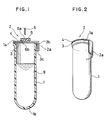
- a tubular member 1 of the tube has an open end 1a, which is closed by a closure member 2 of film-seal type as closure means.
- the closure member 2 has a two-layer structure consisting of an inner film-like sealing member 3 and an outer separable member 4.
- the film-like sealing member 3 is bonded to the open end 1a of the tubular member 1 with closed bottom 1b.
- the closure member 2 has an edge extension extending beyond the open end 1a and having an integral tab 2a extending in a bent fashion along the periphery of the tubular member 1.
- the tubular member 1 has an increased thickness at the open end 1a for provide for an increased bonding area.
- the separable member 4 is laminated on the outer or upper surface of the sealing member 3 so that the sealing member 3 can remain on the open end 1a in a closing state even after the separable member 4 is separated.
- the adhesive strength between the sealing member 3 and separable member 4 is lower than the adhesive strength between the sealing member 3 and open end 1a of the tubular member 1.
- a disk-like seal member 6 is bonded to the center of the outer surface of the separable member 4.
- the seal member 6 is made of rubber and can seal a pierced portion again after removal of a piercing needle 5. It has a central recess 6a formed on the outer side and an annular groove 6b formed on the lower side and coaxial with the recess 6a.
- the tab 2a when taking out liquid in the liquid collecting tube, the tab 2a is pulled with a hand away from the periphery of the tubular member 1. Since the adhesive strength between the sealing member 3 and separable member 4 is lower than the adhesive strength between the sealing member 3 and open end 1a and also the sealing member 3 has a lower mechanical strength than the adhesive strength between the sealing member 3 and separable member 4, by pulling the tab 2a an extension 3c of the sealing member 3 made overlapped over the tab 2a is broken apart along a bent line 2b of the tab and separated together with the separable member 4 as shown by arrow in Fig. 3. The remaining sealing member 3 on the open end 1a keeps the end 1a closed. Thus, attached liquid 7 attached to the lower or inner surface of the sealing member 3 is never scattered to the outside of the tube.
- the piercing needle 5 When collecting blood 9 as liquid to be collected in the liquid collecting tube, the piercing needle 5 is inserted into the tubular member 1 by piercing the seal member 6, separable member 4 and sealing member 3.
- the trace of pierce remains as small hole in the sealing member 3 when taking out the collected blood 9.
- a pipette 9 or like take-out tool thus can be smoothly inserted into the tubular member 1 without possibility of greatly breaking the sealing member 3 by inserting the pipette 8 or the like with the pierce trace as guide.
- the operation of inserting the pipette 8 or the like may be much facilitated by providing the sealing member 3 at a substantially central position thereof, i.e., the position of the pierce trace of the piercing needle 5, with a lightly greater notch 10, as shown in Fig. 4.
- the notch 10 is desirably comparatively small lest the contained liquid 9 such as blood should leak to the outside.
- the notch 10 need not be provided if the sealing member 3 is made from a material, which is thin and can be readily broken by the take-out tool 8.
- the sealing member 3 may have a thickness of 3 to 1,000 ⁇ m, preferably 5 to 20 ⁇ m.
- the closure member 2 has a two-layer structure having the sealing member 3 and separable member 4, its more detailed structure is shown in Fig. 5.
- the separable member 4 having a reinforcement layer 4a of polyethylene telephthalate (PET) and a gas barrier layer 4b formed by vacuum deposition of aluminum on the layer 4a
- the sealing member 3 has a layer 3a formed by coating a solution containing polyethylene telephthalate on a gas barrier layer and by causing evaporation of the solvent and an adhesive layer 3b formed by coating denatured polyethylene on the layer 3a.
- the sealing member 2 may be press stamped together with the tab 2a, and it may be mounted on the tubular member 1 by fusion bonding the adhesive layer 3b to the open end 1a of the tubular member 1.
- the reinforcement layer 4a serves to reinforce the gas barrier layer 4b and sealing member 3, and it may be made of nylon, polycarbonate, etc. as well as polyethylene telephthalate. While the gas barrier layer 4b is formed by depositing aluminum, this is by no means limitative; for instance, it is possible to select any material having adequate gas barrier property, which is particularly effective when maintaining the tube inside under a reduced pressure particularly for securing a predetermined quantity of collected liquid, this permitting predetermined gas tightness to be ensured.
- the seal member 6 serves to re-seal a portion of the closure member with a pierce trace of the piercing needle for preventing leakage of the collected liquid to the outside of the tube, or more correctly for isolating the collected liquid from the outside.
- layer 3a and adhesive layer 3b noted above are by no means limitative.
- the tubular member 1 with bottom as shown in Fig. 1 was formed by injection molding polyester resin (provided by Mitsui PET Co., Ltd. under a trade name "J025/B010" with a weight ratio of 7 : 3).
- the inner diameter of the open end 1a of the tubular member 1 was set to 13.4 mm, the taper to 15/1,000, and the thickness to 2.0 mm at the open end 1a (with an outer diameter of 17.3 mm at the open end) and to 1.2 mm for the rest.
- the seal member 6 used was one having the shape as shown in Fig. 1. It was made of natural rubber. Its diameter was set to 7.0 mm, its thickness to 2.0 mm, the diameter and depth of its recess 6a to 3.0 mm and 0.8 mm, respectively, and the diameter, depth and width of its annular groove 6b to 6.0 mm, 0.2 mm and 0.5 mm, respectively. This seal member 6 is bonded to the center of the outer surface of the separable member 4 by dropping 2 mg of an instant adhesive.
- Polypropyrene glycol was coated by dipping on the inner surfaces of the tubular member 1 and sealing member 3.
- this tubular member 1 was accommodated 1 mg of a blood solidification promoter containing glass particles (with average size of 2 ⁇ m) and polyvinyl pyrolidon (with weight ratio of glass particles and polyvinyl pyrolidon being 5 : 1).
- the tube inside was then held under a reduced pressure (325 mmHg), and then the tube was sterilized by irradiation with 1.0 Mrad of ⁇ -rays, thus, obtaining an experimental liquid collecting tube.
- a separate experimental liquid collecting tube was obtained by accommodating 3.0 mm of particles of EDTA-2K in lieu of the glass particles and polyvinyl pyrolidon noted above and holding the tube inside under a reduced pressure of 585 mmHg.
- the liquid collecting tube according to the invention by pulling apart the closure member 2 for taking out liquid only the separable member 4 is separated, leaving the film-like sealing member 3, which can be pierced by the take-out tool 8, on the open end 1a of the tubular member 1 to keep the open end 1a closed.
- the possibility of scattering of attached liquid to the closure member when removing the closure member 2 as in the prior art can be preclused, thus permitting prevention of pollution.
- the sealing member 3 can be readily pierced by a pipette or like liquid take-out tool, thus permitting smooth take-out operation. It is thus possible to provide a liquid collecting tube, which is simple in construction and can be sued safely.
Landscapes
- Health & Medical Sciences (AREA)
- Life Sciences & Earth Sciences (AREA)
- Engineering & Computer Science (AREA)
- Hematology (AREA)
- General Health & Medical Sciences (AREA)
- Animal Behavior & Ethology (AREA)
- Public Health (AREA)
- Biomedical Technology (AREA)
- Heart & Thoracic Surgery (AREA)
- Medical Informatics (AREA)
- Molecular Biology (AREA)
- Surgery (AREA)
- Biophysics (AREA)
- Physics & Mathematics (AREA)
- Pathology (AREA)
- Veterinary Medicine (AREA)
- Manufacturing & Machinery (AREA)
- Chemical & Material Sciences (AREA)
- Analytical Chemistry (AREA)
- Clinical Laboratory Science (AREA)
- Chemical Kinetics & Catalysis (AREA)
- Measurement Of The Respiration, Hearing Ability, Form, And Blood Characteristics Of Living Organisms (AREA)
- Investigating Or Analysing Biological Materials (AREA)
- Sampling And Sample Adjustment (AREA)
Applications Claiming Priority (2)
| Application Number | Priority Date | Filing Date | Title |
|---|---|---|---|
| JP317754/88 | 1988-12-16 | ||
| JP63317754A JPH02162229A (ja) | 1988-12-16 | 1988-12-16 | 採液管 |
Publications (3)
| Publication Number | Publication Date |
|---|---|
| EP0373667A2 true EP0373667A2 (fr) | 1990-06-20 |
| EP0373667A3 EP0373667A3 (fr) | 1991-03-13 |
| EP0373667B1 EP0373667B1 (fr) | 1994-02-23 |
Family
ID=18091665
Family Applications (1)
| Application Number | Title | Priority Date | Filing Date |
|---|---|---|---|
| EP89123212A Expired - Lifetime EP0373667B1 (fr) | 1988-12-16 | 1989-12-15 | Tube collecteur pour liquides |
Country Status (11)
| Country | Link |
|---|---|
| US (1) | US5326534A (fr) |
| EP (1) | EP0373667B1 (fr) |
| JP (1) | JPH02162229A (fr) |
| AU (1) | AU616828B2 (fr) |
| CA (1) | CA2005732C (fr) |
| DE (1) | DE68913282T2 (fr) |
| DK (1) | DK637789A (fr) |
| ES (1) | ES2049309T3 (fr) |
| FI (1) | FI896022A7 (fr) |
| NO (1) | NO895057L (fr) |
| ZA (1) | ZA899614B (fr) |
Cited By (3)
| Publication number | Priority date | Publication date | Assignee | Title |
|---|---|---|---|---|
| EP0568036A1 (fr) * | 1992-04-28 | 1993-11-03 | Mitsubishi Kagaku Bio-Clinical Laboratories, Inc. | Machine d'ouverture de récipients avec opercules thermosoudables |
| US5358641A (en) * | 1989-10-27 | 1994-10-25 | Helena Laboratories Corporation | Column analyzer system and improved chromatograph column for use in the system |
| WO2005025750A1 (fr) * | 2003-09-18 | 2005-03-24 | Ecocap's S.R.L. | Bouchon colle ou thermoscelle pour refermeture hermetique de tubes de test pour analyses cliniques |
Families Citing this family (17)
| Publication number | Priority date | Publication date | Assignee | Title |
|---|---|---|---|---|
| US5789251A (en) * | 1994-06-16 | 1998-08-04 | Astle; Thomas W. | Multi-well bioassay tray with evaporation protection and method of use |
| US5888826A (en) * | 1994-06-30 | 1999-03-30 | Dade Behring Inc. | Combination reagent holding and test device |
| NZ286445A (en) * | 1995-05-16 | 1997-12-19 | Ivac Corp | Needleless luer connector: deformable piston occludes bore |
| EP2275821A1 (fr) * | 1995-07-31 | 2011-01-19 | Precision System Science Co., Ltd | Conteneur |
| AU744547B2 (en) * | 1998-03-18 | 2002-02-28 | Sekisui Chemical Co., Ltd. | Plug body for vacuum specimen sampling container, vacuum specimen sampling container, vacuum specimen sampling system, vacuum specimen sampling holder, and thermoplastic elastomer composition for plug body |
| US6716396B1 (en) | 1999-05-14 | 2004-04-06 | Gen-Probe Incorporated | Penetrable cap |
| US6382441B1 (en) * | 2000-03-22 | 2002-05-07 | Becton, Dickinson And Company | Plastic tube and resealable closure having protective collar |
| ATE422965T2 (de) | 2001-03-09 | 2009-03-15 | Gen Probe Inc | Verfahren zum entnehmen von flüssigkeit aus einem behälter mit durchdringbarem verschluss |
| US20050013743A1 (en) * | 2003-07-18 | 2005-01-20 | Edward Francis Farina | I-shaped slit in a lidstock covering an array of aliquot vessels |
| DE102004052082A1 (de) * | 2004-10-26 | 2006-04-27 | Dade Behring Marburg Gmbh | Durchstoßbare, flexible Vorrichtung zur Abdeckung von Flüssigkeitsbehältnissen |
| ITPD20050372A1 (it) * | 2005-12-19 | 2007-06-20 | Vacutest Kima Srl | Provetta in plastica per effettuare prelievi di sangue |
| US8387811B2 (en) * | 2007-04-16 | 2013-03-05 | Bd Diagnostics | Pierceable cap having piercing extensions |
| US8387810B2 (en) * | 2007-04-16 | 2013-03-05 | Becton, Dickinson And Company | Pierceable cap having piercing extensions for a sample container |
| EP2080708A1 (fr) * | 2008-01-15 | 2009-07-22 | InBev S.A. | Fermeture |
| JP5959897B2 (ja) | 2012-03-30 | 2016-08-02 | シスメックス株式会社 | 血液分析装置用の洗浄液入り容器 |
| EP3034169A1 (fr) * | 2014-12-15 | 2016-06-22 | Euroimmun Medizinische Labordiagnostika AG | Réservoir pour liquides |
| CN111686833B (zh) * | 2020-07-01 | 2025-05-30 | 桂林优利特医疗电子有限公司 | 一种免开盖试管结构 |
Family Cites Families (16)
| Publication number | Priority date | Publication date | Assignee | Title |
|---|---|---|---|---|
| US2436291A (en) * | 1946-06-25 | 1948-02-17 | Lewis H Daniel | Self-sealing closure for containers |
| FR2120348A5 (fr) * | 1970-12-30 | 1972-08-18 | Jintan Terumo Co | |
| US3823840A (en) * | 1972-08-04 | 1974-07-16 | Silver J | Prepunctured closure |
| US3888377A (en) * | 1973-05-30 | 1975-06-10 | Reinhard Stadler | Closure cap for an infusion flask |
| US4187893A (en) * | 1978-07-19 | 1980-02-12 | Abbott Laboratories | Combined additive and administration port for a container |
| US4266687A (en) * | 1980-02-29 | 1981-05-12 | U.S. Clinical Products, Inc. | Sealing cover and method for resealing an intravenous container |
| AT368389B (de) * | 1981-02-27 | 1982-10-11 | C A Greiner Und Soehne Ges M B | Mit einer dichtung verschlossenes, evakuierbares blutprobenroehrchen |
| JPS5886173A (ja) * | 1981-11-16 | 1983-05-23 | 東洋製罐株式会社 | 輸液用容器の栓及びその製造方法 |
| FR2529531A1 (fr) * | 1982-07-01 | 1984-01-06 | Lyonnaise Bouchage | Moyens de bouchage d'un recipient du type comportant un opercule en feuille d'aluminium ou similaire, fixe par collage ou soudage sur l'entourage de l'orifice du recipient |
| SE8400288L (sv) * | 1984-01-20 | 1985-07-21 | Anders Edvard Trell | Anordning for tagning och settning av blodsenkeprov |
| AT380392B (de) * | 1985-01-24 | 1986-05-12 | C A Greiner & S Hne Ges M B H | Blutprobenr!hrchen |
| US4598834A (en) * | 1985-02-06 | 1986-07-08 | U.S. Clinical Products, Inc. | Flexible sterile closure system for a container with a side injection port |
| US4657152A (en) * | 1985-11-27 | 1987-04-14 | Baxter Travenol Laboratories, Inc. | Thermoplastic foam fitment |
| WO1988004154A1 (fr) * | 1986-12-11 | 1988-06-16 | Terumo Kabushiki Kaisha | Tube de prelevement de sang |
| IT1223535B (it) * | 1987-12-18 | 1990-09-19 | Instrumentation Lab Spa | Perfezionamenti ai dispositivi monouso per prelievo e contenimento di campioni di sangue |
| JPH02212768A (ja) * | 1989-02-13 | 1990-08-23 | Terumo Corp | 採液管 |
-
1988
- 1988-12-16 JP JP63317754A patent/JPH02162229A/ja active Pending
-
1989
- 1989-12-15 EP EP89123212A patent/EP0373667B1/fr not_active Expired - Lifetime
- 1989-12-15 ZA ZA899614A patent/ZA899614B/xx unknown
- 1989-12-15 FI FI896022A patent/FI896022A7/fi not_active Application Discontinuation
- 1989-12-15 ES ES89123212T patent/ES2049309T3/es not_active Expired - Lifetime
- 1989-12-15 NO NO89895057A patent/NO895057L/no unknown
- 1989-12-15 CA CA002005732A patent/CA2005732C/fr not_active Expired - Fee Related
- 1989-12-15 DE DE68913282T patent/DE68913282T2/de not_active Expired - Fee Related
- 1989-12-15 AU AU46900/89A patent/AU616828B2/en not_active Ceased
- 1989-12-15 DK DK637789A patent/DK637789A/da not_active Application Discontinuation
-
1992
- 1992-08-07 US US07/927,193 patent/US5326534A/en not_active Expired - Fee Related
Cited By (6)
| Publication number | Priority date | Publication date | Assignee | Title |
|---|---|---|---|---|
| US5358641A (en) * | 1989-10-27 | 1994-10-25 | Helena Laboratories Corporation | Column analyzer system and improved chromatograph column for use in the system |
| US5589063A (en) * | 1989-10-27 | 1996-12-31 | Helena Laboratories Corporation | Column analyzer system and improved chromatograph column for use in the system |
| US5595664A (en) * | 1989-10-27 | 1997-01-21 | Helena Laboratories Corporation | Column analyzer system and improved chromatograph column for use in the system |
| EP0568036A1 (fr) * | 1992-04-28 | 1993-11-03 | Mitsubishi Kagaku Bio-Clinical Laboratories, Inc. | Machine d'ouverture de récipients avec opercules thermosoudables |
| US5429022A (en) * | 1992-04-28 | 1995-07-04 | Mitsubishi Yuka Bio-Clinical Laboratories, Inc. | Opening machine for film seal cap |
| WO2005025750A1 (fr) * | 2003-09-18 | 2005-03-24 | Ecocap's S.R.L. | Bouchon colle ou thermoscelle pour refermeture hermetique de tubes de test pour analyses cliniques |
Also Published As
| Publication number | Publication date |
|---|---|
| ES2049309T3 (es) | 1994-04-16 |
| DK637789D0 (da) | 1989-12-15 |
| FI896022A7 (fi) | 1990-06-17 |
| NO895057L (no) | 1990-06-18 |
| AU4690089A (en) | 1990-07-19 |
| US5326534A (en) | 1994-07-05 |
| CA2005732A1 (fr) | 1990-06-16 |
| JPH02162229A (ja) | 1990-06-21 |
| EP0373667A3 (fr) | 1991-03-13 |
| NO895057D0 (no) | 1989-12-15 |
| ZA899614B (en) | 1990-09-26 |
| DE68913282D1 (de) | 1994-03-31 |
| EP0373667B1 (fr) | 1994-02-23 |
| FI896022A0 (fi) | 1989-12-15 |
| CA2005732C (fr) | 1995-05-23 |
| DK637789A (da) | 1990-06-17 |
| AU616828B2 (en) | 1991-11-07 |
| DE68913282T2 (de) | 1994-07-07 |
Similar Documents
| Publication | Publication Date | Title |
|---|---|---|
| US5326534A (en) | Liquid collection tube | |
| KR900009014B1 (ko) | 채혈관 | |
| EP0867378B1 (fr) | Dispositif pour collecter du sang ou d'autres fluides corporels | |
| US6382441B1 (en) | Plastic tube and resealable closure having protective collar | |
| JP4494452B2 (ja) | 液体試料用容器蓋 | |
| US5019243A (en) | Apparatus for collecting blood | |
| JP2688566B2 (ja) | 医療検査等に用いる検査対象物の収納具 | |
| EP0383262A2 (fr) | Tube de collection pour liquides | |
| EP0341587B1 (fr) | Appareil pour recueillir du sang | |
| EP0922643A1 (fr) | Couvercle | |
| JP2001057969A (ja) | 採集アセンブリ | |
| US9999888B2 (en) | Specimen container for urine and other liquids | |
| EP0414179A1 (fr) | Tube d'essai pour des échantillons de liquides | |
| EP1174085B1 (fr) | Dispositif pour collecter du sang ou d'autres fluides corporels | |
| JPH0316134B2 (fr) | ||
| JP2553935Y2 (ja) | 喀痰検査用集細胞器 | |
| JPH0618945U (ja) | 減圧採血管 | |
| KR102961539B1 (ko) | 의료 샘플 이송 및 처리용 재폐쇄 격막 캡 | |
| JPH02174835A (ja) | 減圧採血管 | |
| AU746794B2 (en) | Assembly for collecting blood or other body fluids | |
| WO1989000830A1 (fr) | Tube collecteur de sang | |
| MXPA98001956A (en) | Set to collect blood or other fluids corpora | |
| JPH0544105U (ja) | 減圧採血管 | |
| JPH02154743A (ja) | 採液管 |
Legal Events
| Date | Code | Title | Description |
|---|---|---|---|
| PUAI | Public reference made under article 153(3) epc to a published international application that has entered the european phase |
Free format text: ORIGINAL CODE: 0009012 |
|
| 17P | Request for examination filed |
Effective date: 19891215 |
|
| AK | Designated contracting states |
Kind code of ref document: A2 Designated state(s): BE CH DE ES FR GB IT LI NL SE |
|
| PUAL | Search report despatched |
Free format text: ORIGINAL CODE: 0009013 |
|
| AK | Designated contracting states |
Kind code of ref document: A3 Designated state(s): BE CH DE ES FR GB IT LI NL SE |
|
| 17Q | First examination report despatched |
Effective date: 19920110 |
|
| GRAA | (expected) grant |
Free format text: ORIGINAL CODE: 0009210 |
|
| AK | Designated contracting states |
Kind code of ref document: B1 Designated state(s): BE CH DE ES FR GB IT LI NL SE |
|
| ET | Fr: translation filed | ||
| REF | Corresponds to: |
Ref document number: 68913282 Country of ref document: DE Date of ref document: 19940331 |
|
| ITF | It: translation for a ep patent filed | ||
| REG | Reference to a national code |
Ref country code: ES Ref legal event code: FG2A Ref document number: 2049309 Country of ref document: ES Kind code of ref document: T3 |
|
| PGFP | Annual fee paid to national office [announced via postgrant information from national office to epo] |
Ref country code: GB Payment date: 19941206 Year of fee payment: 6 |
|
| PGFP | Annual fee paid to national office [announced via postgrant information from national office to epo] |
Ref country code: DE Payment date: 19941208 Year of fee payment: 6 |
|
| PGFP | Annual fee paid to national office [announced via postgrant information from national office to epo] |
Ref country code: FR Payment date: 19941209 Year of fee payment: 6 |
|
| PGFP | Annual fee paid to national office [announced via postgrant information from national office to epo] |
Ref country code: CH Payment date: 19941214 Year of fee payment: 6 |
|
| PGFP | Annual fee paid to national office [announced via postgrant information from national office to epo] |
Ref country code: SE Payment date: 19941215 Year of fee payment: 6 |
|
| PGFP | Annual fee paid to national office [announced via postgrant information from national office to epo] |
Ref country code: ES Payment date: 19941223 Year of fee payment: 6 |
|
| PLBE | No opposition filed within time limit |
Free format text: ORIGINAL CODE: 0009261 |
|
| PGFP | Annual fee paid to national office [announced via postgrant information from national office to epo] |
Ref country code: NL Payment date: 19941231 Year of fee payment: 6 |
|
| EAL | Se: european patent in force in sweden |
Ref document number: 89123212.6 |
|
| PGFP | Annual fee paid to national office [announced via postgrant information from national office to epo] |
Ref country code: BE Payment date: 19950207 Year of fee payment: 6 |
|
| 26N | No opposition filed | ||
| PG25 | Lapsed in a contracting state [announced via postgrant information from national office to epo] |
Ref country code: GB Effective date: 19951215 |
|
| PG25 | Lapsed in a contracting state [announced via postgrant information from national office to epo] |
Ref country code: SE Effective date: 19951216 Ref country code: ES Free format text: LAPSE BECAUSE OF EXPIRATION OF PROTECTION Effective date: 19951216 |
|
| PG25 | Lapsed in a contracting state [announced via postgrant information from national office to epo] |
Ref country code: LI Effective date: 19951231 Ref country code: CH Effective date: 19951231 Ref country code: BE Effective date: 19951231 |
|
| BERE | Be: lapsed |
Owner name: TERUMO K.K. Effective date: 19951231 |
|
| PG25 | Lapsed in a contracting state [announced via postgrant information from national office to epo] |
Ref country code: NL Effective date: 19960701 |
|
| GBPC | Gb: european patent ceased through non-payment of renewal fee |
Effective date: 19951215 |
|
| REG | Reference to a national code |
Ref country code: CH Ref legal event code: PL |
|
| PG25 | Lapsed in a contracting state [announced via postgrant information from national office to epo] |
Ref country code: FR Effective date: 19960830 |
|
| NLV4 | Nl: lapsed or anulled due to non-payment of the annual fee |
Effective date: 19960701 |
|
| PG25 | Lapsed in a contracting state [announced via postgrant information from national office to epo] |
Ref country code: DE Effective date: 19960903 |
|
| REG | Reference to a national code |
Ref country code: FR Ref legal event code: ST |
|
| REG | Reference to a national code |
Ref country code: ES Ref legal event code: FD2A Effective date: 20010201 |
|
| PG25 | Lapsed in a contracting state [announced via postgrant information from national office to epo] |
Ref country code: IT Free format text: LAPSE BECAUSE OF NON-PAYMENT OF DUE FEES;WARNING: LAPSES OF ITALIAN PATENTS WITH EFFECTIVE DATE BEFORE 2007 MAY HAVE OCCURRED AT ANY TIME BEFORE 2007. THE CORRECT EFFECTIVE DATE MAY BE DIFFERENT FROM THE ONE RECORDED. Effective date: 20051215 |