EP0373738A2 - Gerät für ultra-schnelle Kühlung auf kryogene Temperaturen - Google Patents
Gerät für ultra-schnelle Kühlung auf kryogene Temperaturen Download PDFInfo
- Publication number
- EP0373738A2 EP0373738A2 EP89303113A EP89303113A EP0373738A2 EP 0373738 A2 EP0373738 A2 EP 0373738A2 EP 89303113 A EP89303113 A EP 89303113A EP 89303113 A EP89303113 A EP 89303113A EP 0373738 A2 EP0373738 A2 EP 0373738A2
- Authority
- EP
- European Patent Office
- Prior art keywords
- cryo
- vacuum
- chamber
- slam
- cryogenic
- Prior art date
- Legal status (The legal status is an assumption and is not a legal conclusion. Google has not performed a legal analysis and makes no representation as to the accuracy of the status listed.)
- Withdrawn
Links
Images




Classifications
-
- B—PERFORMING OPERATIONS; TRANSPORTING
- B01—PHYSICAL OR CHEMICAL PROCESSES OR APPARATUS IN GENERAL
- B01D—SEPARATION
- B01D8/00—Cold traps; Cold baffles
-
- F—MECHANICAL ENGINEERING; LIGHTING; HEATING; WEAPONS; BLASTING
- F25—REFRIGERATION OR COOLING; COMBINED HEATING AND REFRIGERATION SYSTEMS; HEAT PUMP SYSTEMS; MANUFACTURE OR STORAGE OF ICE; LIQUEFACTION SOLIDIFICATION OF GASES
- F25D—REFRIGERATORS; COLD ROOMS; ICE-BOXES; COOLING OR FREEZING APPARATUS NOT OTHERWISE PROVIDED FOR
- F25D19/00—Arrangement or mounting of refrigeration units with respect to devices or objects to be refrigerated, e.g. infrared detectors
- F25D19/006—Thermal coupling structure or interface
-
- G—PHYSICS
- G01—MEASURING; TESTING
- G01N—INVESTIGATING OR ANALYSING MATERIALS BY DETERMINING THEIR CHEMICAL OR PHYSICAL PROPERTIES
- G01N1/00—Sampling; Preparing specimens for investigation
- G01N1/28—Preparing specimens for investigation including physical details of (bio-)chemical methods covered elsewhere, e.g. G01N33/50, C12Q
- G01N1/42—Low-temperature sample treatment, e.g. cryofixation
-
- F—MECHANICAL ENGINEERING; LIGHTING; HEATING; WEAPONS; BLASTING
- F25—REFRIGERATION OR COOLING; COMBINED HEATING AND REFRIGERATION SYSTEMS; HEAT PUMP SYSTEMS; MANUFACTURE OR STORAGE OF ICE; LIQUEFACTION SOLIDIFICATION OF GASES
- F25D—REFRIGERATORS; COLD ROOMS; ICE-BOXES; COOLING OR FREEZING APPARATUS NOT OTHERWISE PROVIDED FOR
- F25D2400/00—General features of, or devices for refrigerators, cold rooms, ice-boxes, or for cooling or freezing apparatus not covered by any other subclass
- F25D2400/30—Quick freezing
Definitions
- This invention relates to cryo-fixation apparatus and method for the ultrarapid cooling of biological samples.
- Ultrarapid cooling is a preparatory step to the cryo preparation of biological samples in apparatus such as that described in commonly assigned U.S. Patent Nos. 4,510,169 and 4,567,847 issued to John G. Linner and commonly referred to as “The Linner Process” or “The Linner Apparatus”. It is well known in the medical arts that to examine biological samples and determine the cellular structure and function thereof, the samples must be "fixed” with minimal alteration of ultrastructural integrity prior to the application of nearly all analytical methodologies.
- the apparatus of this invention can be used to ultrarapidly cool biological samples without the formation of resolvable ice crystals so that the ultra-structural integrity of the sample is not altered.
- samples of a biological material that are more than a few microns in thickness the ice crystals will usually range in size from amorphous at the leading edge to hexagonal in the interior of the tissue. There is a gradient effect during the formation of ice crystals.
- biological material used throughout this disclosure to refer to samples that can be ultrarapidly cooled by the method and apparatus of this invention.
- the terms are used interchangeably and are not intended as a limitation on the functional capability of the method or apparatus disclosed herein.
- the terms should be understood to include small tissue samples appropriate for microscopic examination and larger tissue masses such as corneas which are appropriate for transplantation.
- the terms should be understood to include any material composed of one or more cells, either individual or in complex with any matrix or in association with any chemical; and to include any biological or organic material and any cellular sub-portion, product or by-product thereof.
- tissue tissue specimen(s)
- tissue sample(s) tissue sample(s)
- the method and apparatus of this invention are preferably used as a preliminary step in the cryo-preparation of biological samples for ultrastructural analysis, i.e. electron microscopy, it should be understood that this is not intended as a limitation on the utility of the apparatus and method of this invention.
- the ultrarapid cooling method and apparatus of this invention have demonstrated utility in any area in which the ultrastructure of cellular components is desirably maintained in an unaltered state. Examples of such utility include, but are not limited to, electron microscopy, tissue preservation, tissue and organ transplants and various analytical and diagnostic methodologies. Therefore, although the method and apparatus of this invention are typically described in relationship to electron microscopy this should be understood not to be a limiting factor on the utility of the invention.
- the primary thrust of this application is in the preparation of tissue samples for analysis by current magnification apparatus, the invention is not intended to be so limited. More specifically, the "preparation" of tissue should be understood to refer to preparation of tissue for analysis as well as the cryofixation of tissue in anticipation of transplantation, modification, in vitro or in vivo cellular growth, fertilization, animated suspension or the more typical resin impregnation, setting, infiltration and analysis.
- the apparatus of this invention can be used to prepare tissue for any medical or analytical procedure without the ultrastructural damage previously thought to be inevitable in cryopreparation.
- the apparatus of this invention is to be distinguished from contemporary freeze-drying apparatus.
- Freeze-drying is a technique which is well known in the art together with the equipment necessary to implement such freeze-drying. See, for example, U. S. Patent 4,232,453.
- liquid nitrogen is used as a cooling medium, the tissue or sample itself does not attain such temperature.
- Freeze-drying normally contemplates sample temperatures of -50°C to -80°C.
- the ultrarapid cooling step of the cryopreparation process of the Linner ProcessTM and apparatus contemplate sample temperatures of -175°C or colder. Therefore, for purposes of this application the terms "cryopreparation” and “cryofixation” are used in distinction to conventional "freezing" technology.
- tissue preparation methods and the apparatus necessary to prepare tissue samples be equally advanced as the analytical tools, i.e., electron microscopes, which are being used to analyze the samples.
- the advanced microscopes cannot be used to full advantage by the morphologist or other tissue examiner.
- cryopreparation methods and apparatus develop concurrently with other medical technology, i.e., surgical transplant techniques, bio-engineering and biogenetics.
- cryopreparation is an essential intermediate step in evolving processes using or analyzing cells or tissue. If cryo-preparation apparatus does not evolve then the thrust of medical technology into unexplained and unexplored medical arts will be blunted.
- the apparatus of this invention represents the cryopreparation breakthrough that will permit research into the use and preparation of biological tissue to keep pace with other advances in medical technology.
- the ultrarapid cooling apparatus of this invention provides the mechanism for eliminating the problems associated with available cryofixation apparatus.
- cryofixation results in a near-instantaneous arrest of cellular metabolism. There is also a stabilization and retention of soluble cell constituents through elimination of solvent contact with the sample.
- freeze-drying technology inherently possesses a number of disadvantages relevant to tissue preparation methodologies.
- the primary disadvantage in currently available freezing techniques and apparatus is the inherent formation of ice crystals.
- the formation of ice crystals destroys the ultrastructural integrity of the tissue sample being reviewed. The image is distorted and the cytoplasm becomes reticulated.
- the formation of ice crystals in the sample can also result in a change in pH within microcompartments of the tissue (eutectic formation) which possibly can result in abnormal tertiary conformation of macromolecules.
- proteins will denature and precipitate.
- the term “vitrified” or “vitrification” refers to the cryopreparation of tissue samples without the formation of resolvable ice crystals within the cellular structure. It has been postulated that regardless of the rate of cooling, ice crystals may still be formed, but as the cooling rates increase the size of the intracellular ice crystals decreases. The small size or absence of ice crystals at high freeze rates is of course a substantial advantage in morphology retention as this results in minimal artifact creation and minimal ultrastructural alteration or damage during tissue dehydration.
- the apparatus of this invention provides the ultrarapid cooling of one or more tissue samples to the vitreous phase in less than one second.
- the ultrarapid cooling according to the present invention is followed by dehydration of the tissue sample while in the state of reduced partial pressure of water vapor without substantial ultrastructural damage to the tissue cells.
- the criteria by which the techniques for rapid supercooling have been judged was not the cooling rate of the system but simply the temperature of the environment in which the tissue was frozen.
- rapid supercooling has been applied to any system in which the supercooling agent has a temperature of -150° C or below.
- the effectiveness of a cooling system is dependent upon the rate at which heat is removed from the sample. Heat transfer is dependent not only on the temperature of the freezing system but also on its physical and thermal characteristics, as well as the size and thermal characteristics of the tissue.
- the most commonly used technique for rapid supercooling is to immerse or "quench" the sample in a fluid cooling bath.
- the most commonly used fluids for quenching are liquid nitrogen, isopentane, propane and fluorocarbons such as Freon 12 and Freon 22.
- liquid nitrogen is generally regarded as an ideal quenching fluid due to its low temperature (-196°C)
- there are inherent disadvantages in the use of liquid nitrogen due to the occurrence of tissue surface film boiling caused at least in part by the low heat of vaporization of liquid nitrogen. Film boiling is a characteristic of liquid nitrogen that inhibits the heat transfer rate by actually insulating the sample.
- An alternative method for rapid supercooling is applying the tissue sample to the polished surface of a cryogenically cooled material such as the surface of a chilled metal block. This typically involves opposing the tissue sample to a polished flat metal surface by pressing it firmly against the surface of the metal. Silver and copper are typically used as the polished metal blocks. This method is designed to take advantage of the high thermal conductivities and heat capacities of these metals when cooled to liquid nitrogen or liquid helium temperatures.
- the critical step in chilling on the surface of a metal is making firm contact with the dry, chilled metal surface with no rotational, translational or rebounding motion.
- Certain commercially available apparatus having known utility in the medical arts address and provide "bounce-free" freezing. Credit for the development of this apparatus is generally accorded to Dr. Alan Boyne of the University of Maryland School of Medicine.
- the Boyne apparatus and method included one or more copper bars partially submerged in a container filled with liquid nitrogen at -196°C.
- the end of the copper bar was a mirror-finished smooth cryogenic surface, and the thermal conductivity of copper enabled the surface to be cooled.
- a tissue sample was then dropped by gravity against the surface.
- the Boyne sample delivery assembly employed a weight dampening system utilizing glycerol to absorb the impact. Each copper bar must be cleaned after slamming a sample.
- the drawbacks of the Boyne apparatus included problems of hydrocarbon contamination and condensation on the cryogenic surface, inability to eliminate all bounce or vibration between the sample and surface, undesirable precooling of the sample with escaping nitrogen gas, and delays for cleaning and regenerating the cryogenic surface of the copper bars between each sequential sample.
- the Boyne method and apparatus thus could not reliably provide tissue samples with good ice crystal-free zones nor was it capable of properly vitrifying the samples beyond a depth of 10 to 15 microns.
- Escaig Further development of freezing tissue samples against a metal block has been credited to Jacques Escaig of Paris, France.
- the method and apparatus of Escaig is described in "Control of Different Parameters For Optimal Freezing Conditions", Jacques Escaig, published in Science of Biological Specimen Preparation , at pp. 117-122 (1984).
- the Escaig apparatus also is disclosed in Swiss Patent No. 614,532, French Patent No. 2,337,878 and German Patent No. 2,700,196.
- Escaig provided several significant features not shown in earlier methods or devices for vitrifying tissue against a metal block.
- the Escaig method and apparatus cool a copper block with liquid helium, rather than liquid nitrogen, in order to increase the cooling rate of a tissue sample or specimen.
- Escaig disclosed that the average thickness of ice crystal-free zones in the tissue sample were much larger when the copper block was cooled by liquid helium rather than liquid nitrogen. Additionally, Escaig pointed out that the factors influencing the freezing process, independent of the tissue sample itself, are thermal contact between the specimen and metal block, condition of the block surface, specimen slipping, sample holder bounce and sample holder contact strength. Escaig obtained some control of these factors by utilizing a vacuum pump to keep the metal block under vacuum of 1 x 10 ⁇ 3 mbar until just before slamming the specimen against the block, in order to reduce contamination on the block surface. Escaig also utilized an electromagnet to bring the specimen in contact with the block in order to improve mechanical contact between the specimen and the block.
- a copper block is enclosed in a vacuum chamber.
- the chamber is then evacuated to approximately 1 x 10 ⁇ 3 mbar with an external vacuum pump system.
- Escaig employed an external nonreusable cryogen source--liquid helium pumped from a reservoir--to cool the copper block.
- the liquid helium is transmitted to a passage adjacent to the block through a conduit in the vacuum chamber.
- Escaig used an electropneumatic system to open a stem insert in the liquid helium passage for releasing cold helium gas for several seconds into the vacuum chamber itself.
- the cold helium gas admitted into the vacuum chamber is obtained from vaporization of the liquid helium which was used to cool the metal block.
- the cold helium gas raises the pressure inside the vacuum chamber.
- a shutter providing access to the vacuum chamber is spring biased to open the chamber and activate downward movement of a sample delivery assembly, which plunges or slams the tissue sample through the shutter opening and against the block. Opening of the shutter also triggers closing of the stem insert to stop the release of cold helium gas into the chamber.
- Escaig used cold helium gas to bring the vacuum chamber up to atmospheric pressure
- a tissue sample precools for approximately 15 milliseconds as it descends through a layer of cold helium gas at atmospheric pressure prior to plunging or slamming against the metal block.
- the precooling effect of the Escaig device is undesirable due to unwanted effects, such as ice crystal formation, on the physiology of the tissue sample.
- movement of liquid helium and helium gas through the vacuum chamber inevitably resulted in vibration of the metal block, which was undesirable because it reduced or prevented good mechanical contact between the specimen and block.
- Escaig's use of nonreusable liquid helium to cool the block further has proved to be expensive, somewhat unsafe and cumbersome due to the necessity of recooling the entire liquid helium system between each tissue sample.
- the end result was extremely slow turnover time for regenerating the copper block between each sample.
- cleaning the block in the Escaig apparatus proved difficult because of condensation on the block forming after a sample was slammed against the block. To remove the condensation, pressurized nitrogen gas and hot air could be applied against the block.
- removal of the block for repolishing or other cleaning required disassembly of the vacuum chamber itself. Even if the block was not removed, the problems in regenerating the block surface resulted in turnover time between samples which is commercially unacceptable. It was therefore not possible to use the Escaig device if a large number of sequential samples was desired
- the cryopreparation apparatus and method according to the present invention solves the problems inherent in the prior art including the Escaig apparatus and method.
- the present invention addresses the problems in the prior art of slow turnover time between the vitrification of tissue samples, by enabling several samples to be vitrified sequentially.
- the present invention also solves the problems in the prior art caused by undesirable precooling of the tissue sample or specimen before contact with the cryogenic block, cleaning and reheating the cryogenic block between each sample, and removal of the cryogenic block from the apparatus.
- the apparatus and method of the present invention provide for the cryo-slamming (i.e., ultrarapid cooling or vitrification) of tissue samples by slamming or plunging the samples against a chilled cryogenic block.
- the upper portion of the cryogenic block is a highly polished and mirror-finished face or "cryo-slam" surface and the lower portion is a thermally conductive tubular "cryofinger".
- the cryo-slam surface can be removed from the cryofinger for cleaning or replacement with an alternate cryo-slam surface.
- the apparatus contemplates interchanging cryo-slam surfaces to vary surface area, surface shape, and the material composition of the cryo-slam surface.
- the apparatus contemplates chilling of a tissue sample against the mirror-finished smooth cryo-slam surface.
- the cryogenic block is enclosed within an evacuatable chamber.
- an ultra-high hydrocarbon free vacuum chamber may be used.
- ultra-high vacuum and “high vacuum” are used interchangeably although it is recognized that there are technical distinctions.
- the shutter opening to the vacuum chamber and the movement of the tissue sample on the plunger are pneumatically controlled in order to assure precise timing of the shutter and plunger, with a constant rate of descent.
- Noncondensable dry inert gas at room temperature is introduced into the chamber just prior to pneumatically activating the shutter and plunging the sample against the block.
- the introduction of a dry inert gas which is noncondensable at cryogenic temperatures enables the chamber pressure to be raised and the shutter to be opened without undesirable condensation on the cryo-slam surface, or dehydration and precooling of the tissue sample during its downward movement through the shutter opening towards the cryo-slam surface.
- An external source is used to supply the dry inert gas to the chamber.
- the inert gas may be selected from dry nitrogen or a noble gas such as dry helium, and the like.
- the cryo-slam surface may be regenerated rapidly between slamming of successive samples.
- the rapid regeneration is enabled by the use of a heating unit enclosed within the cryofinger.
- the heating unit is activated between samples to heat the cryo-slam surface for cleaning and removing condensation.
- a hydrocarbon-free vacuum must be obtained in the vacuum chamber surrounding the cryogenic block.
- the cryo-slam surface is then cooled with a liquid cryogen system which circulates a coolant such as liquid nitrogen or helium through a cooling jacket.
- the cooling jacket which is enclosed within the vacuum chamber, jackets the thermally conductive cryofinger portion of the cryogenic block.
- the detachable cryo-slam surface is located at the top of the cryofinger which extends below the top of the cooling jacket and is sealed in relation thereto. Dry nitrogen or helium gas is then introduced into the vacuum chamber to bring the pressure to atmospheric before the slamming operation takes place.
- the present invention enables sequential vitrification of tissue samples against the cryo-slam surface without substantial delays for regeneration inherent in the prior art and facilitates rapid recooling.
- cryoprepare tissue specimens without overt disruption or destruction of the morphological characteristics of the ultrastructure of tissue cells.
- the cryo-slamming method and apparatus of the present invention provide for ultrarapid cooling of tissue samples so that the tissue may be dehydrated while maintained in the solid, vitreous phase without creating unnecessary artifacts which restrict interpretation by conventional analytical apparatus.
- the cryo-slamming apparatus and method of the present invention may demonstrate an extraordinary application in the transplanting of corneal tissue.
- Prior to this invention attempts to transplant corneas which involved a necessary freezing or freeze-drying of the corneas after removal from the donor invariably resulted in a clouded cornea upon transplanting.
- the clouding remained for from as little as several days to the life of the transplanted cornea.
- This physical condition of the transplanted cornea was caused by ice crystal formation in the cornea itself and concomitant damage to the stroma.
- Use of the apparatus of this invention has enabled ophthalmologists to cryoprepare corneas and to then transplant those corneas to recipients with virtually negligible clouding or crystal formation.
- the ability to so transplant corneas represents an exceptional advantage to the process of this invention as well as a medical breakthrough in corneal transplant surgery.
- the cryo-slam surface is generally semispherical in shape and adapted to receive a cornea.
- tissue specimens or samples are collected by a variety of means, i.e., surgical extraction, withdrawn blood samples, binders and any of a variety of other techniques which are well known and conventional.
- the particular method of obtaining a sample of a particular biological material is not limiting on the apparatus of this invention.
- the preparation of tissue specimens in the apparatus of this invention is enhanced if the tissue specimens are processed as soon after excising as is possible.
- the preparation of a tissue specimen takes place immediately as it is received.
- the sample cannot be retained in a fixative, i.e., formaldehyde, or another biologically active stabilizing solution, in an attempt to maintain the sample during shipping, storage or other necessary operations. It is also critical that the sample not be routinely frozen or otherwise physically modified prior to preparation according to the method of this invention.
- the sample may later be physically sectioned or otherwise physically prepared for long-term storage in apparatus or use with various currently available commercial analytical apparatus.
- a tissue specimen is prepared for analysis.
- the preferred optimum biological sample for preparation in the apparatus of this invention is a fresh one cubic millimeter biopsy sample.
- This sample must be vitrified as soon as possible.
- vitrifying or vitrification it is intended to make reference to a process which results in cryofixation of the sample which is different from “frozen.”
- the cooling apparatus which is used renders a portion of the sample in the vitreous phase such that soluble and insoluble moieties contained in the tissue sample are not disturbed, translated, or altered nor are they concentrated (as eutectics).
- a vitrified liquid will shatter when undergoing a shear stress, e.g., window glass.
- the vitreous phase involves the conversion of liquid water into an amorphous or "glass” phase. This is accomplished by rapidly supercooling the tissue sample by opposing it "bounce-free” onto the highly polished (mirror-like) contaminate-free cryo-slam surface preferably at between -265°C and -175°C. It is preferred that such rapid supercooling be completed in less than one second.
- the sample may be stored submerged in a liquid nitrogen dewar at -196°C. Once the sample has been dried and embedded properly it may be stored virtually indefinitely without cytoplasmic reticulation or other forms of cellular catabolism which will cause modifications and crystal lattice transitions resulting in undesirable artifacts which render the tissue uninterpretable as analytical data.
- the apparatus for ultrarapid cooling of this invention includes a cryogenic block having an upper cryo-slam surface 20 and a lower cryofinger 25.
- a vacuum source 30 functions to impart a vacuum to the atmosphere surrounding the cryo-slam surface 20.
- the apparatus further includes a source of fluid coolant 40 which functions to bring the cryo-slam surface 20 to cryogenic temperatures.
- a source of noncondensable dry inert gas 50 is also associated with the vacuum chamber 21 to raise the pressure surrounding the cryo-slam surface 20 prior to sample delivery.
- a sample delivery assembly 60 and a shutter assembly 61 are functionally associated with the cryo-slam surface 20 and include means for mounting biological tissue and means for transferring the biological tissue from outside of the chamber enclosing the cryogenic block to inside the chamber and into contact with cryo-slam surface 20.
- a thermocouple (not shown) is embedded at the interface of cryo-slam surface 20 and cryofinger 25. The thermocouple is connected to the wire 84 which leads outside the vacuum chamber 21 through a feedthrough 80. The thermocouple is associated with the cryogenic block to monitor the temperature of cryo-slam surface 20.
- Fig. 1 is a perspective view of a preferred embodiment of the present invention.
- major components of cryo-slamming apparatus include sample delivery assembly 60, vacuum chamber 21, a vacuum source 30, and controls 11.
- the cryo-slamming apparatus is mounted on mounting flange 55 which is fixed to horizontal surface 12 which is enclosed in apparatus housing 15 (Fig. 8).
- the sample delivery assembly 60 comprises a plunger 62 which is slideably mounted in plunger housing 64. At the end of the plunger is a sample holder 70 (Fig. 4).
- Pneumatic conduit 63 is connected to the plunger housing 64.
- the plunger 62 is pneumatically actuated to move the tissue specimen downward against the cryo-slam surface 20 when shutter 65 is pneumatically opened.
- the sample delivery assembly 60 is mounted on base plate 67 which is supported over the vacuum chamber 21 by means of a circular sidewall 68.
- the sample delivery assembly is cooperatively aligned with the vacuum chamber 21 so that it may be actuated pneumatically to move the tissue specimen downward against a cryo-slam surface 20 when the shutter assembly 61 opens access to the vacuum chamber 21.
- the shutter assembly 61 comprises a shutter 65, which is mounted on rod 66 extending from rod housing 75.
- the shutter assembly 61 is pneumatically actuated.
- Pneumatic conduit 76 extends to the rod housing 75.
- the shutter 65 seals the vacuum chamber upper end plate 23, and moves the shutter to open the vacuum chamber when a sample is to be slammed against the cryogenic block.
- the shutter 65 is actuated pneumatically and is movable to open cooperatively with downward movement of plunger 62.
- the pneumatic actuation provides continuous force at a constant rate of descent to the plunger 62, with a functionally effective delay between the time shutter 65 is open until sample application against the cryo-slam surface 20. In most instances the delay will be less than 5 milliseconds.
- the shutter assembly 61 is associated with a flexible shock absorbing mount 77 (Fig. 12) which reduces shock waves to the cryo-slam surface 20 caused by pneumatic actuation of the shutter 65.
- the vacuum chamber 21 includes upper end plate 23, conduit housing 45, and vacuum chamber housing 47. These components are mounted together in sealing relationship and are preferably composed of stainless steel and constructed so they may be vacuum sealed.
- the upper end plate 23 contains an access plate (not shown) which allows easy access to components located within the vacuum chamber 21.
- the access plate is concentric with the shutter opening and is associated with an o-ring seal to prevent leakage under vacuum conditions.
- a cryo-slam surface 20 (Fig. 14) is located within the vacuum chamber 21.
- a source of fluid coolant 40 is provided to cool the cryo-slam surface 20 via cooling inlet conduit 22 which is connected by cooling inlet coupling 38 to the conduit housing flange 45, which in the preferred embodiment is a two-sided conflat flange.
- cooling outlet conduit 28 is connected by cooling outlet coupling 39 to an opposing side of the conduit housing 45.
- the inlet 22 and outlet 28 are used to circulate cooling fluids such as liquid nitrogen or helium to cool the cryogenic block prior to slamming a tissue sample against that surface.
- the vacuum source 30 is connected to the lower end of vacuum chamber housing 47 with a vacuum coupling 34.
- the vacuum source 30 further includes vacuum valves 31 and vacuum conduit 56.
- Vacuum source 30 imparts a high hydrocarbon free vacuum to the vacuum chamber 21.
- the vacuum source 30 includes a combination trap 85 (Fig. 8).
- Fig. 9 shows an exploded view of the combination trap with housing 95 having vacuum line connections 96.
- a molecular sieve 88 is inserted on top of screen 89.
- the fluid coolant reservoir and condensing surface 87 is inserted into housing 95 and sealed with o-ring 94.
- the combination trap upper end plate 86 is secured to the housing 95 with 4 screws 97.
- the fluid coolant reservoir may be filled with a coolant such as liquid nitrogen and the like.
- the molecular sieve consists of a desiccant such as a zeolite material or other conventional desiccant.
- the dry inert gas source 50 is connected to vacuum reversal conduit 54 which is connected to vacuum chamber housing 47.
- the dry inert gas source 50 is also connected to vacuum reversal valve 51 to control vacuum reversal flow which, in the preferred embodiment, is dry helium or dry nitrogen gas at room temperature.
- the temperature regulator or thermocouple (not shown) includes electrical leads extending through conduit 83 which is connected to conduit housing 45 to monitor the temperature of the cryo-slam surface 20 (Fig. 4).
- An electrical connector 82 for the heating unit and an electrical connector 84 for the thermocouple extend from the conduit housing 45 through electrical conduit 83.
- Fig. 2 shows a perspective view of a preferred embodiment of the vacuum chamber and delivery assembly.
- the vacuum chamber 21 is shown with the sample delivery assembly 60 cooperatively mounted above the chamber.
- sample delivery assembly 60 includes pneumatic conduit 63 and plunger housing 64.
- Plunger housing 64 is mounted on base plate 67 and circular sidewall 68 above the sample chamber 21.
- rod housing 75 mounted into the side of circular sidewall 68.
- Pneumatic conduit 76 is connected to the rod housing 75, along with pneumatic conduit 76 to provide pneumatic force to the rod connected to the shutter opening the vacuum chamber 21.
- mounting flange 55 which is mounted on the horizontal surface 12.
- a top view of the vacuum chamber according to the preferred embodiment of the present invention is shown.
- base plate 67 can be seen mounted above the upper end plate 23 of the vacuum chamber.
- a mounting flange 55 and rod housing 75 is also shown in Fig. 3.
- Shutter 65 seals the top of the vacuum chamber upper end plate 23.
- Fig. 3 shows the cooling inlet conduit 22 and the cooling outlet conduit 28 for cooling the cryogenic block mounted within the vacuum chamber 21.
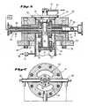
- Fig. 4 is a cross sectional view of the vacuum chamber and delivery assembly according to a preferred embodiment of the present invention.
- Fig. 4 is taken along section line 4-4 of Fig. 3.
- sample delivery assembly 60 includes plunger housing 64, plunger 62 extending from the plunger housing and terminating at sample holder 70.
- the plunger 62 is connected to plunger head 71 which is adapted to receive the sample holder.
- the sample holder includes a metal base 72 connected to foam backing 73 upon which the sample 74 is mounted. This sample holder design minimizes compressive distortion of the tissue specimen.
- an insulator such as Thermanox® is used as the sample backing to retard the transfer of conductive heat from the sample holder.
- Thermanox® is used as the sample backing to retard the transfer of conductive heat from the sample holder.
- the sample delivery assembly also includes pneumatic conduit 63.
- the sample delivery assembly is mounted on base plate 67 extending from the top of the circular sidewall 68 which is mounted on upper end plate 23 of the vacuum chamber 21.
- Vacuum chamber 21 comprises upper end plate 23, conduit housing 45 and vacuum chamber housing 47. These components are sealed together in sealing engagement with vacuum chamber screws 90.
- Shutter 65 seals the opening of upper end plate 23 and is connected to rod 66 extending from rod housing 75.
- the shutter assembly 61 comprises shutter 65, rod 66, rod housing 75 and pneumatic conduit 76.
- the rod housing 75 is mounted on circular sidewall 68, and is pneumatically actuated to move the shutter to open the vacuum chamber 21.
- a source of fluid coolant 40 supplies cryogenic cooling fluid to inlet conduit 22, through cooling jacket chamber 26 and out the outlet conduit 28.
- Cooling jacket 27 is mounted within the vacuum chamber 21.
- the cooling jacket 27 holds the lower region ("cryofinger") 25 of the cryogenic block.
- the cryofinger 25 extends into the cooling jacket chamber 26 which is supplied with fluid such as liquid nitrogen or helium during the cooling process.
- cooling jacket 27 includes a bellows member 19 (Fig. 10) which reduces fatigue caused by thermal contraction and expansion during the consecutive slamming of tissue specimens.
- Vacuum jacket 58 thermally isolates cryogenic effects of the liquid coolant from all but the cryogenic components of the apparatus, i.e., the cryogenic block.
- the cryo-slam surface 20 may be composed of copper, chromium, gold, silver, diamond or sapphire or combinations thereof or other suitable means having high heat conductivity at low temperatures and providing a mirror finished flat smooth surface for contact with tissue samples.
- Preferred cryo-slam surfaces include copper with a sapphire outer portion or copper with a diamond outer portion. Oxidation of a copper surface occurs rapidly when exposed to the atmosphere. It is desirable to reduce any oxidation of the cryo-slam surface which would result in reduced thermal conductivity. Therefore, the cryo-slam surface is preferably double gold-plated copper which reduces oxidation of its surface and eliminates the need for repeated polishing.
- cryo-slam surface 20 is copper plated with 5u inch acid gold and 45u inch alkaline gold.
- the preferred cryofinger 25 is 100% copper and is maintained within cooling jacket chamber 26.
- the cryo-slam surface 20 may be removed from the cryofinger 25 for cleaning or replacement with a cryo-slam surface having an alternate shape or composition.
- the vacuum chamber housing 47 comprises vacuum chamber housing flange 42, and vacuum chamber housing sidewall 24.
- a source of dry inert gas 50 is attached to supply a dry helium or nitrogen gas to the vacuum chamber 21.
- the inert gas source 50 is connected to vacuum reversal valve 51 and vacuum reversal conduit 54.
- the vacuum chamber housing flange 42 is mounted on mounting flange 55 and affixed by mounting flange screw 93 on the horizontal surface 12.
- Fig. 5 shows the vacuum chamber 21 and cooling jacket 27 in more detail.
- shutter 65 seals the top of upper end plate 23.
- the shutter 65 is opened when the rod 66 is pneumatically actuated to move the shutter 65 out of sealing relationship with the upper end plate 23.
- An o-ring 37 is included in the upper end plate 23 for sealing with the shutter 65.
- the cryo-slam surface 20 is shown in Fig. 5 connected to the cryofinger 25 maintained within the cooling jacket chamber 26.
- the cooling jacket 27 further includes cooling jacket upper end plate 29 and cooling jacket lower end plate 44. Cooling jacket 27 is sealed to the lower side of conduit housing 45, while cooling jacket upper end plate 29 is sealed to the top of the conduit housing 45.
- Upper cooling jacket screw 91 connects the cooling jacket 27 and conduit housing 45.
- Cooling jacket 27 further includes cooling jacket upper flange 52 and lower flange 53.
- the lower flange 53 is connected to cooling jacket lower end plate 44 with lower cooling jacket screw 92.
- Cooling jacket chamber 26 is sealed to hold a fluid coolant such as liquid nitrogen or helium which is circulated through the cooling jacket 27.
- a fluid coolant such as liquid nitrogen or helium which is circulated through the cooling jacket 27.
- a source of fluid coolant 40 supplies cryogenic fluid through cooling inlet conduit 22 which introduces the fluid into the cooling jacket chamber 26 and out the cooling outlet conduit 28. Conduits 22 and 28 are surrounded by vacuum conduit 58. Also shown in Fig. 5 is vacuum chamber housing 47 which is mounted on mounting flange 55 with vacuum chamber screws 90.
- a source of dry inert gas 50 supplies a noncondensable gas such as dry helium or nitrogen through vacuum reversal conduit 54, controlled by valve 51, which provide access through vacuum chamber housing sidewall 24. The type and temperature of the gas used for vacuum reversal are independently variable.
- conduit housing 45 includes cooling inlet conduit 22 and cooling outlet conduit 28.
- the inlet conduit and outlet conduit are surrounded by vacuum conduit 58.
- conduit housing orifice 57 which is a portion of the vacuum chamber 21.
- the vacuum chamber 21 extends both below and above the conduit housing ⁇ 45.
- Fig. 7 is an exploded perspective view of the vacuum chamber 21 according to a preferred embodiment of the present invention.
- shutter 65 is removably connected to rod 66, which seals off the aperture 36 in the vacuum chamber upper end plate 23.
- a seal or o-ring 37 is provided within concentric groove 35 in the vacuum chamber upper end plate 23.
- the upper end plate 23 comprises the top portion of vacuum chamber 21 (Fig. 5). Due to the extreme temperature and pressure conditions, the o-ring 37 may be manufactured of special materials to assure a seal.
- a conflat flange copper gasket 46 is used to seal the vacuum chamber upper end plate 23 against the conduit housing 45.
- the cryo-slam surface 20 is removably connected to cryofinger 25 which is maintained within cooling jacket 27 (Fig. 5).
- An electrical connector 82 for the heating unit extends from the cryofinger 25.
- An electrical connector 84 for an embedded thermocouple extends from the cryofinger. Electrical connectors 82 and 84 extend outside vacuum chamber housing 47 through grommet 80 (Fig. 14).
- the cryofinger 25 of the cryogenic block houses a heating unit which in the preferred embodiment is heating element or cartridge heater 81.
- the heating element of cartridge heater 81 is shown in Fig. 11.
- the heating element or cartridge heater 81 is connected to electrical connector 82, preferably having a temperature regulator. Heating element or cartridge heater 81 thus enables automatic regeneration of the cryo-slam surface 20 (Fig. 10) for rapid turnover of samples.
- the heating element or cartridge 81 may be used to regulate the temperature of the cryo-slam surface 20, depending upon the temperature desired for slamming the particular tissue specimen.
- Heating element or cartridge heater 81 is housed in the cryofinger 25 (Fig. 10) by conventional fastening means. In a preferred embodiment (Figs. 10-11), the cryofinger 25 extends below the cooling jacket 27 (bellows member 19) and into the vacuum chamber 21.
- the lower surface of cryofinger 25 contains orifice 69 which becomes an inner cavity fashioned to enclose the heating unit 81.
- the heating unit 81 may be secured within the inner cavity of cryofinger 25 by an interference fit or, as shown in Fig. 11, may be further secured by a back-up cylinder 78 and set-screws 79. This arrangement allows easy access to the heating unit for replacement purposes.
- the electrical connector 82 is thermally insulated from the cooling fluid in chamber 26 which increases the operational life of the heating unit 81.
- Heating element 81 is electrically connected to energy means, not shown, by electrical connector 82.
- a thermocouple is embedded within the upper portion of cryofinger 25 to monitor the temperature of the cryo-slam surface 20.
- the cooling jacket 27 is enclosed within the vacuum chamber 21.
- the cooling jacket 27 comprises cooling jacket upper end plate 29, annular cooling jacket seal 32, and a copper gasket 33 for sealing the upper end plate 29 with the upper surface of conduit housing 45.
- the cryofinger 25 is slideably mounted within the cooling jacket upper end plate 29 and bonded with the annular cooling jacket seal 32.
- the cooling jacket chamber 26 is sealed from the vacuum chamber 21 while the cryo-slam surface 20 extends from the top of the cooling jacket 27.
- conduit housing 45 having conduit housing orifice 57 (Fig. 7) extending therethrough, along with the fittings necessary to receive cooling inlet conduit 22 and cooling outlet conduit 28, which circulates a fluid coolant through the cooling jacket chamber 26.
- the conduit housing orifices 57 are part of the vacuum chamber 21.
- Conflat flange copper gasket 48 is provided to seal the conduit housing 45 with the vacuum chamber flange 42 of the vacuum chamber housing 47.
- the vacuum chamber housing 47 further includes vacuum chamber housing sidewall 24 and bottom surface of housing 49 (Fig. 7).
- the cooling jacket 27 seals the cooling jacket body upper flange 52 with the conduit housing 45.
- Copper gasket 41 seals the cooling jacket lower flange 53 to the cooling jacket lower end plate 44.
- the cooling jacket 27 is tightly sealed within the vacuum chamber 21.
- Upper cooling jacket screw 91 and lower cooling jacket screw 92 are provided to assemble the cooling jacket with the conduit housing 45.
- Vacuum chamber screws 90 further are provided to assemble the vacuum chamber upper end plate 23, conduit housing 45 and vacuum chamber housing 47.
- An external vacuum pump 59 (Fig. 8) is utilized to create a vacuum in vacuum chamber 21.
- the vacuum pump 59 is preferably a vibration isolated cryosorption pump or vane pump or equivalent device for creating a vacuum of at least 10 ⁇ 4 mbar in the chamber 21.
- the vacuum pump 59 can be any of a variety of commercially available pumping apparatus.
- the cooling jacket 27 is provided with inlet conduit 22 for conveying fluid coolant from a reservoir to vacuum chamber 21. Additionally, the cooling jacket 27 is provided with outlet conduit 28 for purging the cooling fluid.
- An external source of coolant with controls is used to regulate the supply of coolant to cooling jacket 27.
- the fluid coolant may be selected from liquid nitrogen, liquid helium and the like.
- One advantage of the apparatus and method of the invention is the ability to supply cooling fluids at substantially increased pressures than prior art devices. Cooling fluids are typically supplied at a pressure from about 10-25 psi, preferably of at a pressure of 15-20 psi and most preferably at 20 psi.
- Fig. 8 the operation of the present invention in the preferred embodiment is set forth below.
- the shutter 65 enclosing the vacuum chamber 21 is closed.
- the vacuum pump 59 is actuated to secure a high vacuum in the vacuum chamber 21.
- cooling fluid is introduced to the cooling jacket 27 through cooling inlet conduit 22 and out the cooling outlet 28 (Fig. 14).
- a source of fluid coolant 40 is used to cool the cryo-slam surface 20 (Fig. 14) to a temperature of preferably -175°C or below.
- the particular temperature for the cryo-slam surface 20 (Fig. 14) may be varied according to the present invention. The temperature desired depends on factors such as the composition of the cryo-slam surface and the tissue specimen.
- a thermocouple (not shown) is used to sense the temperature of the cryo-slam surface during the cooling process.
- the vacuum source 30 (Fig. 14) is isolated and a dry inert gas 50 is introduced to reverse the vacuum within the vacuum chamber 21.
- the gas must be noncondensable at the cryogenic block temperature.
- dry helium gas is used to reverse the vacuum.
- dry nitrogen gas at room temperature may be used.
- Vacuum reversal valve 51 and conduit 54 are used to allow dry helium gas or dry nitrogen gas at room temperature to enter the vacuum chamber 21 and raise the pressure inside the chamber to atmospheric pressure. The use of noncondensable dry helium gas or dry nitrogen gas at room temperature prevents precooling of the tissue specimen during movement towards cryo-slam surface 20.
- any other noncondensable inert gas may be used, preferably at room temperature, to raise the pressure inside the vacuum chamber 21 without undesirable condensation on the cryo-slam surface 20 or precooling of the tissue specimen.
- the vacuum chamber 21 reaches atmospheric pressure, wherein the pressure inside of the shutter 65 equals the outside of the shutter, the shutter 65 is pneumatically actuated to open the access to the vacuum chamber 21. Pneumatic actuation provides a constant rate of descent of the plunger 62 through the opening in the vacuum chamber upper end plate 23 and against the cryo-slam surface 20.
- the fluid coolant source 40 and vacuum pump 59 are turned off during the slamming of the tissue sample against the cryo-slam surface 20, so that the cooling fluid will not impart any undesired vibration to the cooling surface during the slamming process.
- the sample is maintained against the cryo-slam surface for about 10 seconds to effectively establish thermal inertia in the sample and sample holder prior to removal.
- cryo-slam surface preferably is a temperature of -265°C to -175°C, depending upon the particular fluid coolant means employed.
- the fluid coolant source 40 may be reactuated.
- the tissue specimen may remain in contact with the cryo-slam surface 20 for a desired period of time.
- the tissue specimen may be removed from the cryo-slam surface 20 and placed in a liquid nitrogen dewar for storage and maintained at a cool temperature after it is removed from the sample holder.
- the pneumatic shutter is then closed against the upper end plate 23.
- the heating unit 81 is then activated to raise the temperature of the cryo-slam surface 20.
- the shutter 65 be closed and a vacuum drawn during heating of the surface to reduce the amount of condensation and/or contaminants deposited on the cryo-slam surface 20.
- the heating step is accomplished under vacuum conditions to allow sublimation without contamination.
- the cryo-slam surface 20 reaches the desired temperature, preferably room temperature, the cryogenic surface 20 may be cleaned.
- the source of fluid coolant is shut off so that the desired temperature may be reached.
- the vacuum reversal valve 51 is actuated only to raise the pressure inside the vacuum chamber 21 to atmospheric pressure prior to slamming the sample against the cryo-slam surface 20.
- the vacuum reversal valve 51 is deactivated as soon as atmospheric pressure is reached.
- vacuum pump 59 is re-actuated to obtain a vacuum in the vacuum chamber 21 during regeneration of the cryo-slam surface.
- the turnaround time between each sequential tissue specimen has been slow, due to the time for heating the block and reactivating the entire cooling system.
- the turnaround regeneration time is reduced to between 3-5 minutes or less.
- cryo-slam i.e., vitrify
- the cryo-slam surface is heated to preferably room temperature, cleaned and rapidly recooled between each tissue specimen.
- the cryo-slam surface is in a high hydrocarbon free vacuum.
- the condensation on the cryo-slam surface and/or contamination of the cryo-slam surface does not occur prior to application of the tissue sample. Precooling of the sample and condensation on the cryo-slam surface is prevented by introducing room temperature dry helium gas, dry nitrogen inert gas, or other noncondensable gas at room temperature, into the vacuum chamber.
- the present invention also eliminates problems of vibration to the cryo-slam surface due to movement of cooling fluid or liquid helium and helium gas proximate to the surface before slamming.
- the pneumatic shutter and sample delivery assembly also eliminate problems of timing between opening of the shutter and slamming the tissue specimen against the cryo-slam surface.
- cryo-slamming apparatus of the present invention is associated with a microprocesser.
- the microprocesser may be adapted to control functions such as: vacuum chamber pressure, cryogenic block temperature, process timing of the plunger and shutter, and sample-cryogenic block dwell time.
Landscapes
- Chemical & Material Sciences (AREA)
- Engineering & Computer Science (AREA)
- Physics & Mathematics (AREA)
- Health & Medical Sciences (AREA)
- Analytical Chemistry (AREA)
- Mechanical Engineering (AREA)
- Thermal Sciences (AREA)
- General Engineering & Computer Science (AREA)
- Chemical Kinetics & Catalysis (AREA)
- Life Sciences & Earth Sciences (AREA)
- Combustion & Propulsion (AREA)
- Biochemistry (AREA)
- General Health & Medical Sciences (AREA)
- General Physics & Mathematics (AREA)
- Immunology (AREA)
- Pathology (AREA)
- Sampling And Sample Adjustment (AREA)
- Investigating Or Analysing Biological Materials (AREA)
Applications Claiming Priority (2)
| Application Number | Priority Date | Filing Date | Title |
|---|---|---|---|
| US07/284,989 US5044165A (en) | 1986-12-03 | 1988-12-15 | Cryo-slammer |
| US284989 | 1988-12-15 |
Publications (2)
| Publication Number | Publication Date |
|---|---|
| EP0373738A2 true EP0373738A2 (de) | 1990-06-20 |
| EP0373738A3 EP0373738A3 (de) | 1991-01-30 |
Family
ID=23092287
Family Applications (1)
| Application Number | Title | Priority Date | Filing Date |
|---|---|---|---|
| EP19890303113 Withdrawn EP0373738A3 (de) | 1988-12-15 | 1989-03-29 | Gerät für ultra-schnelle Kühlung auf kryogene Temperaturen |
Country Status (5)
| Country | Link |
|---|---|
| US (1) | US5044165A (de) |
| EP (1) | EP0373738A3 (de) |
| JP (1) | JP2608953B2 (de) |
| AU (1) | AU627718B2 (de) |
| CA (1) | CA1320646C (de) |
Cited By (3)
| Publication number | Priority date | Publication date | Assignee | Title |
|---|---|---|---|---|
| WO2009065585A2 (en) | 2007-11-20 | 2009-05-28 | MAX-PLANCK-Gesellschaft zur Förderung der Wissenschaften e.V. | Ultra-rapid freezing device and method |
| WO2014015962A1 (de) | 2012-07-25 | 2014-01-30 | Fraunhofer-Gesellschaft zur Förderung der angewandten Forschung e. V. | Verfahren und vorrichtung zur hochgeschwindigkeits-temperierung einer probe |
| WO2021198768A3 (en) * | 2020-03-31 | 2022-04-28 | Preci Health Sa | Body fluids sampling device and method of using the same |
Families Citing this family (84)
| Publication number | Priority date | Publication date | Assignee | Title |
|---|---|---|---|---|
| US5132089A (en) * | 1991-01-31 | 1992-07-21 | Lightfoot Fred G | Hand-held cryofixation apparatus |
| US5427950A (en) * | 1992-01-18 | 1995-06-27 | Kabushiki Kaisha Seitai Kagaku Kankyusho | Method for radioactivity measurement, process for preparing sample and device therefor |
| US6161543A (en) * | 1993-02-22 | 2000-12-19 | Epicor, Inc. | Methods of epicardial ablation for creating a lesion around the pulmonary veins |
| US6409722B1 (en) | 1998-07-07 | 2002-06-25 | Medtronic, Inc. | Apparatus and method for creating, maintaining, and controlling a virtual electrode used for the ablation of tissue |
| US5897553A (en) | 1995-11-02 | 1999-04-27 | Medtronic, Inc. | Ball point fluid-assisted electrocautery device |
| US5689961A (en) | 1996-01-30 | 1997-11-25 | Organogenesis Inc. | Ice seeding apparatus for cryopreservation systems |
| NL1003024C2 (nl) | 1996-05-03 | 1997-11-06 | Tjong Hauw Sie | Prikkelgeleidingsblokkeringsinstrument. |
| US6096037A (en) | 1997-07-29 | 2000-08-01 | Medtronic, Inc. | Tissue sealing electrosurgery device and methods of sealing tissue |
| US6537248B2 (en) | 1998-07-07 | 2003-03-25 | Medtronic, Inc. | Helical needle apparatus for creating a virtual electrode used for the ablation of tissue |
| US6706039B2 (en) | 1998-07-07 | 2004-03-16 | Medtronic, Inc. | Method and apparatus for creating a bi-polar virtual electrode used for the ablation of tissue |
| US6214054B1 (en) | 1998-09-21 | 2001-04-10 | Edwards Lifesciences Corporation | Method for fixation of biological tissues having mitigated propensity for post-implantation calcification and thrombosis and bioprosthetic devices prepared thereby |
| US6692450B1 (en) | 2000-01-19 | 2004-02-17 | Medtronic Xomed, Inc. | Focused ultrasound ablation devices having selectively actuatable ultrasound emitting elements and methods of using the same |
| US8241274B2 (en) | 2000-01-19 | 2012-08-14 | Medtronic, Inc. | Method for guiding a medical device |
| US8221402B2 (en) | 2000-01-19 | 2012-07-17 | Medtronic, Inc. | Method for guiding a medical device |
| US7706882B2 (en) | 2000-01-19 | 2010-04-27 | Medtronic, Inc. | Methods of using high intensity focused ultrasound to form an ablated tissue area |
| US6447443B1 (en) | 2001-01-13 | 2002-09-10 | Medtronic, Inc. | Method for organ positioning and stabilization |
| US8048070B2 (en) | 2000-03-06 | 2011-11-01 | Salient Surgical Technologies, Inc. | Fluid-assisted medical devices, systems and methods |
| US6652583B2 (en) * | 2000-04-07 | 2003-11-25 | Rhode Island Hospital | Cardiac valve replacement |
| US6488680B1 (en) | 2000-04-27 | 2002-12-03 | Medtronic, Inc. | Variable length electrodes for delivery of irrigated ablation |
| US6514250B1 (en) | 2000-04-27 | 2003-02-04 | Medtronic, Inc. | Suction stabilized epicardial ablation devices |
| EP1278471B1 (de) | 2000-04-27 | 2005-06-15 | Medtronic, Inc. | Vibrationsempfindliche ablationsvorrichtung |
| US6926669B1 (en) | 2000-10-10 | 2005-08-09 | Medtronic, Inc. | Heart wall ablation/mapping catheter and method |
| US6558629B1 (en) | 2000-11-13 | 2003-05-06 | Bradley Products, Inc. | Device and method for preparing tissue specimen for histologic sectioning |
| DE10065143B4 (de) * | 2000-12-23 | 2007-12-27 | Leica Mikrosysteme Gmbh | Probenhalter für eine Hochdruckgefriereinrichtung |
| US7740623B2 (en) | 2001-01-13 | 2010-06-22 | Medtronic, Inc. | Devices and methods for interstitial injection of biologic agents into tissue |
| US20040138621A1 (en) | 2003-01-14 | 2004-07-15 | Jahns Scott E. | Devices and methods for interstitial injection of biologic agents into tissue |
| US7628780B2 (en) | 2001-01-13 | 2009-12-08 | Medtronic, Inc. | Devices and methods for interstitial injection of biologic agents into tissue |
| US6648883B2 (en) | 2001-04-26 | 2003-11-18 | Medtronic, Inc. | Ablation system and method of use |
| US6699240B2 (en) | 2001-04-26 | 2004-03-02 | Medtronic, Inc. | Method and apparatus for tissue ablation |
| US6807968B2 (en) | 2001-04-26 | 2004-10-26 | Medtronic, Inc. | Method and system for treatment of atrial tachyarrhythmias |
| US7959626B2 (en) * | 2001-04-26 | 2011-06-14 | Medtronic, Inc. | Transmural ablation systems and methods |
| US6663627B2 (en) | 2001-04-26 | 2003-12-16 | Medtronic, Inc. | Ablation system and method of use |
| US7250048B2 (en) | 2001-04-26 | 2007-07-31 | Medtronic, Inc. | Ablation system and method of use |
| EP2275050A1 (de) | 2001-09-05 | 2011-01-19 | Salient Surgical Technologies, Inc. | Flüssigkeitsgestützte elektrochirurgische Vorrichtungen, Verfahren und Systeme |
| US6656175B2 (en) | 2001-12-11 | 2003-12-02 | Medtronic, Inc. | Method and system for treatment of atrial tachyarrhythmias |
| US6878168B2 (en) | 2002-01-03 | 2005-04-12 | Edwards Lifesciences Corporation | Treatment of bioprosthetic tissues to mitigate post implantation calcification |
| US6827715B2 (en) | 2002-01-25 | 2004-12-07 | Medtronic, Inc. | System and method of performing an electrosurgical procedure |
| US7967816B2 (en) | 2002-01-25 | 2011-06-28 | Medtronic, Inc. | Fluid-assisted electrosurgical instrument with shapeable electrode |
| US7294143B2 (en) | 2002-05-16 | 2007-11-13 | Medtronic, Inc. | Device and method for ablation of cardiac tissue |
| US7118566B2 (en) | 2002-05-16 | 2006-10-10 | Medtronic, Inc. | Device and method for needle-less interstitial injection of fluid for ablation of cardiac tissue |
| US7083620B2 (en) | 2002-10-30 | 2006-08-01 | Medtronic, Inc. | Electrosurgical hemostat |
| US7497857B2 (en) | 2003-04-29 | 2009-03-03 | Medtronic, Inc. | Endocardial dispersive electrode for use with a monopolar RF ablation pen |
| US8333764B2 (en) | 2004-05-12 | 2012-12-18 | Medtronic, Inc. | Device and method for determining tissue thickness and creating cardiac ablation lesions |
| ES2308505T3 (es) | 2004-05-14 | 2008-12-01 | Medtronic, Inc. | Sistema de utilizacion de energia ultrasonica enfocada de alta intens idad para formar una zona de tejido recortado. |
| EP1750608B1 (de) | 2004-06-02 | 2012-10-03 | Medtronic, Inc. | Ablationsvorrichtung mit backen |
| EP1750606B1 (de) | 2004-06-02 | 2010-05-05 | Medtronic, Inc. | Zusammengesetzte bipolare ablationsvorrichtung |
| WO2005120377A1 (en) | 2004-06-02 | 2005-12-22 | Medtronic, Inc. | Clamping ablation tool |
| WO2005120375A2 (en) | 2004-06-02 | 2005-12-22 | Medtronic, Inc. | Loop ablation apparatus and method |
| US8926635B2 (en) * | 2004-06-18 | 2015-01-06 | Medtronic, Inc. | Methods and devices for occlusion of an atrial appendage |
| US8409219B2 (en) | 2004-06-18 | 2013-04-02 | Medtronic, Inc. | Method and system for placement of electrical lead inside heart |
| US8663245B2 (en) | 2004-06-18 | 2014-03-04 | Medtronic, Inc. | Device for occlusion of a left atrial appendage |
| US7293426B2 (en) * | 2004-10-05 | 2007-11-13 | Washington University | Apparatus for freezing a biological sample |
| JP5478884B2 (ja) | 2005-09-26 | 2014-04-23 | ライフセル コーポレーション | 乾燥血小板組成物 |
| EP2008037A2 (de) * | 2006-03-30 | 2008-12-31 | Cornell Research Foundation, Inc. | System und verfahren für erhöhte kühlraten bei der schnellkühlung kleiner biologischer proben |
| US20080039746A1 (en) | 2006-05-25 | 2008-02-14 | Medtronic, Inc. | Methods of using high intensity focused ultrasound to form an ablated tissue area containing a plurality of lesions |
| US8007992B2 (en) | 2006-10-27 | 2011-08-30 | Edwards Lifesciences Corporation | Method of treating glutaraldehyde-fixed pericardial tissue with a non-aqueous mixture of glycerol and a C1-C3 alcohol |
| US9101691B2 (en) | 2007-06-11 | 2015-08-11 | Edwards Lifesciences Corporation | Methods for pre-stressing and capping bioprosthetic tissue |
| ES2840251T3 (es) | 2007-07-10 | 2021-07-06 | Lifecell Corp | Composiciones acelulares de matriz tisular para reparación de tejidos |
| JP5043199B2 (ja) * | 2007-11-09 | 2012-10-10 | プラクスエア・テクノロジー・インコーポレイテッド | 生物材料を制御された速度で冷凍する方法及びシステム |
| US8357387B2 (en) | 2007-12-21 | 2013-01-22 | Edwards Lifesciences Corporation | Capping bioprosthetic tissue to reduce calcification |
| US8882756B2 (en) | 2007-12-28 | 2014-11-11 | Medtronic Advanced Energy Llc | Fluid-assisted electrosurgical devices, methods and systems |
| US20090186405A1 (en) * | 2008-01-17 | 2009-07-23 | Milton Chin | Rapid Chilling Device for Vitrification |
| US8821488B2 (en) | 2008-05-13 | 2014-09-02 | Medtronic, Inc. | Tissue lesion evaluation |
| US8056256B2 (en) * | 2008-09-17 | 2011-11-15 | Slack Associates, Inc. | Method for reconditioning FCR APG-68 tactical radar units |
| US8701307B2 (en) | 2008-09-17 | 2014-04-22 | Howard C. Slack | Method for cleaning and reconditioning FCR APG-68 tactical radar units |
| WO2010096809A1 (en) | 2009-02-23 | 2010-08-26 | Salient Surgical Technologies, Inc. | Fluid-assisted electrosurgical device and methods of use thereof |
| AT508018B1 (de) * | 2009-07-29 | 2010-10-15 | Leica Mikrosysteme Gmbh | Kryopräparationskammer zum manipulieren einer probe für die elektronenmikroskopie |
| BR122014006876B1 (pt) | 2010-03-23 | 2020-09-29 | Edwards Lifesciences Corporation | Método para preparar material de membrana de tecido bioprotético |
| US20110295249A1 (en) * | 2010-05-28 | 2011-12-01 | Salient Surgical Technologies, Inc. | Fluid-Assisted Electrosurgical Devices, and Methods of Manufacture Thereof |
| CN102946916B (zh) | 2010-06-17 | 2015-03-18 | 爱德华兹生命科学公司 | 通过化学修饰抗原性碳水化合物稳定生物假体组织的方法 |
| US8906601B2 (en) | 2010-06-17 | 2014-12-09 | Edwardss Lifesciences Corporation | Methods for stabilizing a bioprosthetic tissue by chemical modification of antigenic carbohydrates |
| US9138289B2 (en) | 2010-06-28 | 2015-09-22 | Medtronic Advanced Energy Llc | Electrode sheath for electrosurgical device |
| US8906012B2 (en) | 2010-06-30 | 2014-12-09 | Medtronic Advanced Energy Llc | Electrosurgical devices with wire electrode |
| US9351829B2 (en) | 2010-11-17 | 2016-05-31 | Edwards Lifesciences Corporation | Double cross-linkage process to enhance post-implantation bioprosthetic tissue durability |
| US8870864B2 (en) | 2011-10-28 | 2014-10-28 | Medtronic Advanced Energy Llc | Single instrument electrosurgery apparatus and its method of use |
| US10238771B2 (en) | 2012-11-08 | 2019-03-26 | Edwards Lifesciences Corporation | Methods for treating bioprosthetic tissue using a nucleophile/electrophile in a catalytic system |
| GB2513151B (en) | 2013-04-17 | 2015-05-20 | Siemens Plc | Improved thermal contact between cryogenic refrigerators and cooled components |
| US9974599B2 (en) | 2014-08-15 | 2018-05-22 | Medtronic Ps Medical, Inc. | Multipurpose electrosurgical device |
| KR102289821B1 (ko) * | 2014-10-23 | 2021-08-13 | 삼성전자주식회사 | 수송 장치 및 이를 이용하는 수송 방법 |
| JP6823300B2 (ja) * | 2017-01-20 | 2021-02-03 | 日本電子株式会社 | 試料作製装置 |
| US10194975B1 (en) | 2017-07-11 | 2019-02-05 | Medtronic Advanced Energy, Llc | Illuminated and isolated electrosurgical apparatus |
| EP3502649B1 (de) * | 2017-12-22 | 2021-01-27 | safematic GmbH | Verfahren zur entwässerung und kritischer-punkt-trocknung |
| US10833384B2 (en) * | 2018-06-27 | 2020-11-10 | International Business Machines Corporation | Thermalization of microwave attenuators for quantum computing signal lines |
| US20230338964A1 (en) * | 2020-09-11 | 2023-10-26 | The Regents Of The University Of California | Cryogenic milling techniques for fabrication of nanostructured electrodes |
Family Cites Families (58)
| Publication number | Priority date | Publication date | Assignee | Title |
|---|---|---|---|---|
| US3125096A (en) * | 1964-03-17 | Compressor | ||
| US2672032A (en) * | 1951-10-19 | 1954-03-16 | Towse Robert Albert Edward | Carcass freezing device |
| US3067589A (en) * | 1960-11-08 | 1962-12-11 | Specialties Dev Corp | Cooling apparatus |
| US3679450A (en) * | 1970-03-16 | 1972-07-25 | Roy Nutt | Biopsy method |
| US3928566A (en) * | 1970-08-14 | 1975-12-23 | Du Pont | Lyophilized biological products |
| US3932943A (en) * | 1970-08-14 | 1976-01-20 | E. I. Du Pont De Nemours And Company | Method of preparation of lyophilized biological products |
| US3745290A (en) * | 1972-03-01 | 1973-07-10 | Gen Electric | Inductively heatable utensils or vessels for heating,serving and storing food |
| US3942519A (en) * | 1972-12-26 | 1976-03-09 | Ultrasonic Systems, Inc. | Method of ultrasonic cryogenic cataract removal |
| US3982541A (en) * | 1974-07-29 | 1976-09-28 | Esperance Jr Francis A L | Eye surgical instrument |
| BE837262R (fr) * | 1975-05-23 | 1976-06-30 | Procede et dispositif de congelation rapide | |
| GB1560481A (en) * | 1975-07-09 | 1980-02-06 | Johnson Matthey Co Ltd | Complexes of osmium tetroxide |
| FR2337878A1 (fr) * | 1976-01-09 | 1977-08-05 | Anvar | Procede et appareil pour realiser des cryo-fractures |
| AT343941B (de) * | 1976-02-06 | 1978-06-26 | Reichert Optische Werke Ag | Verfahren und vorrichtung zur herstellung von praparaten fur die mikroskopie, insbesondere elektronenmikroskopie aus nativen histologischen objekten sowie physikochemisch ahnlichen produkten durch kryofixation |
| US4055904A (en) * | 1976-04-02 | 1977-11-01 | Tousimis Research Corporation | Automatic critical point drying apparatus |
| US4056855A (en) * | 1976-04-07 | 1977-11-08 | Charles Kelman | Intraocular lens and method of implanting same |
| US4030314A (en) * | 1976-04-07 | 1977-06-21 | John Frederick Strehler | Method and apparatus for preserving biological materials |
| US4063068A (en) * | 1976-08-12 | 1977-12-13 | Minnesota Mining And Manufacturing Company | Food heating and cooking receptacle |
| US4120991A (en) * | 1976-12-10 | 1978-10-17 | Technicon Instruments Corporation | Process for mounting tissue sections with an U.V. light curable mounting medium |
| US4278623A (en) * | 1977-01-11 | 1981-07-14 | Union Carbide Corporation | Ultra-fine fibers and method for making same |
| US4205059A (en) * | 1977-03-09 | 1980-05-27 | Hagens Gunther Von | Animal and vegetal tissues permanently preserved by synthetic resin impregnation |
| US4122853A (en) * | 1977-03-14 | 1978-10-31 | Spectra-Med | Infrared laser photocautery device |
| US4201319A (en) * | 1977-04-04 | 1980-05-06 | Frigitronics Of Conn., Inc. | Dispensing system employing liquid cryogen |
| DE2739796A1 (de) * | 1977-09-03 | 1979-03-15 | Reichert Optische Werke Ag | Einrichtung zur gefriertrocknung und gegebenenfalls kunstharz-impraegnation kleiner biologischer objekte fuer die elektronenmikroskopische untersuchung |
| DE2908794C2 (de) * | 1978-03-09 | 1984-09-13 | Japan Atomic Energy Research Institute, Tokio/Tokyo | Verfahren zur Herstellung eines eine physiologisch aktive Substanz enthaltenden Polymerpräparates |
| US4337240A (en) * | 1978-04-20 | 1982-06-29 | New England Nuclear Corporation | Denatured albumin complexes for radioscintigraphic imaging and evaluation of reticuloendothelial systems |
| US4197658A (en) * | 1978-05-12 | 1980-04-15 | Fts Systems, Inc. | Tissue freeze dryer |
| DE2935097A1 (de) * | 1978-09-07 | 1980-03-20 | Kuraray Co | Aethylen/vinylalkohol-copolymermembran |
| US4232453A (en) * | 1978-09-25 | 1980-11-11 | C. Reichert Optische Werke, Ag | Device for freeze drying and synthetic resin impregnation when necessary of small biological objects for electron microscopic examination |
| US4331591A (en) * | 1978-10-05 | 1982-05-25 | Ciba-Geigy Corporation | Chemical process for the production of α-aminophosphonic acids and peptide derivatives |
| US4266111A (en) * | 1979-01-11 | 1981-05-05 | Wentgate Engineers (1976) Limited | Apparatus for transferring work through a region of reduced pressure for the performance of an operation thereon |
| DE2914181C2 (de) * | 1979-04-07 | 1982-06-16 | Kernforschungsanlage Jülich GmbH, 5170 Jülich | Verfahren und Vorrichtung zum Trocknen temperaturempfindlicher Güter der Pharma- und Nahrungsmittelindustrie |
| DE2944806A1 (de) * | 1979-11-06 | 1981-05-14 | C. Reichert Optische Werke Ag, Wien | Einrichtung zur metallspiegel-kryofixation sowie zur nachfolgenden kryopraeparation biologischer objekte |
| US4336691A (en) * | 1979-12-13 | 1982-06-29 | The Board Of Trustees Of The Leland Stanford Junior University | Cryojet rapid freezing apparatus |
| US4379003A (en) * | 1980-07-30 | 1983-04-05 | Bell Telephone Laboratories, Incorporated | Magnetic devices by selective reduction of oxides |
| DE3042578A1 (de) * | 1980-11-12 | 1982-06-24 | C. Reichert Optische Werke Ag, Wien | Inkubationseinrichtung zur fixation, entwaesserung und einbettung biologischer objekte fuer mikroskopische, insbesondere elektronenmikroskopische untersuchungen |
| FR2508993A1 (fr) * | 1981-07-01 | 1983-01-07 | Usifroid | Installation de lyophilisation a double serie d'etageres |
| DE3332586C2 (de) * | 1983-09-09 | 1986-03-20 | C. Reichert Optische Werke Ag, Wien | Vorrichtung zum Vermeiden des Verspritzens flüssiger Kühlmedien beim schnellen Einbringen biologisch-medizinischer Objekte in ein Kühlbad im Rahmen einer Immersions-Kryofixation |
| DE3234457C2 (de) * | 1982-09-17 | 1984-09-20 | C. Reichert Optische Werke Ag, Wien | Kühlbad zum raschen Abkühlen von Proben, insbesondere zur Kryofixation biologischer Objekte für eine nachfolgende licht- oder elektronenoptische Untersuchung |
| US4428821A (en) * | 1982-11-04 | 1984-01-31 | Exxon Research & Engineering Company | Oil shale extraction process |
| US4559298A (en) * | 1982-11-23 | 1985-12-17 | American National Red Cross | Cryopreservation of biological materials in a non-frozen or vitreous state |
| US4423600A (en) * | 1982-12-10 | 1984-01-03 | Mckenna Joan J | Method for preservation of living organic tissue by freezing |
| US4676070A (en) * | 1984-11-30 | 1987-06-30 | The Board Of Regents, The University Of Texas | Apparatus and method for cryopreparing biological tissue |
| US4567847A (en) * | 1983-08-23 | 1986-02-04 | Board Of Regents, The University Of Texas System | Apparatus and method for cryopreparing biological tissue for ultrastructural analysis |
| US4799361A (en) * | 1983-08-23 | 1989-01-24 | Board Of Regents, The University Of Texas System | Method for cryopreparing biological tissue for ultrastructural analysis |
| US4510169A (en) * | 1983-08-23 | 1985-04-09 | The Board Of Regents, The University Of Texas | Method and apparatus for cryopreparing biological tissue for ultrastructural analysis |
| US4742690A (en) * | 1983-08-23 | 1988-05-10 | Board Of Regents, The University Of Texas System | Apparatus and method for cryopreparing biological tissue for ultrastructural analysis |
| US4569850A (en) * | 1983-11-23 | 1986-02-11 | Auburn Research Foundation | Method for thermally blasting outer coverings from food products |
| DE3416790C2 (de) * | 1984-05-07 | 1986-09-04 | C. Reichert Optische Werke Ag, Wien | Vorrichtung zur Kryofixation nativer Objekte mittels eines flüssigen Kühlmediums oder eines Metallspiegels |
| DE3416789C2 (de) * | 1984-05-07 | 1986-09-04 | C. Reichert Optische Werke Ag, Wien | Vorrichtung zur alternativen Kryofixation biologisch-medizinischer oder technischer Objekte mit hohem Wasser-bzw. Flüssigkeitsgehalt durch Immersion bzw. am Metallspiegel |
| US4563883A (en) * | 1984-09-17 | 1986-01-14 | C. Reichert Optische Werke Ag | Specimen immersing device |
| US4619257A (en) * | 1984-11-30 | 1986-10-28 | Board Of Regents, The University Of Texas System | Apparatus and method for cryopreparing corneal tissue for surgical procedures |
| US4580411A (en) * | 1985-04-01 | 1986-04-08 | Orfitelli James S | Liquid nitrogen freezer |
| US4688387A (en) * | 1985-11-12 | 1987-08-25 | Vital Force, Inc. | Method for preservation and storage of viable biological materials at cryogenic temperatures |
| DE3610748A1 (de) * | 1986-03-29 | 1987-10-01 | Reichert Optische Werke Ag | Einrichtung zur kryofixation ruhender objekte durch eine tiefgekuehlte hochglanzpolierte festkoerperflaeche, insbesondere einen metallspiegel |
| EP0250613B1 (de) * | 1986-06-23 | 1991-07-17 | Leybold Aktiengesellschaft | Kryopumpe und Verfahren zum Betrieb dieser Kryopumpe |
| US4807442A (en) * | 1986-12-03 | 1989-02-28 | Board Of Regents The University Of Texas System | Cryo-slamming apparatus and method for ultrarapid cooling of biological samples |
| US4707998A (en) * | 1986-12-03 | 1987-11-24 | The Board Of Regents, The University Of Texas | Apparatus and method for ultrarapid cooling of biological samples |
| US4751828A (en) * | 1987-08-21 | 1988-06-21 | Regents Of The University Of Minnesota | Freezing apparatus for biological tissue |
-
1988
- 1988-12-15 US US07/284,989 patent/US5044165A/en not_active Expired - Lifetime
-
1989
- 1989-03-20 AU AU31516/89A patent/AU627718B2/en not_active Expired
- 1989-03-29 EP EP19890303113 patent/EP0373738A3/de not_active Withdrawn
- 1989-04-06 CA CA000595966A patent/CA1320646C/en not_active Expired - Lifetime
- 1989-04-18 JP JP1098624A patent/JP2608953B2/ja not_active Expired - Lifetime
Cited By (5)
| Publication number | Priority date | Publication date | Assignee | Title |
|---|---|---|---|---|
| WO2009065585A2 (en) | 2007-11-20 | 2009-05-28 | MAX-PLANCK-Gesellschaft zur Förderung der Wissenschaften e.V. | Ultra-rapid freezing device and method |
| WO2009065585A3 (en) * | 2007-11-20 | 2010-03-11 | MAX-PLANCK-Gesellschaft zur Förderung der Wissenschaften e.V. | Ultra-rapid freezing device and method |
| WO2014015962A1 (de) | 2012-07-25 | 2014-01-30 | Fraunhofer-Gesellschaft zur Förderung der angewandten Forschung e. V. | Verfahren und vorrichtung zur hochgeschwindigkeits-temperierung einer probe |
| DE102012014791A1 (de) * | 2012-07-25 | 2014-01-30 | Fraunhofer-Gesellschaft zur Förderung der angewandten Forschung e.V. | Verfahren und Vorrichtung zur Hochgeschwindigkeits-Temperierung einer Probe |
| WO2021198768A3 (en) * | 2020-03-31 | 2022-04-28 | Preci Health Sa | Body fluids sampling device and method of using the same |
Also Published As
| Publication number | Publication date |
|---|---|
| EP0373738A3 (de) | 1991-01-30 |
| AU3151689A (en) | 1990-06-21 |
| JPH02171571A (ja) | 1990-07-03 |
| JP2608953B2 (ja) | 1997-05-14 |
| CA1320646C (en) | 1993-07-27 |
| US5044165A (en) | 1991-09-03 |
| AU627718B2 (en) | 1992-09-03 |
Similar Documents
| Publication | Publication Date | Title |
|---|---|---|
| US5044165A (en) | Cryo-slammer | |
| US4807442A (en) | Cryo-slamming apparatus and method for ultrarapid cooling of biological samples | |
| EP0364633A1 (de) | Verfahren und Vorrichtung zur schnellen Kühlung biologischer Proben durch Kontakt mit einer Oberfläche | |
| US4745771A (en) | Apparatus and method for cryopreparing biological tissue for ultrastructural analysis | |
| US5024830A (en) | Method for cryopreparing biological tissue for ultrastructural analysis | |
| US4567847A (en) | Apparatus and method for cryopreparing biological tissue for ultrastructural analysis | |
| US4676070A (en) | Apparatus and method for cryopreparing biological tissue | |
| US4865871A (en) | Method for cryopreparing biological tissue | |
| US4799361A (en) | Method for cryopreparing biological tissue for ultrastructural analysis | |
| EP0136014B1 (de) | Verfahren und Vorrichtung zur Vorbereitung bei niedrigen Temperaturen von biologischen Geweben für die Strukturanalyse | |
| US4619257A (en) | Apparatus and method for cryopreparing corneal tissue for surgical procedures | |
| Sargent | Low temperature scanning electron microscopy: advantages and applications | |
| Hodson et al. | Ultracryotomy: a technique for cutting ultrathin sections of unfixed frozen biological tissues for electron microscopy | |
| US4742690A (en) | Apparatus and method for cryopreparing biological tissue for ultrastructural analysis | |
| Sleytr et al. | Freeze‐fracturing: a review of methods and results | |
| Burstein et al. | Cryofixation of tissue surfaces by a propane jet for electron microscopy | |
| CA1311620C (en) | Cryo-slamming apparatus and method for ultrarapid cooling of biological samples | |
| Inoue et al. | A new freeze-drying instrument using t-butyl alcohol for scanning electron microscopy | |
| US20060070392A1 (en) | Apparatus for freezing a biological sample | |
| Terracio et al. | Ultrastructural observations on tissues processed by a quick-freezing, rapid-drying method: Comparison with conventional specimen preparation | |
| JPH02124085A (ja) | 生物学的組織を超高速で冷却する装置 | |
| Campbell et al. | A simple ethanol‐based freeze‐substitution technique for marine invertebrate embryos which allows retention of antigenicity | |
| CA1239289A (en) | Method and apparatus for cryopreparing biological tissue for ultrastructural analysis | |
| Chapman et al. | Freeze-fracture (-etch) electron microscopy | |
| Schiller et al. | Combined freeze-fracturing and autoradiography techniques: Freeze-fracture autoradiography |
Legal Events
| Date | Code | Title | Description |
|---|---|---|---|
| PUAI | Public reference made under article 153(3) epc to a published international application that has entered the european phase |
Free format text: ORIGINAL CODE: 0009012 |
|
| AK | Designated contracting states |
Kind code of ref document: A2 Designated state(s): AT BE CH DE ES FR GB GR IT LI LU NL SE |
|
| PUAL | Search report despatched |
Free format text: ORIGINAL CODE: 0009013 |
|
| AK | Designated contracting states |
Kind code of ref document: A3 Designated state(s): AT BE CH DE ES FR GB GR IT LI LU NL SE |
|
| 17P | Request for examination filed |
Effective date: 19910726 |
|
| 17Q | First examination report despatched |
Effective date: 19920626 |
|
| STAA | Information on the status of an ep patent application or granted ep patent |
Free format text: STATUS: THE APPLICATION IS DEEMED TO BE WITHDRAWN |
|
| 18D | Application deemed to be withdrawn |
Effective date: 19931012 |