EP0373742A2 - Tunneleinheit und Rasterkopf für ein Tunnelrastermikroskop - Google Patents
Tunneleinheit und Rasterkopf für ein Tunnelrastermikroskop Download PDFInfo
- Publication number
- EP0373742A2 EP0373742A2 EP89306245A EP89306245A EP0373742A2 EP 0373742 A2 EP0373742 A2 EP 0373742A2 EP 89306245 A EP89306245 A EP 89306245A EP 89306245 A EP89306245 A EP 89306245A EP 0373742 A2 EP0373742 A2 EP 0373742A2
- Authority
- EP
- European Patent Office
- Prior art keywords
- specimen
- scanning head
- stage
- unit according
- tunnel unit
- Prior art date
- Legal status (The legal status is an assumption and is not a legal conclusion. Google has not performed a legal analysis and makes no representation as to the accuracy of the status listed.)
- Granted
Links
Images









Classifications
-
- G—PHYSICS
- G01—MEASURING; TESTING
- G01Q—SCANNING-PROBE TECHNIQUES OR APPARATUS; APPLICATIONS OF SCANNING-PROBE TECHNIQUES, e.g. SCANNING PROBE MICROSCOPY [SPM]
- G01Q10/00—Scanning or positioning arrangements, i.e. arrangements for actively controlling the movement or position of the probe
- G01Q10/04—Fine scanning or positioning
-
- B—PERFORMING OPERATIONS; TRANSPORTING
- B82—NANOTECHNOLOGY
- B82Y—SPECIFIC USES OR APPLICATIONS OF NANOSTRUCTURES; MEASUREMENT OR ANALYSIS OF NANOSTRUCTURES; MANUFACTURE OR TREATMENT OF NANOSTRUCTURES
- B82Y35/00—Methods or apparatus for measurement or analysis of nanostructures
-
- G—PHYSICS
- G01—MEASURING; TESTING
- G01Q—SCANNING-PROBE TECHNIQUES OR APPARATUS; APPLICATIONS OF SCANNING-PROBE TECHNIQUES, e.g. SCANNING PROBE MICROSCOPY [SPM]
- G01Q30/00—Auxiliary means serving to assist or improve the scanning probe techniques or apparatus, e.g. display or data processing devices
- G01Q30/08—Means for establishing or regulating a desired environmental condition within a sample chamber
-
- G—PHYSICS
- G01—MEASURING; TESTING
- G01Q—SCANNING-PROBE TECHNIQUES OR APPARATUS; APPLICATIONS OF SCANNING-PROBE TECHNIQUES, e.g. SCANNING PROBE MICROSCOPY [SPM]
- G01Q60/00—Particular types of SPM [Scanning Probe Microscopy] or microscopes; Essential components thereof
- G01Q60/10—STM [Scanning Tunnelling Microscopy] or apparatus therefor, e.g. STM probes
- G01Q60/16—Probes, their manufacture, or their related instrumentation, e.g. holders
-
- Y—GENERAL TAGGING OF NEW TECHNOLOGICAL DEVELOPMENTS; GENERAL TAGGING OF CROSS-SECTIONAL TECHNOLOGIES SPANNING OVER SEVERAL SECTIONS OF THE IPC; TECHNICAL SUBJECTS COVERED BY FORMER USPC CROSS-REFERENCE ART COLLECTIONS [XRACs] AND DIGESTS
- Y10—TECHNICAL SUBJECTS COVERED BY FORMER USPC
- Y10S—TECHNICAL SUBJECTS COVERED BY FORMER USPC CROSS-REFERENCE ART COLLECTIONS [XRACs] AND DIGESTS
- Y10S977/00—Nanotechnology
- Y10S977/84—Manufacture, treatment, or detection of nanostructure
- Y10S977/849—Manufacture, treatment, or detection of nanostructure with scanning probe
- Y10S977/86—Scanning probe structure
Definitions
- the present invention relates to a tunnel unit for a scanning tunneling microscope (hereinafter referred to as an "STM") and, more particularly, to a tunnel unit for a microscope of this type that has a coarse adjustment mechanism in which the scanning head is supported by the use of screws at three points.
- STM scanning tunneling microscope
- the present invention also relates to a scanning head used in a tunnel unit for an STM.
- Tunnel units for STMs that have a coarse adjustment mechanism, in which a scanning head having a probe mounted on a piezoelectric element is supported at three points by three screws provided through a specimen stage, are disclosed in, for instance, (1) J. Schneir, R. Sonnenfeld, 0. Marti, P. K. Hansma, J. E. Demuth and R. J. Hamers, "J. Appl. Phys.”, Vol. 63, No. 3, pp 717 to 721, 1988, and (2) 0. Marti, B. Drake, S. Gould and P. K. Hansma, "J. Vac. Sci. Technol. A.”, Vol. 6, No. 2, pp 287 to 290, 1988. Tunnel units according to these disclosures are shown in Figs.
- each tunnel unit has a scanning head 110 and a specimen stage 120.
- the scanning head 110 is provided with a piezoelectric element 113 capable of serving as a fine adjustment mechanism, and a probe 115 mounted on the piezoelectric element 113.
- the specimen stage 120 is provided with three screws 112 whose ends project from the surface of the stage 120 on which specimens, such as a specimen 124, may be placed.
- the scanning head 110 is disposed upon the ends of the three screws 112. When the screws 112 are advanced or retracted by suitably rotating them, the space between the probe 115 provided on the scanning head 110 and the specimen 124 placed on the specimen stage 120 is adjusted.
- An opening 10a for observing the probe 115 is formed through a side portion of the scanning head 110.
- the adjustment of the space between the probe 115 and the specimen 124 is performed while the tip portion of the probe 115 is observed through the opening 10a and at a magnified scale achieved by using a magnifier.
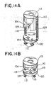
- the tunnel unit has, e.g., the following arrangement. That is, springs 129 are provided between the scanning head 110 and the specimen stage 120 to apply tensile force between these members, as shown in Fig. 14A, or spherical permanent magnets 119 are mounted on the ends of the screws 112 and, simultaneously, the scanning head 110 is formed of a magnetic body, as shown in Fig. 14B, thereby causing attraction by virtue of the magnetic force.
- the springs 129 which must be disassembled and reassembled each time the probe 115, the specimen 124 or the like is replaced, lead to inconvenience.
- the disassembly and reassembly of the springs 129 may cause the scanning head 110 to become inclined or subjected to impact, often resulting in the probe 115 coming into contact with the specimen stage 120, the specimen 124, or other associated parts, thereby damaging the probe 115, the specimen 124, or the like.
- a tunnel unit in which the spherical permanent magnets 119 are used involves the risk that, when the scanning head 110 is being disposed on the specimen stage 120, these members may be abruptly attracted to each other by the magnetic force such as to damage the probe 115, the specimen 124, or the like.
- permanent magnet materials having a large coercive force such as Alnico and ferrite, are in general hard and brittle, they can only be machined with difficulty. It is therefore difficult to machine such a material to assume a spherical configuration and, hence, to provide it with a low level of surface roughness at least at the part where it is to come into contact with the scanning head 110.
- Another problem is that, if a sintered magnet material is used, voids or cavities tend to be formed in the spherical surface after surface machining, while if permanent magnets in which a plastic material is charged with needle-shaped particles of an iron-cobalt alloy are used, they may encounter such problems as surface wear, a low level of rigidity, and a large coefficient of thermal expansion.
- the formation of the opening 10a in the scanning head 110 involves the following problem. If any sound waves should propagate from the outside of the tunnel unit into the scanning head 110 through the opening 10a, they may directly propagate to the piezoelectric element 113. In such cases, there is a risk of electric noise being generated.
- An STM of the type being discussed employs tunnel current which is about 1 nA and is thus very small relative to the bias voltage applied between the probe 115 and the specimen 124, which is about 20 mV. Therefore, if any electromagnetic waves should propagate from the outside into the scanning head 110 through the opening 10a, there is a risk of a great deal of electric noise being generated.
- Possible causes of electromagnetic waves entering the scanning head 110 include high voltage applied to the deflection electrode of a CRT combined with the STM to display, using the tunnel current, images of the surface of the specimen 124 for observation thereof.
- observation has hitherto been conducted, with the scanning head 110 covered with a case formed of a plastic or metal material.
- the efficiency of an observation operation deteriorates greatly.
- the present invention has been accomplished in order to overcome the above-described problems, and an object of the present invention is to provide a tunnel unit for a scanning tunneling microscope which possesses a high level of mechanical rigidity and which allows the probe, the specimen and other associated parts to be replaced safely and easily.
- Another object of the present invention is to provide a scanning head for a scanning tunneling microscope which is capable of reducing the possibility of electric noise being generated, and of ensuring an operation of excellent efficiency.
- a tunnel unit for a scanning tunneling microscope comprises: a specimen stage having a plurality of pole pieces joined together via a joint member formed of a non-magnetic material, and a specimen placing surface where the plurality of pole pieces and the joint member are exposed; a permanent magnet rotatably inserted within the specimen stage and at the portion at which the plurality of pole pieces are joined; a scanning head main body disposed above the specimen placing surface of the specimen stage in such a manner as to extend across the exposed joint member; a piezoelectric element fixed to the scanning head main body; a probe mounted on the piezoelectric element; and screw means formed of a magnetic material and turnably mounted on the scanning head main body, the screw means having its end portions in contact with the specimen placing surface of the specimen stage such as to support the scanning head main body above the specimen placing surface of the specimen stage.
- the tunnel unit for a scanning tunneling microscope may further comprise: an auxiliary stage having a plurality of auxiliary-stage pole pieces joined together via an auxiliary-stage joint member formed of a non-magnetic material, and a specimen stage disposing surface where the plurality of auxiliary-stage pole pieces and the auxiliary-stage joint member are exposed; and an auxiliary-stage permanent magnet rotatably inserted within the auxiliary stage and at the portion at which the plurality of auxiliary-stage pole pieces are joined, the specimen stage being disposed upon the specimen stage disposing surface of the auxiliary stage.
- a scanning head for a scanning tunneling microscope comprises: a scanning head main body having an opening formed therein for observation; a piezoelectric element fixed to the scanning head main body and disposed inside the scanning head main body; a probe mounted on the piezoelectric element and disposed in the vicinity of the opening of the scanning head main body; and an observation window body provided in the opening of the scanning head main body in such a manner as to close the opening, the observation window body being optically transparent and capable of preventing the inside of the scanning main body from being subjected to external disturbance.
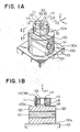
- a tunnel unit in accordance with a first embodiment of the present invention has a specimen stage 120 disposed upon a unit base 130, and a scanning head 110 disposed upon the specimen stage 120.
- the unit base 130 is formed of a material having strong magnetic properties, and has a specimen stage disposing surface 130a which is horizontal.
- the specimen stage 120 is formed of a material having a high magnetic permeability, and has two pole pieces 122 each having the configuration that can be obtained by longitudinally bisecting a circular cylinder. These pole pieces 122 are joined to each other via joint members 123 formed of a non-magnetic material to form one circular cylinder. The lower end face of this circular cylinder is disposed on the specimen stage disposing surface 130a of the unit base 130, while the upper end face defines a specimen placing surface 120a.
- a circular hole is formed at the joint of the two pole pieces 122, and the circular hole extends horizontally along the plane of joint.
- a permanent magnet 121 is rotatably received within the circular hole.
- the permanent magnet 121 has a configuration obtained by cutting portions of a round bar on two opposite sides by equal amounts, thereby providing flat cut-surfaces.
- the permanent magnet 121 is magnetized in the direction of the line connecting two circular arcs described by the remaining portions that are not cut.
- the flat cut-surfaces are provided in order to reduce the level of leakage of magnetic flux.
- the scanning head 110 is formed of a material having a high magnetic permeability, and it has a circular cylindrical scanning head main body 111 in which a through hole extending from the upper surface to the lower surface is formed in the vicinity of the center.
- a circular cylindrical piezoelectric element 113 is received within the through hole formed in the scanning head main body 111.
- the upper end portion of the piezoelectric element 113 is fixed to the inner wall of the through hole of the scanning head main body 111 by a fixing member 114 having electrically insulating properties.
- a probe 115 is mounted on a lower end portion of the piezoelectric element 113.
- three screws 112 are provided in the scanning head main body 111 at predetermined intervals around the circumference of the main body 111, and these screws 112 are threaded into the scanning head main body 111 by passing therethrough from the upper surface to the lower surface.
- the screws 112 are formed of a material having a high magnetic permeability.
- these three screws 112 are disposed in a plane (X-Y plane) at positions which define a regular or isosceles triangle.
- both the center of the piezoelectric element 113 and that of the probe 115 are positioned on a straight line D1 - D2 passing through the screw M2 and perpendicular to the base P of the isosceles triangle.
- the probe 115 is disposed at a position which is deviated from the base P of the isosceles triangle by a short distance B.
- each screw 112 that projects downward from the lower surface of the scanning head main body 111 is in contact with the specimen placing surface 120a of the specimen stage 120, thereby allowing the scanning head main body 111 to be located above the specimen placing surface 120a of the specimen stage 120, together with the piezoelectric element 113 and the probe 115.
- the length by which each screw 112 projects from the lower surface of the scanning head main body 111 can be adjusted by rotating the screw 112.
- the piezoelectric element 113 is provided with a plurality of electrodes for enabling the probe 115 to perform three-dimensional fine scanning.
- the tunnel unit is connected to various circuits such as a power source for applying voltage to these electrodes, a bias voltage source for applying voltage between the probe 115 and the specimen concerned, a feedback circuit operative to detect the tunnel current flowing between the probe 115 and the specimen and to maintain the tunnel current at a set value, and a display capable of displaying images of the surface of the specimen for observation.
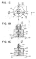
- the permanent magnet 121 is set at a rotational position thereof at which the line connecting the N and S poles of the permanent magnet 121 is parallel with the plane of joint of the two pole pieces 122.
- a specimen 124 is mounted on the specimen placing surface 120a of the specimen stage 120 and on one of the joint members 123 which is exposed on this specimen placing surface 120a. Thereafter, the specimen stage 120 with the specimen 124 is disposed upon the specimen stage disposing surface 130a of the unit base 130.
- the scanning head 110 is disposed upon the specimen placing surface 120a of the specimen stage 120 in such a manner that the tip of the probe 115 is positioned immediately above the specimen 124.
- the two M1 of the three screws 112 provided in the scanning head 110 are positioned on either side of the joint member 123 exposed on the specimen placing surface 120a of the specimen stage 120, while the other screw M2 is positioned on the exposed joint member 123.
- the height of the three screws 112 must be previously adjusted in order to prevent the tip of the probe 115 from either coming into contact with or becoming excessively far from the specimen 124 when the scanning head 110 is disposed upon the specimen placing surface 120a. Also at this time, as shown in Figs.
- the magnetic flux ⁇ flowing from the permanent magnet 121 flows substantially solely within the pole pieces 122. Consequently, no magnetic attraction occurs between the specimen stage 120 on one hand, and the unit base 130 or the scanning head 110 on the other. Thus, there is no risk of any magnetic attraction occurring abruptly when the specimen stage 120 is being disposed upon the unit base 130 or when the scanning head 110 is being disposed upon the specimen stage 120, thereby preventing the probe 115, the specimen 124 or the like from becoming damaged.
- the above-described state in which the magnetic flux ⁇ flowing from the permanent magnet 121 flows substantially solely within the pole pieces 122 will hereafter be referred to as the "open state of the magnetic circuit".
- the permanent magnet 121 is rotated in such a manner that the line connecting the N and S poles becomes normal to the plane of joint of the two pole pieces 122.
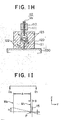
- three kinds of magnetic flux flow from the permanent magnet 121, as shown in Figs. 1G and 1H. That is, magnetic flux ⁇ 1 flows through the two screws M1, the scanning head main body 111, and the pole pieces 122, magnetic flux ⁇ 2 flows through the other screw M2 and the pole pieces 122, and magnetic flux ⁇ 3 flows through the unit base 130 and the pole pieces 122. Consequently, strong magnetic attraction occurs between the specimen stage 120 and the unit base 130 and between the specimen stage 120 and the scanning head 110, thereby achieving a highly rigid tunnel unit.
- the above-described state in which the magnetic flux ⁇ flows in this way from the permanent magnet 121 to the screws 112 of the scanning head 110 and to the unit base 130 will hereafter be referred to as the "closed state of the magnetic circuit".
- the screw M2 is rotated in such a manner as to bring the tip of the probe 115 close to the surface of the specimen 124.
- the probe 115 is separated the distance B from the base P of the isosceles triangle formed by the three screws 112. Therefore, if the distance from the base P to the screw M2 is called A (>B), as will be understood referring to Fig. 1I showing positional relationship in a vertical plane (Y-Z plane), when the screw M2 is rotated to provide a vertical difference H, the base P connecting the two screws M1 acts as the fulcrum of the vertical movement of the probe 115 through a vertical difference h which is reduced at a ratio substantially equal to the ratio B/A.
- This reduction ratio is determined by the distance C, shown in Fig. 1C, between the center O1 of the scanning head 111 and the center O2 of the circular cylindrical piezoelectric element 113 on which the probe 115 is mounted.
- the reduction ratio can be set at any desired value during manufacture of the tunnel unit.
- a certain bias voltage is applied between the probe 115 and the specimen 124 to which the probe 115 has been brought close in this way.
- the probe 115 is caused to perform two-dimensional (X-Y) scanning by the action of the piezoelectric element 113
- the screw M2 is rotated to bring the probe 115 closer to the specimen 124.
- the feedback circuit is actuated and feedback control with respect to the electrode that is provided in the piezoelectric element 113 in the Z direction is effected in such a manner as to maintain the tunnel current at the set value while the probe 115 performs scanning in the Z direction.
- the thus obtained X-Y scanning amount and the Z-direction feedback amount are displayed on the display, so that images of the surface of the specimen 124 are displayed for observation.
- FIG. 2A there is shown a tunnel unit in accordance with a second embodiment of the present invention.
- an internally threaded collar 1121 formed of a non-magnetic material is provided in a scanning head main body 111, and the collar 1121 is in threaded engagement with the one M2 of three screws 112 that is positioned on an exposed joint member 123.
- a metal sphere 1122 is provided at the end 112b of each of the screws 112 which are in contact with a specimen placing surface 120a.
- a plurality of electrodes 1131 are provided on the inner and outer peripheral surfaces of a circular cylindrical piezoelectric element 113, and the electrodes 1131 are connected to a plurality of leads 1132.
- a probe 115 is connected to a lead 1151.
- a permanent magnet 121 has a handle 1211 provided on one end thereof for causing the rotation of the permanent magnet 121.
- the permanent magnet 121 is received within a circular hole formed in pole pieces 122, with a lubricant 1212 being provided between the magnet 121 and the circular hole.
- tunnel unit of the second embodiment will be described in detail concerning the materials, the dimensions, etc. of members thereof.
- a material which has a small coefficient of thermal expansion, strong magnetic properties, and a high magnetic permeability may be used to form the scanning head main body 111.
- Invar Fe: 64 %, Ni: 36 %) which exhibits a thermal expansion coefficient of 2 x 10 ⁇ 6/°C or less at a temperature between 30 and 100°C, or super-Invar Fe: 63 %, Ni: 32 %, Co: 5 %) which exhibits a thermal expansion coefficient of 1.3 x 10 ⁇ 6/°C or less at a temperature within the above-mentioned range may be used.
- the three screws 112 are formed from a material in which lead (Pb) or sulphur (S) is added to pure iron (Fe) in order to improve mechanical characteristics such as hardness and cutting properties.
- Each of the screws 112 may be, for instance, a unified fine thread (JIS B 0208) having an outer diameter of 1/4 in., a pitch p of 0.3175 mm, and 80 threads per inch.
- An example which may be used as the metal sphere 1122 provided at the end 112b of each of the screws 112 is a steel sphere (JIS B 1501) of 3/16 in. which is prepared for use in a ball bearing.
- Such a steel sphere is mounted onto each screw 112 by caulking the sphere into a recess formed at the end 112b of the screw 112.
- the internally threaded collar 1121 associated with the screw M2 positioned on the joint member 123 is formed of a non-magnetic material such as brass (Cu: 70 %, Zn: 30 %), and the collar 1121 is fixed in place by fitting it within the scanning head main body 111.
- Internal threads associated with the other two screws M1 that are not positioned on the joint member 123 are formed directly in the scanning head main body 111.
- the electrodes 1131 comprise electrodes provided on the outer peripheral surface of the circular cylindrical piezoelectric element 113 and divided into four parts in parallel to the axis of the circular cylinder, and an electrode provided on the entire inner peripheral surface of the element 113. These electrodes are formed by effecting baking of silver or electroless plating of nickel through a thickness of, e.g., about 3 ⁇ m.
- the leads 1132 comprise leads for applying, during two-dimensional (X-Y) scanning, triangular-wave voltages Vx+, Vx ⁇ , Vy+, and Vy ⁇ to the four-parts electrodes provided on the outer peripheral surface of the piezoelectric element 113, and a lead for applying, during scanning in the Z direction, a voltage Vz to the electrode provided on the inner peripheral surface of the piezoelectric element 113.
- These leads are connected to the corresponding electrodes by means of, e.g., a neutral solder containing resin.
- the fixing member 114 provided to fix the piezoelectric element 113 to the scanning head main body 111 is formed using an epoxy resin having thixotropic properties for the purpose of preventing any sagging of the liquid, and an aromatic-amine based hardener.
- the probe 115 is formed of a piece of wire, having a diameter of 0.25 mm, of tungsten (W) or a platinum-iridium (Pt: 90 % - Ir: 10 %) alloy, with the tip of the wire sharpened by mechanical machining or electrolytic polishing.
- the probe 115 is mounted on one end of the piezoelectric element 113.
- the arrangement of the pertinent members in the X-Y plane is, for example, as follows.
- the three screws 112 are disposed in such a manner as to define a regular triangle within a pitch circle of 50 mm ⁇ , and the probe 115 is disposed in such a manner that its tip is outward of the triangle and is separated from the base P of the triangle by a distance of 3.5 mm measured on the perpendicular bisector of the base P connecting the two screws M1.
- the application of the voltage Vz of ⁇ 100 V causes the tip of the probe 115 to be displaced through ⁇ 8000 ⁇ , which displacement is sufficient to enable the tunnel current flowing in the probe 115 to be detected and controlled by the feedback circuit.
- a material which may be used to form the permanent magnet 121 is a precipitation hardened magnetic alloy such as anisotropic Alnico 8 (Al, Ni, Co, Ti, Fe).
- the magnetic properties of the magnet 121 are represented by a coercive force of 110 KA/m, a residual magnetization of 0.9 T, and the maximum energy product of 40 KJ/m3.
- the pole pieces 122 are formed using a material having a high magnetic permeability, such as magnetic soft iron (Fe) or low-silicon steel (Si: 1 to 1.5 %, the remainder comprising Fe).
- the joint members 123 are formed from a brazing solder such as brass (Cu: 70 %, Zn: 30 %).
- the handle 1211 which is provided to rotate the permanent magnet 121 and to prevent any disengagement of the magnet 121 from the pole pieces 122, is formed of, for instance, a plastic material and is fixed to one end face of the permanent magnet 121 by means of an epoxy resin adhesive.
- a material which may be used as the lubricant 1212 is a material having a relatively high viscosity such as grease, and such a material is used to always maintain a certain gap between the permanent magnet 121 and the pole pieces 122.
- the unit base 130 is formed of, for instance, an 18-chrome stainless steel (Cr: 18%, Fe: 82 %) which is a strongly magnetic material.
- the tunnel unit in accordance with the second embodiment operates in the associated STM in the same manner as the tunnel unit of the first embodiment.
- the non-magnetic, internally threaded collar 1121 is used as the internal thread associated with the screw M2, and because the metal spheres (1122) are mounted at the ends (112b) of the corresponding screws 112, the following advantageous effects are provided.
- the three screws 112 are allowed to come into point-contact with the specimen placing surface 120a of the specimen stage 120 through the metal spheres 1122, thereby achieving a large reduction in the level of play of each screw 112 when it is being rotated.
- the screw M2 is threaded into the non-magnetic, internally threaded collar 1121, the magnetic flux ⁇ 2 flowing from the permanent magnet 121 while the magnetic circuit is closed does not pass through the internally threaded collar 1121, but it passes only through the pole pieces 122 and the metal sphere 1122 provided at the end of the screw M2, as shown in Fig. 2B.
- the external and internal thread portions around the screw M2 are prevented from being attracted to each other by the magnetic force, thereby allowing the screw M2 to be manually rotated, thus enabling the tip of the probe 115 to be smoothly brought close to the specimen 124.
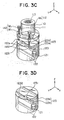
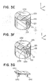
- Fig. 3A shows a specimen stage 120 of a tunnel unit in accordance with a third embodiment.
- pole pieces 122 comprise first and second pieces each having the configuration obtained by longitudinally bisecting a circular cylinder, and a third piece having the configuration of a flat plate, these first to third pieces being joined together via joint members 123.
- the first and second pieces constituting the pole pieces 122 have, in the upper portions thereof, a pair of steps opposing each other. These steps define a recess, within which the third piece is disposed. With this arrangement, therefore, two parallel parts 123a and 123b of one of the joint members 123 are exposed on a specimen placing surface 120a.
- a V-shaped groove 1231 may be formed along the one 123a of the two parallel parts exposed on the specimen placing surface 120a, with either the end portions of the two screws M1 of the associated scanning head 110 or metal spheres 1122 at the ends of these screws M1 being received within the V-shaped groove 1231, as shown in Fig. 3C.
- position determining in the Y direction shown in Fig. 3C is facilitated when the scanning head 110 is being disposed upon the specimen placing surface 120a.
- a V-shaped groove 1231 may be formed along the one 123a of the two parallel parts of the joint member 123 in such a manner as to extend to a mid portion thereof and, simultaneously, one conical groove 1232 may be formed in another portion of that one parallel part 123a, with either the end portions of the two screws M1 or the metal spheres 1122 being respectively received in the V-shaped groove 1231 and the conical groove 1232.
- Fig. 3E shows a specimen stage 120 of a tunnel unit in accordance with a fourth embodiment of the present invention.
- the specimen stage 120 has two pole pieces 122 of the same type as that shown in Fig. 1A.
- a specimen placing surface 120a of the specimen stage 120 has one streak of V-shaped groove 1231 formed therein in such a manner as to extend across one of the joint members 123 which is exposed on the specimen placing surface 120a, and one conical groove 1232 formed in that joint member 123.
- the tunnel unit is used while either the end portions or the associated metal spheres 1122 of two M1 of the screws are received within the V-shaped groove 1231 and the end portion or the associated metal sphere 1122 of the other screw M2 is received within the conical groove 1232.
- two V-shaped grooves 1231 may be formed on either side of the joint member 123 in such a manner that neither of the V-shaped grooves intersects the joint member 123 and, accordingly, no groove is formed in the center of the specimen placing surface 120a.
- Fig. 3G shows a specimen holder 1241 for holding a specimen 1241.
- the specimen holder 1241 is formed of a material having a high magnetic permeability and has a pair of legs 1242. In compliance with these legs 1242, the V-shaped grooves 1231 formed in the specimen stage 120 shown in Fig.
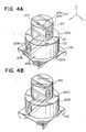
- FIG. 4A A fifth embodiment of the present invention is shown in Fig. 4A.
- an auxiliary stage 120B is provided between a specimen stage 120, such as that shown in Fig. 3B, and a unit base 130.
- the auxiliary stage 120B is similar to the specimen stage 120 shown in Fig. 1A in that the auxiliary stage 120B has a pair of second pole pieces 122B joined to each other via second joint members 123B, and a second permanent magnet 121B rotatably inserted at the joint of these second pole pieces 122B.
- the auxiliary stage 120B has a configuration forming a circular cylinder. The upper end face of the circular cylinder defines a specimen stage disposing surface 120A.
- the auxiliary stage 120B is disposed upon the unit base 130, and a specimen stage 120 is disposed upon the specimen stage disposing surface 120A of the auxiliary stage 120B.
- the specimen stage 120 is disposed in such a manner that the associated permanent magnet 121 is normal to the permanent magnet 121B of the auxiliary stage 120B.
- a scanning head 110 is disposed upon the specimen stage 120.
- the specimen stage 120 is rigidly fixed in place above the unit base 130, together with the auxiliary stage 120B . Thereafter, when the operation under [C] is performed, the scanning head 110 can be fixed to the specimen stage 120. In this way, it is possible to disassemble and reassemble the scanning head 110 alone, thereby facilitating operations such as the replacement of the probe 115 or the specimen 124.
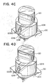
- an electrically insulating portion 120C formed of a material possessing electrically insulating and adhesive characteristics, such as an epoxy resin having a high volume resistivity, may be provided between the auxiliary stage 120B and the specimen stage 120.
- the specimen stage 120 on which specimens 124 may be placed and the unit base 130 are electrically insulated, it is possible to form a voltage circuit in which the bias voltage to be applied between the probe 115 and the specimen 124 can be easily set to either of positive and negative voltages.
- a notch 120Bb may be formed in the lower end face of the auxiliary stage 120B and along the joint of the two pole pieces 122B.
- an electrically insulating portion 120C having a magnetic permeability and electrically insulating characteristics such as a mixture of an epoxy resin which is an electrical insulator, and fine particles of a substance having a high magnetic permeability dispersed therein, may be provided at the portions of the two pole pieces 122B where they are in contact with the unit base 130.
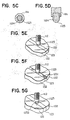
- a sixth embodiment of the present invention is shown in Fig. 5A.
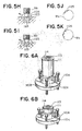
- a scanning head 110 has three screws 112 which each comprise a micrometer 112A. According to this embodiment, it is possible to vertically move the scanning head 110 while the scales of these micrometers 112A are being read. Thus, it is possible to estimate the distance between the associated probe 115 and the specimen 124 which are being brought close to each other, and to reduce the risk that the probe 115 may collide with the specimen 124. Further, if micrometers 112A provided with click-generating knobs 112B are used, as shown in Fig.
- Such a click-generating knob 112B may be achieved by providing a plurality of small steel balls around the axis of each micrometer 112A, and also providing rectangular springs in the gaps between the steel balls, thereby providing one type of a miniature ball bearing.
- a metal hemisphere 1123 may be mounted at the end 112b of the screw M2 positioned on the joint member 123 that is exposed on the specimen placing surface 120a of the specimen stage 120, the outer side of the metal hemisphere 1123 having grooves 1124, such as those recess-shaped or V-shaped, formed therein at equal intervals and extending parallel with the axis of the screw M2.
- the screw M2 having this arrangement may be rotated, as shown in Figs. 5 E to 5G, on a flat joint member 123, in a V-shaped groove 1231 formed in a joint member 123, or in a conical groove 1232 formed in a joint member 123.
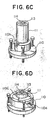
- a scanning head 110 comprises a scanning head main body 111 and a head adapter 110A, and three screws 112 are mounted on a flange 110B of the head adapter 110A.
- the scanning head main body 111 is inserted into a through hole formed in the center of the head adapter 110A and is fixed in place by stopper screws 110a.
- the scanning head main body 111 and the head adapter 110A can be easily assembled and disassembled, and the replacement of the scanning head main body 111 enables the use of circular cylindrical piezoelectric elements 113 of different lengths L.
- a collet chuck 110c may be provided between the head adapter 110A and the scanning head main body 111 so that the scanning head main body 111 is fixed in place by the collet chuck 110c.
- the assembly and disassembly of the scanning head main body 111 which is effected by opening and closing a collet chuck lever 110d, is much facilitated, and, in addition, rigid fixing can be achieved.
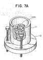
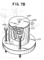
- Fig. 7A shows an eighth embodiment of the present invention.
- a scanning head main body 111 of a scanning head 110 incorporates a preamplifier 110D provided for amplifying the tunnel current from the associated probe 115.
- the tunnel unit may further include an electric shielding cover 110E provided at the upper portion of the scanning head main body 111, and a display lamp 110F, such as an LED lamp, provided on the shielding cover 110E and capable of turning off when the tunnel current flowing through the probe 115 has reached a set value.
- the display lamp 110F is adapted to turn off upon the achievement of a set value of the tunnel current, there is no risk of any electric noise being generated by the display lamp 110F during the operation of the tunnel unit.
- an absolute amplifier to which the output of a preamplifier 110D is supplied as an input signal may be incorporated within the scanning head main body 111, together with the preamplifier 110D.
- An example of an electric circuit comprising a preamplifier 110D and a display lamp 110F is shown in Fig. 7C, while an example of an electric circuit comprising a preamplifier 110D, an absolute amplifier, and a display lamp 110F is shown in Fig. 7D.
- FIG. 8A A ninth embodiment of the present invention is shown in Fig. 8A.
- an opening 111a is formed at a portion of a scanning head main body 111, thereby enabling the probe 115 and the specimen 124 to be visually observed through the opening 111a.
- an opening 111a may be formed in the scanning head main body 111 in such a manner as to completely separate two M1 of the screws 112. With this arrangement, the tip of the probe 115 can be observed more easily.
- notches 111b of a suitable depth and a suitable width are simultaneously formed between the other screw M2 and each of the two screws M1 in order to adjust the distribution of the weight of the scanning head 110, the weight of the scanning head 110 applied to the three screws 112 can be distributed with good balance.
- an illuminating lamp 110G may be provided in the vicinity of an opening 111 provided for observing the probe 115.
- the provision of the lamp 110G facilitates the observation of the probe 115.
- an illuminating lamp 110G capable of generating light within a specific range of wavelength is used, the following advantage is provided. When the light from such a lamp 110G is radiated onto the surface of a specimen 124 which is formed of a semiconductor having a low carrier density, an optically excited carrier is produced, thereby facilitating the operation of the associated STM.
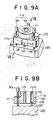
- FIG. 9A and 9B A tenth embodiment of the present invention is shown in Figs. 9A and 9B.
- an observation window body 116 is provided in an opening 111a of a scanning head main body 111 of a scanning head 110 in such a manner as to close the opening 111a.
- the opening 111a is located on one side of the scanning head main body 111 and in front of a probe 115.
- the configuration of the opening 111a is, for instance, horseshoe-shaped and defined by a semicircular arc having a radius of 6 mm and two straight lines continuing from the semicircular arc and having a length of 2 mm, and has, for instance, a depth of 7 mm.
- a piezoelectric element 113 having an outer diameter of 12 mm is used, and simultaneously if a through hole 111b of the scanning head main body 111 in which the piezoelectric element 113 is inserted has a diameter of 18 mm, the distance from the outermost end of the opening 111a to the tip of the probe 115 is approximately 10 mm.
- the observation window body 116 is formed of a material which is optically transparent and has a sound insulating property, such as boro-silicate crown glass, molten quartz glass, or synthetic quartz glass. If the scanning head 110 is to be used in a certain type of environment where the scanning head 110 will be subjected to relatively little external noise, a plastic material such as acrylic diglycol carbonate may be used.
- the observation window body 116 is formed with the same configuration as the opening 111a, and is fixed within the opening 111a by employing either a tight-fitting method or an adhesive. If the opening 111a has a configuration of certain type, threads may be formed in the outer periphery of the observation window body 116 and the inner periphery of the opening 111a in such a manner as to allow mutual engagement of these threads.
- the scanning head 110 is capable of reducing the possibility of electric noise being generated. Further, since the scanning head 110 does not have to be covered with a sound wave insulating case, the efficiency of an observation operation is enhanced.
- an observation window body 116 comprises a window main body 1160 and a magnifying lens 1161 provided in the center of the window main body 1160.
- An example which may be used as the magnifying lens 1161 is a single spherical lens having a focal length which is substantially equal to the distance between the principal plane of the magnifying lens 1161 and the tip of the probe 115, and also having a maximum possible outer diameter that can be received within the opening 111a.
- the magnifying lens 1161 may be disposed with its optical axis extending perpendicular to the Z-direction of the piezoelectric element 113.
- the magnifying lens 1161 may be disposed obliquely so as to facilitate the observation of the tip of the probe 115 and the specimen 124. If threads are formed in the outer periphery of the magnifying lens 1161 and the inner periphery of a through hole formed in the window main body 1160 to fit the magnifying lens 1161 therein, and in such a manner as to allow mutual engagement of these threads, the depth with which the magnifying lens 1161 is mounted on the window main body 1160 can be easily varied, thereby enabling the adjustment of the focal point of the magnifying lens 1161.
- the observation window body 116 has the magnifying lens 1161, the observation of the tip of the probe 115 and the specimen 124 is facilitated, and, furthermore, there is no need to prepare a separate magnifier in addition to the scanning head 110.
- An alternative arrangement may be adopted in which no window main body 1160 is used and a magnifying lens 1161 alone is mounted on the scanning head main body 111 to serve as an observation window body 116.
- the material used to form the scanning head main body 111 is a magnetic substance such as Invar or super-Invar
- permanent magnets 1162 may be impregnated in outer peripheral portions of the window main body 1160, as shown in Figs. 10C and 10D.
- the observation window body 116 is fixed within the opening 111a by utilizing the magnetic force of the permanent magnets 1162.
- Magnets having a large coercive force e,g., magnets of rare earth elements should preferably be used as the permanent magnets 1162.
- the assembly and disassembly of the observation window body 116 onto and from the scanning head main body 111 can be greatly facilitated.
- the position of the focal point of the magnifying lens 1161 can be easily varied by varying the depth with which the observation window body 116 is positioned within the opening 111a. This is advantageous in that, even when the position of the probe 115 or the specimen 124 has become slightly deviated during replacement, if the depth with which the observation window body 116 is positioned within the opening 111a is suitably adjusted, the tip of the probe 115 and the specimen 124 can be observed clearly.
- a condenser lens 1163 may be formed in a portion of the window main body 1160 which is in the periphery of the magnifying lens 1161, as shown in Figs. 10E and 10F.
- the condenser lens 1163 may be, for instance, a Fresnel lens, and in this case, the magnifying lens 1161 is provided in the center of the Fresnel lens.
- a cylindrical lens 1164 may be mounted within the opening 111a, instead of the single spherical lens 1161.
- the field of view provided is wider than that provided by the single spherical lens 1161, thereby further facilitating the observation of the tip of the probe 115, etc.
- an observation window body 116 has a window main body 1160 and an electromagnetic wave insulating shield 1165 formed on one surface of the window main body 1160.
- An example which may be used as the electromagnetic wave insulating shield 1165 is an electroconductive film such as the so-called ITO film formed of an oxide of indium and tin. Such a film is formed as the shield 1165 by coating it on the surface of the window main body 1160.
- the electromagnetic wave insulating shield 1165 is electrically connected, at its outer peripheral portion, to the scanning head main body 111 formed of a metal material, so as to shut out electromagnetic waves propagating inwardly from the outside.
- An example of a method of electrically connecting the electromagnetic wave insulating shield 1165 and the scanning head 111 is a method in which an electroconductive adhesive is applied to the interface between these members.
- electrical connection between the electromagnetic wave insulating shield 1165 and the scanning head main body 111 may be provided by using a metal frame which is in contact with the shield 1165 is mechanically fixed to the side portions of the observation window body 116 and is kept in contact with the inner periphery of the opening 111a.
- an electromagnetic wave insulating shield 1166 which is formed of meshes of an electroconductive material may be bonded to the surface of the window main body 1160.
- an arrangement such as that shown in Figs. 11E and 11F may be adopted in which the window main body 1160 is formed of a plastic material such as a polycarbonate or acrylic material, and the electromagnetic wave insulating shield 1166 is impregnated within this window main body 1160.
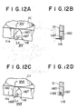
- FIG. 12A and 12B A thirteenth embodiment of the present invention is shown in Figs. 12A and 12B.
- an illuminating lamp 1167 is impregnated in a window main body 1160.
- the illuminating lamp 1167 is disposed at a position with which the observation of the probe 115 and the specimen 124 is not hindered. Since light radiated from the illuminating lamp 1167 provides brightness, this facilitates the observation of the probe 115 and the specimen 124.
- the lamp 1167 may alternatively be mounted on the surface of the window main body 1160, or be provided in such a manner that only a portion of the lamp 1167 is impregnated within the window main body 1160, with the remaining portion being exposed on the out side of the window main body 1160.
- a mirror 1168 may provided in the vicinity of the illuminating lamp 1167. With this arrangement, light from the illuminating lamp 1167 is reflected by the mirror 1168 to be shone on the probe 115 and the specimen 124, thereby achieving an increased brightness in the portion to be observed.
- a preferable example of the mirror 1168 is a mirror having a light-converging characteristic, such as a concave mirror.
- a specimen stage 120 has a recess 120b formed in the specimen placing surface 120a thereof, and a scanning head 110 is disposed in this recess 120b.
- the bottom face of the scanning head main body 111 is received within the recess 120b.
Landscapes
- Physics & Mathematics (AREA)
- Health & Medical Sciences (AREA)
- General Health & Medical Sciences (AREA)
- General Physics & Mathematics (AREA)
- Nuclear Medicine, Radiotherapy & Molecular Imaging (AREA)
- Radiology & Medical Imaging (AREA)
- Chemical & Material Sciences (AREA)
- Engineering & Computer Science (AREA)
- Nanotechnology (AREA)
- Analytical Chemistry (AREA)
- Crystallography & Structural Chemistry (AREA)
- Measurement Of Length, Angles, Or The Like Using Electric Or Magnetic Means (AREA)
Priority Applications (1)
| Application Number | Priority Date | Filing Date | Title |
|---|---|---|---|
| EP95103363A EP0664448A3 (de) | 1988-12-13 | 1989-06-20 | Tunneleinheit und Rastenkopf für ein Rastertunnelmikroskop. |
Applications Claiming Priority (4)
| Application Number | Priority Date | Filing Date | Title |
|---|---|---|---|
| JP312825/88 | 1988-12-13 | ||
| JP31282588 | 1988-12-13 | ||
| JP57809/89 | 1989-03-13 | ||
| JP1057809A JP2501897B2 (ja) | 1988-12-13 | 1989-03-13 | 走査型トンネル顕微鏡のトンネル・ユニット及びスキャン・ヘッド |
Related Child Applications (2)
| Application Number | Title | Priority Date | Filing Date |
|---|---|---|---|
| EP95103363A Division EP0664448A3 (de) | 1988-12-13 | 1989-06-20 | Tunneleinheit und Rastenkopf für ein Rastertunnelmikroskop. |
| EP95103363.8 Division-Into | 1995-03-09 |
Publications (3)
| Publication Number | Publication Date |
|---|---|
| EP0373742A2 true EP0373742A2 (de) | 1990-06-20 |
| EP0373742A3 EP0373742A3 (de) | 1991-10-02 |
| EP0373742B1 EP0373742B1 (de) | 1995-12-13 |
Family
ID=26398882
Family Applications (1)
| Application Number | Title | Priority Date | Filing Date |
|---|---|---|---|
| EP89306245A Expired - Lifetime EP0373742B1 (de) | 1988-12-13 | 1989-06-20 | Tunneleinheit und Rasterkopf für ein Tunnelrastermikroskop |
Country Status (3)
| Country | Link |
|---|---|
| US (1) | US4947042A (de) |
| EP (1) | EP0373742B1 (de) |
| DE (1) | DE68925106T2 (de) |
Cited By (7)
| Publication number | Priority date | Publication date | Assignee | Title |
|---|---|---|---|---|
| EP0529846A1 (de) * | 1991-08-08 | 1993-03-03 | Nikon Corporation | Rasterabtastmikroskop |
| EP0564088A1 (de) * | 1992-03-04 | 1993-10-06 | Topometrix | Rasterkraftmikroskop mit integrierter Optik und Auslegerhalterung |
| EP0565227A1 (de) * | 1992-03-06 | 1993-10-13 | Topometrix | Rasterkraftmikroskop |
| EP0566912A1 (de) * | 1992-04-06 | 1993-10-27 | The Perkin-Elmer Corporation | Vorrichtung zum Halten einer Elektrode durch einen magnetisch abgeschirmten Magenten |
| EP0597622A1 (de) * | 1992-11-09 | 1994-05-18 | International Business Machines Corporation | Probenträgervorrichtung für ein Rastermikroskop |
| AT519344A1 (de) * | 2016-10-18 | 2018-05-15 | Anton Paar Gmbh | Definiert schaltbare magnetische Haltevorrichtung |
| CN109863638A (zh) * | 2017-07-11 | 2019-06-07 | 株式会社Lg化学 | 用于二次电池测试的固定装置 |
Families Citing this family (28)
| Publication number | Priority date | Publication date | Assignee | Title |
|---|---|---|---|---|
| JPH02187944A (ja) * | 1989-01-13 | 1990-07-24 | Sharp Corp | 再生装置 |
| US5015850A (en) * | 1989-06-20 | 1991-05-14 | The Board Of Trustees Of The Leland Stanford Junior University | Microfabricated microscope assembly |
| US5103095A (en) * | 1990-05-23 | 1992-04-07 | Digital Instruments, Inc. | Scanning probe microscope employing adjustable tilt and unitary head |
| JP2501945B2 (ja) * | 1990-08-28 | 1996-05-29 | 三菱電機株式会社 | 原子間力顕微鏡のカンチレバ―及びその製造方法 |
| JPH0758193B2 (ja) * | 1990-09-14 | 1995-06-21 | 三菱電機株式会社 | 原子間力顕微鏡の微動走査機構 |
| JP2744346B2 (ja) * | 1990-10-19 | 1998-04-28 | キヤノン株式会社 | 情報記録ユニットと情報記録及び/又は再生装置と情報記録及び/又は再生方法と情報記録媒体 |
| US5155361A (en) * | 1991-07-26 | 1992-10-13 | The Arizona Board Of Regents, A Body Corporate Acting For And On Behalf Of Arizona State University | Potentiostatic preparation of molecular adsorbates for scanning probe microscopy |
| JP2598851B2 (ja) * | 1992-01-23 | 1997-04-09 | 松下電器産業株式会社 | 位置決め装置 |
| US5448399A (en) | 1992-03-13 | 1995-09-05 | Park Scientific Instruments | Optical system for scanning microscope |
| JPH07122218A (ja) * | 1993-10-26 | 1995-05-12 | Ryoden Semiconductor Syst Eng Kk | 走査プローブ顕微鏡ヘッドの試料台 |
| US5440920A (en) * | 1994-02-03 | 1995-08-15 | Molecular Imaging Systems | Scanning force microscope with beam tracking lens |
| US5515719A (en) * | 1994-05-19 | 1996-05-14 | Molecular Imaging Corporation | Controlled force microscope for operation in liquids |
| US5513518A (en) * | 1994-05-19 | 1996-05-07 | Molecular Imaging Corporation | Magnetic modulation of force sensor for AC detection in an atomic force microscope |
| US5753814A (en) * | 1994-05-19 | 1998-05-19 | Molecular Imaging Corporation | Magnetically-oscillated probe microscope for operation in liquids |
| US5866805A (en) * | 1994-05-19 | 1999-02-02 | Molecular Imaging Corporation Arizona Board Of Regents | Cantilevers for a magnetically driven atomic force microscope |
| EP0783662B1 (de) * | 1994-08-27 | 1999-04-07 | International Business Machines Corporation | Feineinstellungsapparat mit atomarer auflösung |
| US5621210A (en) * | 1995-02-10 | 1997-04-15 | Molecular Imaging Corporation | Microscope for force and tunneling microscopy in liquids |
| US5750989A (en) * | 1995-02-10 | 1998-05-12 | Molecular Imaging Corporation | Scanning probe microscope for use in fluids |
| US5675154A (en) * | 1995-02-10 | 1997-10-07 | Molecular Imaging Corporation | Scanning probe microscope |
| US5569918A (en) * | 1995-03-17 | 1996-10-29 | Rhk Technology, Inc. | Probe holder and probe mounting method for a scanning probe microscope |
| US5821545A (en) * | 1995-11-07 | 1998-10-13 | Molecular Imaging Corporation | Heated stage for a scanning probe microscope |
| US5654546A (en) * | 1995-11-07 | 1997-08-05 | Molecular Imaging Corporation | Variable temperature scanning probe microscope based on a peltier device |
| JP3390318B2 (ja) * | 1996-02-13 | 2003-03-24 | セイコーインスツルメンツ株式会社 | 微小位置決め機構及びそれを用いた走査型プローブ顕微鏡及び微小領域加工機 |
| US6076397A (en) * | 1997-12-01 | 2000-06-20 | International Business Machines Corporation | Positioning apparatus |
| JP3788573B2 (ja) * | 2000-11-16 | 2006-06-21 | 信越化学工業株式会社 | Mri用磁気回路の組立方法 |
| JP5728162B2 (ja) * | 2010-03-30 | 2015-06-03 | 株式会社メルビル | 試料ホルダー、及び試料駆動装置 |
| CN105092899B (zh) * | 2015-08-25 | 2018-06-29 | 中国科学院物理研究所 | 一种支架定位装置 |
| CN105791621B (zh) * | 2016-04-29 | 2018-08-31 | 安徽宝葫芦信息科技集团股份有限公司 | 一种文档扫描机的扫描头快速固定装置 |
Family Cites Families (2)
| Publication number | Priority date | Publication date | Assignee | Title |
|---|---|---|---|---|
| US4914293A (en) * | 1988-03-04 | 1990-04-03 | Kabushiki Kaisha Toshiba | Microscope apparatus |
| JP2572107B2 (ja) * | 1988-04-04 | 1997-01-16 | 三菱電機株式会社 | 走査型トンネル顕微鏡の粗動機構 |
-
1989
- 1989-06-14 US US07/366,175 patent/US4947042A/en not_active Expired - Fee Related
- 1989-06-20 EP EP89306245A patent/EP0373742B1/de not_active Expired - Lifetime
- 1989-06-20 DE DE68925106T patent/DE68925106T2/de not_active Expired - Fee Related
Cited By (10)
| Publication number | Priority date | Publication date | Assignee | Title |
|---|---|---|---|---|
| EP0529846A1 (de) * | 1991-08-08 | 1993-03-03 | Nikon Corporation | Rasterabtastmikroskop |
| US5317153A (en) * | 1991-08-08 | 1994-05-31 | Nikon Corporation | Scanning probe microscope |
| EP0564088A1 (de) * | 1992-03-04 | 1993-10-06 | Topometrix | Rasterkraftmikroskop mit integrierter Optik und Auslegerhalterung |
| EP0565227A1 (de) * | 1992-03-06 | 1993-10-13 | Topometrix | Rasterkraftmikroskop |
| EP0566912A1 (de) * | 1992-04-06 | 1993-10-27 | The Perkin-Elmer Corporation | Vorrichtung zum Halten einer Elektrode durch einen magnetisch abgeschirmten Magenten |
| EP0597622A1 (de) * | 1992-11-09 | 1994-05-18 | International Business Machines Corporation | Probenträgervorrichtung für ein Rastermikroskop |
| AT519344A1 (de) * | 2016-10-18 | 2018-05-15 | Anton Paar Gmbh | Definiert schaltbare magnetische Haltevorrichtung |
| US10330698B2 (en) | 2016-10-18 | 2019-06-25 | Anton Paar Gmbh | Definably switchable magnetic holding device |
| AT519344B1 (de) * | 2016-10-18 | 2019-11-15 | Anton Paar Gmbh | Definiert schaltbare magnetische Haltevorrichtung |
| CN109863638A (zh) * | 2017-07-11 | 2019-06-07 | 株式会社Lg化学 | 用于二次电池测试的固定装置 |
Also Published As
| Publication number | Publication date |
|---|---|
| EP0373742B1 (de) | 1995-12-13 |
| DE68925106D1 (de) | 1996-01-25 |
| US4947042A (en) | 1990-08-07 |
| EP0373742A3 (de) | 1991-10-02 |
| DE68925106T2 (de) | 1996-08-22 |
Similar Documents
| Publication | Publication Date | Title |
|---|---|---|
| US4947042A (en) | Tunnel unit and scanning head for scanning tunneling microscope | |
| US5107114A (en) | Fine scanning mechanism for atomic force microscope | |
| EP0862045B1 (de) | Atomkraftmikroskop mit nach Wahl auswechselbarer Flüssigkeitszelle | |
| US5468959A (en) | Scanning probe microscope and method for measuring surfaces by using this microscope | |
| EP0866341B1 (de) | Wechselstrom Magnetkraftmikroskop mit integriertem Spulkopf | |
| US6636050B2 (en) | Four-terminal measuring device that uses nanotube terminals | |
| US4837445A (en) | Coarse adjusting device of scanning tunneling microscope | |
| US6121771A (en) | Magnetic force microscopy probe with bar magnet tip | |
| US5602330A (en) | Non-contact force microscope having a coaxial cantilever-tip configuration | |
| JP2501897B2 (ja) | 走査型トンネル顕微鏡のトンネル・ユニット及びスキャン・ヘッド | |
| Van Kempen et al. | Applications of a high-stability scanning tunneling microscope | |
| JPH06249933A (ja) | 磁気力顕微鏡用カンチレバー | |
| JP2000346786A (ja) | 高性能ナノチューブプローブ | |
| JP2001021478A (ja) | 走査プローブ顕微鏡用探針、その製造法および描画装置 | |
| US6476386B1 (en) | Method and device for tunnel microscopy | |
| JPH07113634A (ja) | 走査型探針顕微鏡用探針、その製造方法、当該探針を用いた記録再生装置及び微細加工装置 | |
| JP3428403B2 (ja) | フリクション・フォース・プローブ顕微鏡およびフリクション・フォース・プローブ顕微鏡を用いた原子種や材料の同定方法 | |
| JPH04162339A (ja) | 表面観察装置用探針の製造方法及び表面観察装置 | |
| JPH0783942A (ja) | 走査型探針顕微鏡用探針、その製造方法、当該探針を用いた記録再生装置及び微細加工装置 | |
| JPH0549921B2 (de) | ||
| JPH0616410B2 (ja) | 透過型電子顕微鏡用走査トンネル顕微鏡 | |
| JPH0690006B2 (ja) | 走査トンネル顕微鏡を備えた透過型電子顕微鏡 | |
| JP3727810B2 (ja) | 電子顕微鏡装置内における微小物作成方法及びその装置 | |
| JP2997497B2 (ja) | 磁気情報検出装置 | |
| CA2031733C (en) | Method for forming probe and apparatus therefor |
Legal Events
| Date | Code | Title | Description |
|---|---|---|---|
| PUAI | Public reference made under article 153(3) epc to a published international application that has entered the european phase |
Free format text: ORIGINAL CODE: 0009012 |
|
| AK | Designated contracting states |
Kind code of ref document: A2 Designated state(s): DE FR GB |
|
| 17P | Request for examination filed |
Effective date: 19901210 |
|
| PUAL | Search report despatched |
Free format text: ORIGINAL CODE: 0009013 |
|
| AK | Designated contracting states |
Kind code of ref document: A3 Designated state(s): DE FR GB |
|
| 17Q | First examination report despatched |
Effective date: 19940520 |
|
| GRAA | (expected) grant |
Free format text: ORIGINAL CODE: 0009210 |
|
| AK | Designated contracting states |
Kind code of ref document: B1 Designated state(s): DE FR GB |
|
| XX | Miscellaneous (additional remarks) |
Free format text: TEILANMELDUNG 95103363.8 EINGEREICHT AM 20/06/89. |
|
| REF | Corresponds to: |
Ref document number: 68925106 Country of ref document: DE Date of ref document: 19960125 |
|
| REG | Reference to a national code |
Ref country code: GB Ref legal event code: 727 |
|
| ET | Fr: translation filed | ||
| REG | Reference to a national code |
Ref country code: GB Ref legal event code: 727A |
|
| REG | Reference to a national code |
Ref country code: GB Ref legal event code: 727B |
|
| PLBE | No opposition filed within time limit |
Free format text: ORIGINAL CODE: 0009261 |
|
| STAA | Information on the status of an ep patent application or granted ep patent |
Free format text: STATUS: NO OPPOSITION FILED WITHIN TIME LIMIT |
|
| REG | Reference to a national code |
Ref country code: GB Ref legal event code: SP |
|
| 26N | No opposition filed | ||
| PGFP | Annual fee paid to national office [announced via postgrant information from national office to epo] |
Ref country code: FR Payment date: 19980609 Year of fee payment: 10 |
|
| PGFP | Annual fee paid to national office [announced via postgrant information from national office to epo] |
Ref country code: GB Payment date: 19980611 Year of fee payment: 10 |
|
| PGFP | Annual fee paid to national office [announced via postgrant information from national office to epo] |
Ref country code: DE Payment date: 19980629 Year of fee payment: 10 |
|
| PG25 | Lapsed in a contracting state [announced via postgrant information from national office to epo] |
Ref country code: GB Free format text: LAPSE BECAUSE OF NON-PAYMENT OF DUE FEES Effective date: 19990620 |
|
| PG25 | Lapsed in a contracting state [announced via postgrant information from national office to epo] |
Ref country code: FR Free format text: THE PATENT HAS BEEN ANNULLED BY A DECISION OF A NATIONAL AUTHORITY Effective date: 19990630 |
|
| GBPC | Gb: european patent ceased through non-payment of renewal fee |
Effective date: 19990620 |
|
| PG25 | Lapsed in a contracting state [announced via postgrant information from national office to epo] |
Ref country code: DE Free format text: LAPSE BECAUSE OF NON-PAYMENT OF DUE FEES Effective date: 20000503 |
|
| REG | Reference to a national code |
Ref country code: FR Ref legal event code: ST |