EP0373932A2 - Wärmefixiervorrichtung mit Gasreinigungsmitteln - Google Patents
Wärmefixiervorrichtung mit Gasreinigungsmitteln Download PDFInfo
- Publication number
- EP0373932A2 EP0373932A2 EP89313077A EP89313077A EP0373932A2 EP 0373932 A2 EP0373932 A2 EP 0373932A2 EP 89313077 A EP89313077 A EP 89313077A EP 89313077 A EP89313077 A EP 89313077A EP 0373932 A2 EP0373932 A2 EP 0373932A2
- Authority
- EP
- European Patent Office
- Prior art keywords
- sheet
- fixing unit
- thermal fixing
- filter
- main frame
- Prior art date
- Legal status (The legal status is an assumption and is not a legal conclusion. Google has not performed a legal analysis and makes no representation as to the accuracy of the status listed.)
- Withdrawn
Links
Images



Classifications
-
- G—PHYSICS
- G03—PHOTOGRAPHY; CINEMATOGRAPHY; ANALOGOUS TECHNIQUES USING WAVES OTHER THAN OPTICAL WAVES; ELECTROGRAPHY; HOLOGRAPHY
- G03F—PHOTOMECHANICAL PRODUCTION OF TEXTURED OR PATTERNED SURFACES, e.g. FOR PRINTING, FOR PROCESSING OF SEMICONDUCTOR DEVICES; MATERIALS THEREFOR; ORIGINALS THEREFOR; APPARATUS SPECIALLY ADAPTED THEREFOR
- G03F7/00—Photomechanical, e.g. photolithographic, production of textured or patterned surfaces, e.g. printing surfaces; Materials therefor, e.g. comprising photoresists; Apparatus specially adapted therefor
- G03F7/002—Photomechanical, e.g. photolithographic, production of textured or patterned surfaces, e.g. printing surfaces; Materials therefor, e.g. comprising photoresists; Apparatus specially adapted therefor using materials containing microcapsules; Preparing or processing such materials, e.g. by pressure; Devices or apparatus specially designed therefor
- G03F7/0022—Devices or apparatus
- G03F7/0032—Devices or apparatus characterised by heat providing or glossing means
-
- G—PHYSICS
- G03—PHOTOGRAPHY; CINEMATOGRAPHY; ANALOGOUS TECHNIQUES USING WAVES OTHER THAN OPTICAL WAVES; ELECTROGRAPHY; HOLOGRAPHY
- G03B—APPARATUS OR ARRANGEMENTS FOR TAKING PHOTOGRAPHS OR FOR PROJECTING OR VIEWING THEM; APPARATUS OR ARRANGEMENTS EMPLOYING ANALOGOUS TECHNIQUES USING WAVES OTHER THAN OPTICAL WAVES; ACCESSORIES THEREFOR
- G03B27/00—Photographic printing apparatus
- G03B27/32—Projection printing apparatus, e.g. enlarger, copying camera
-
- G—PHYSICS
- G03—PHOTOGRAPHY; CINEMATOGRAPHY; ANALOGOUS TECHNIQUES USING WAVES OTHER THAN OPTICAL WAVES; ELECTROGRAPHY; HOLOGRAPHY
- G03D—APPARATUS FOR PROCESSING EXPOSED PHOTOGRAPHIC MATERIALS; ACCESSORIES THEREFOR
- G03D13/00—Processing apparatus or accessories therefor, not covered by groups G11B3/00 - G11B11/00
- G03D13/002—Heat development apparatus, e.g. Kalvar
-
- G—PHYSICS
- G03—PHOTOGRAPHY; CINEMATOGRAPHY; ANALOGOUS TECHNIQUES USING WAVES OTHER THAN OPTICAL WAVES; ELECTROGRAPHY; HOLOGRAPHY
- G03B—APPARATUS OR ARRANGEMENTS FOR TAKING PHOTOGRAPHS OR FOR PROJECTING OR VIEWING THEM; APPARATUS OR ARRANGEMENTS EMPLOYING ANALOGOUS TECHNIQUES USING WAVES OTHER THAN OPTICAL WAVES; ACCESSORIES THEREFOR
- G03B2227/00—Photographic printing apparatus
- G03B2227/32—Projection printing apparatus, e.g. enlarging apparatus, copying camera
- G03B2227/325—Microcapsule copiers
Definitions
- the present invention relates to a thermal fixing unit for fixing an image provided on a sheet, and more particularly, the invention relates to the thermal fixing unit for use in a copying machine in which a latent image formed on a photosensitive pressure sensitive sheet is visualized in a developer sheet medium.
- a photosensitive pressure sensitive recording medium carrying thereon a latent image is superposed with a developer sheet medium, and these mediums are pressed together for providing a chromogenic reaction upon rupture of microcapsules on the photosensitive medium.
- a visible image is formed on the developer sheet medium which is then heated by a heat roller etc. for fixing the output image during travel of the developer medium.
- gaseous substance may be released from the developer sheet upon heating, and the gas is discharged out of the heating unit.
- gas has uncomfortable smell.
- means are provided to remove the above-described gaseous component released from a heated developer sheet for providing a clean ambient condition around a thermal fixing unit.
- Preferred aspects of the invention allow one to reduce power consumption which power is required for initial start up period of the thermal fixing unit, and for mode changing phase for changing temperature mode within the thermal fixing unit, to provide a detection means in the gas purification means in order to detect service life of a filter used therein to provide means for detecting existence of the filter and alarming means which notifies an operator of non-existence of the filter in the gas purification means.
- the invention provides a thermal fixing unit for thermally fixing an output image recorded on an image recording medium, the image recording medium including a developer sheet comprising a base substrate and a developer material coated therefore, the output image being formed by a chromogenic reaction between the developer material and a chromogenic material selectively formed on a separate photosensitive sheet
- the thermal fixing unit comprising: a main frame provided with a sheet inlet and sheet outlet and defining a sheet path therebetween, a transferring means disposed within the main frame for transferring the developer sheet along the sheet path, a heating means disposed within the main frame for heating the developer sheet transferred along the sheet path, the developer sheet releasing gaseous component upon heating, and gas purification means connected to the main frame for removing the gaseous component.
- a machine frame 1 has an upper portion provided with an original support glass plate 2 for mounting thereon an original, and a cover 3 for opening and closing the original support glass plate 2.
- the glass plate 2 and the cover 3 are movable in a horizontal direction.
- a light source 6 including a halogen lamp 4 and a reflector 5 is provided below the original support glass plate 2.
- the halogen lamp 4 is adapted for irradiating light to the original on the glass plate 2 and extends in a direction perpendicular to the moving direction of the original support glass plate 2.
- the reflector 5 is adapted to direct light from the halogen lamp 4 to the original support glass plate 2.
- the original support glass plate 2 is moved in horizontal direction, so that an entire area of the original is subjected to light irradiation.
- An exposure stand 7 is disposed at an internal central portion of the machine frame 1. Further, a filter 8 for a color tone control and a focusing lens unit 9 are positioned between the light source 6 and the exposure stand 7. These filter 8 and the lens unit 9 are supported by an attachment plate 10. A pair of reflection mirrors 11 are positioned between the lens unit 9 and the exposure stand 7 for adjusting a light path length and focal length. These reflection mirrors 11 are movably supported on an attachment member 12. A light from the light source 6 is reflected at the original and is directed toward the exposure stand 7 through the filter 8, the lens unit 9 and the reflection mirrors 11.
- a sheet cartridge 14 is detachably provided at an upper internal space of the machine frame 1.
- an elongated web-like photosensitive sheet 13 is installed in a rolled state.
- a microcapsule sheet used as the photosensitive sheet is a microcapsule sheet in which a plurality of microcapsules are formed which encapsulate therein chromogenic material or dye precursor.
- a plurality of feed rollers 16 are rotatably provided for guide travel of the microcapsule sheet 13.
- the microcapsule sheet 13 drawn out of the sheet cartridge 14 is wound over the takeup shaft 15 by means of feed rollers 16. During the travel of the sheet 13, it passes along a lower surface of the exposure stand 7 at which the sheet 13 is exposed to light for forming a latent image thereon corresponding to an image of the original.
- a sheet cassette 18 is detachably provided at a lower inner portion of the machine frame 1 and below the exposure stand 7.
- the cassette 18 is adapted for storing a stack of cut developer sheets 17 each having predetermined size.
- the developer sheet 17 may includes a substrate formed of a transparent plastic film for use in an overhead projector.
- a pressure developing unit 19 is disposed at a position between the exposure stand 7 and the takeup shaft 15.
- the pressure developing unit 19 the light-exposed portion of the microcapsule sheet 13 superposed with one of the developer sheets 17 is pressed so that the non-light exposed microcapsules are ruptured to provide a chromogenic reaction with developer material formed on the developer sheet 17.
- a color output image is provided on the developer sheet 17.
- the sheet cassette 18 is provided with a protrusion 18a which identifies a size of the sheet to be accommodated in the cassette.
- a machine frame 1 is provided with a detecting means 20 which detects the protrusion 18a so as to determine the sheet size.
- a sector roller 21 is positioned above the cassette 18 for feeding each one of the developer sheet 17. Further, a plurality of feed rollers 21 and a sheet guide 25 are provided between the sheet cassette 18 and the pressure developing unit 19 for transferring the developer sheet 17 from the cassette 18 to the developing unit 19.
- a separation roller 22 is provided for separating the developer sheet 17 from the microcapsule sheet 13.
- a thermal fixing unit 23 is disposed at a position downstream of the pressure developing unit 19 for thermally fixing an output image provided on the developer sheet 17.
- a discharge tray 24 is provided at an extreme end portion of a developer sheet path for receiving the developer sheet 17 which has been subjected to thermal fixing treatment in the thermal fixing unit 23.
- the thermal fixing unit 23 includes a main body 39. Further, a hollow supporting frame 42 and a duct 44 are provided, those being described in detail with reference to Fig. 2.
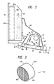
- Fig. 2 shows a thermal fixing unit provided with a gas purification means according to a first embodiment of this invention.
- the thermal fixing unit 23 includes a guide plate 31 formed of iron which defines the developer sheet path.
- the guide plate 31 is provided with a sheet passing detection switch (not shown) which generates a signal indicative of the complete discharge of the developer sheet 17 out of a sheet outlet 38 described later.
- a feed-in rollers 32 and feed- out rollers 33 are rotatably provided at inlet and outlet sides of the guide plate 31, respectively. These rollers extend in a direction perpendicular to the running direction of the developer sheet 17. Upon rotations of these rollers, the developer sheet 17 is moved along the guide plate 31.
- a casing member 35 formed with a downwardly directed opening and a shielding plate 35a secured to the opening.
- the shielding plate 35a is of a metallic mesh form, and the plate 35a and the casing member 35 define an internal space S.
- a heater 34 is positioned which is in the form of a coil element made of Nichrome line. Upon electrical power supply to the heater, ambient air is heated by the heater 34, and the heated air can pass through the meshes of the shielding plate 35a.
- a fan 36 such as a cross-flow fan is positioned within the space and at the inlet side.
- the cross-flow fan 36 has a rotation axis extending in a direction perpendicular to the sheet path.
- air in the casing 35 and heated by the heater 34 is circulated as shown by an arrow in Fig. 2.
- a sheet inlet 37 and the sheet outlet 38 are defined at positions inwardly of the feed-in rollers 32 and the feed-out rollers 33. Further, heat insulation rollers 32a and 33a are rotatably provided.
- the roller 32a is adapted to close sheet inlet 37 and is positioned between the feed-in rollers 32 and the sheet inlet 37
- the roller 33a is adapted to close the sheet outlet 38 and is positioned between the feed-out rollers 33 and the sheet outlet 38.
- the casing member 35 and the guide plate 31 constitute in combination the main body 39 of the thermal fixing unit 23.
- a cover member 41 is disposed over an entire area of the main body 39.
- the cover member 41 and the main body 39 define an air passage 40 therebetween which is also in fluid communication with the sheet inlet 37 and the sheet outlet 38.
- the hollow supporting frame 42 is installed at a position above the main body 39 and within the machine frame 1.
- a gas venting fan 43 is rotatably supported for sucking a gas released from the developer sheet 17 which gas is generated upon heating the sheet 17.
- a duct 44 is provided between the cover member 41 and an intake side of the gas venting fan 43, so that the fan 43 is in fluid communication with the interior of the thermal fixing unit through the air passage 40.
- a filter 45 is disposed within the supporting frame 42 and at a position between the gas venting fan 43 and an exhaust port (not shown).
- the gas venting fan 43 and the filter 45 constitute in combination a gas sucking means or gas purification means.
- the filter member 45 is best shown in Fig. 3 which includes an outer cylindrical frame 451, metallic meshes 452 and 453 disposed at open ends of the outer cylindrical frame 451 and a deodorizing agent 454 accommodated between the metallic meshes 452 and 453.
- One of the metallic meshes 452 confronts the gas venting fan 43, whereas other mesh 453 is in fluid communication with an atmosphere.
- a paper having high gas venting characteristic is provided on an inner surface of each of the metallic meshes and the deodorizer 454 is positioned between the papers. Even if the developer material is of the type which releases odor upon heating the developer sheet 17, the odor component is absorbed by the deodorizing agent 454.
- the filter 45 contains activated charcoal.
- An outer peripheral surface of the filter 45 is provided with a sealing member (not shown) for sealingly securing the same to the supporting frame 42.
- the copying machine which incorporates the first embodiment of this invention is provided with a microcomputer 51 as shown in Fig. 4.
- the microcomputer 51 is connected, through an input/output interface 53, to a start switch 52 which generates output signal indicative of the machine start. Further, the microcomputer 51 is connected, through the input/output interface 53, to a mode selection switch 45.
- the mode selection switch 45 Upon manipulation of the mode selection switch 45, selected is one heating mode among three kinds of heating modes which provide heating temperature different from one another.
- the three modes are low gloss mode with providing a heating temperature of 135°C, high gloss mode with providing a heating temperature of 145°C, and OHP (over head projector) mode with providing a heating temperature of 160°C.
- One of the low gloss mode and the high gloss mode are selected so as to generate difference in gloss degree in copying with using an ordinary developer sheet 17, whereas the OHP mode is selected when using the OHP sheet coated with the developer material.
- a thermistor 55 is provided at an internal surface of the casing body 55, and as shown in Fig. 4, the microcomputer 51 is connected, through the input/output interface 53, to the thermistor 55 which generates a signal indicative of the temperature in the main body 39, the signal being inputted into the microcomputer 51. Further, the heater 34, the air blowing fan 36 and the gas venting fan 43 are connected to the microcomputer 51 through the input/output interface 53.
- the microcomputer upon depression of a power switch, the microcomputer operates the heater 34 and the blower 36 in accordance with one specific mode selected by the mode selection switch 45, so that the temperature within the main body 39 is elevated.
- the heater 34 is subjected to ON/OFF control by the microcomputer 51 so as to maintain a constant temperature within the main body 39 in accordance with the selected specific mode.
- the gas venting fan 43 is rendered non-operative state by the microcomputer 51 to provide efficient temperature elevation within the main body 39, otherwise, the heated air is sucked by the gas venting fan 43 to prevent temperature from being increased.
- the microcomputer 51 operates an original moving mechanism (not shown) so that the original support glass plate 2 is horizontally moved in one direction (rightwardly in Fig. 1).
- the sector rollers 21 is operated for delivering one developer sheet 17 toward the inlet portion of the pressure developing unit 19.
- the one edge (left edge in Fig. 1) of the original reaches a position confronting the linear halogen lamp 4 of the light source 6, the halogen lamp 4 is lighted by the microcomputer 51, and the original support glass plate 2 is moved in opposite direction (leftwardly in Fig. 1) for a linear light irradiation to the original during its travel.
- the takeup shaft 15 is rotated about its axis by the microcomputer 51 for moving the microcapsule sheet 13 toward the takeup shaft 15 at a traveling speed equal to the moving speed of the original support glass plate 2.
- the microcapsule sheet 13 is exposed to light reflected from the original at the exposure stand 7, so that a latent image corresponding to the image of the original is successively formed on the microcapsule sheet 13.
- the leading edge portion of the light exposed region of the microcapsule sheet 13 is brought into alignment with the leading edge of the developer sheet17 because of the rotational motion of the takeup shaft 15, these sheets 13 and 17 are transferred to the pressure developing unit 19.
- the light exposed region of the microcapsule sheet 13 is pressed against the developer sheet 17, so that a color output image is provided on the developer sheet 17.
- the microcapsule sheet 13 is separated from the developer sheet 17 by the separation roller 22, and the developer sheet 17 is solely entered into the thermal fixing unit 23.
- the operations of the cross-flow fan 36 and the heater 34 are controlled by the microcomputer 51 for circulating hot air within the main body 39. Therefore, the colored output image on the developer sheet 17 is fixed, and the developer sheet 17 is then discharged onto the discharge tray 24.
- the rotation of the gas venting fan 43 is started by the microcomputer 51 at a proper timing prior to the entry of the developer sheet 17 into the thermal fixing unit 23.
- the rotation of the gas venting fan 43 is stopped by the microcomputer 51 when the latter acknowledges the complete discharge of the developer sheet 17 out of the sheet outlet 38, which acknowledgement is made in accordance with the output signal sent from the sheet passing detection switch (not shown) provided in the guide plate 51 to the microcomputer 51.
- the air within the main body 39 is introduced into the filter member 45 through the inlet 37, the outlet 38, the air passage 40 and the duct 44, and is discharged to the atmosphere through the discharge port (not shown) in the supporting frame 42. Therefore, odor and any components released from the develop er sheet 17 upon heating is trapped by the filter 45, and purified air is discharged outside through the discharge port.
- the heater 34 is rendered OFF by the microcomputer 51 by a predetermined time interval, and at the same time, the gas venting fan 43 is rendered ON by the microcomputer 51. Therefore, heat accumulated within the main body 39 can be released by the rotation of the gas venting fan 43, and accordingly, reduced is the time period for obtaining the selected temperature decreasing mode.
- the heater 34 is rendered ON and the gas venting fan 43 is rendered OFF by a predetermined time period in the mode switching operation. Therefore, heat escape from the main body 39 can be prevented, to thereby reduce the time period for obtaining the selected temperature increasing mode.
- odors etc. released from the heated developer sheet can be trapped by the filter 45, and the operation of the gas venting fan 43 is controlled in accordance with the start-up period of the thermal fixing unit and with the mode changing phase, to thus reduce time period for obtaining the desired temperature within the main body 39. Consequently, prompt and smooth start-up operation and mode changing operation result. Particularly, in case of the start-up period and the mode changing timing for changing the low temperature mode to the high temperature mode, excessive power consumption is avoidable because of the inoperative state of the gas venting fan.
- the filter 45 according to the first embodiment is positioned within the machine frame 1. However, corresponding filter can be disposed outside the machine frame 1, and instead, the gas venting fan 43 is solely disposed within the machine frame. Further, in the first embodiment, three kinds of temperature modes are provided. However, the mode numbers can be increased or decreased, and the embodiment shown in Fig. 2 is also available for a monochromatic copying machine.
- the gas purification means including the filter member, and therefore, odors etc. released from the heated developer sheet can be trapped by the purification means, to thereby provide a comfortable working condition for the workers.
- the gas sucking operation is suspended at the initial start-up period of the thermal fixing unit, to thereby rapidly provide the elevated temperature within the main body capable of providing the thermally fixable condition with eliminating excessive power consumption.
- the gas purification means is efficiently utilized for promptly providing a variety of operation modes having temperatures within the thermal fixing unit different from one another depending upon the kinds of the developer sheets to be used.
- a second embodiment according to the present invention will next be described with reference to Fig. 5.
- the second embodiment employs a microcomputer 51A provided with a non-volatile memory 51a. Further, a display 61 is connected to an input/output interface 53. Remaining circuitry connection would be the same as those of the first embodiment shown in Fig. 4.
- These non-volatile memory 51a and the display 61 serve as means for detecting service life of the filter, and means for displaying unavailable state of the filter.
- the non-volatile memory 51a has a storage location in which total copying numbers are stored. Further, the display 61 will notify the operator of the replacement of the filter element 45 when the filter is unavailable for trapping the odor and any components therein. More specifically, when the start switch 52 is operated, the microcomputer 51A increments the copying numbers stored in the non-volatile memory 51a. If the copying numbers exceed the predetermined numbers, the microcomputer 51A sends signal to the display 61 for notifying the operator of the necessity of changing the filter with a new one. At the same time, the microcomputer 51A is rendered in standby state. In the standby state, the copying machine will not be operated even by the operation of the start switch 52. When the display 61 notifies the filter change, the operator must exchange the filter with the new one. Upon completion of the filter replacement, the total copying numbers stored in the non-volatile memory 51a is cleared.
- gas detecting means can be used for detecting the specific component of the gas. That is, if the filter 43 is not any more be available for trapping the specific components, the density of the component within the gas becomes increased. Therefore, the rate of the amounts of the components at the downstream side of the filter to that at the upstream side thereof is measured for finally detecting the service life of the filter.
- the operator can notify the replacement timing of the filter, and the copying machine becomes inoperable state when the filter 45 becomes unavailable for trapping the odors etc. Therefore, disadvantageous discharge of the odor etc from the copying machine can be obviated, and at the same time, the gas purification means can always be operated with the available conditions of the filter.
- the second embodiment is particularly useful when installing the copying machine on an office in which unspecified persons may use the copying machine who cannot recognize optimum filter exchanging timing unless provided are means for detecting the service life of the filter and means for displaying the unavailability of the filter.
- a microcomputer 51B is so arranged to provide means for computing a temperature elevation rate, means for determining the rate, and alarming means.
- the means for computing a temperature elevation rate and the determining means serve as means for determining existence of the filter 45. That is, similar to the foregoing embodiments, a thermistor 55 is provided within the main body 39 so as to generate detection signal indicative of the temperature within the main body 39. The signal from the thermistor 55 is supplied to the microcomputer 51B in order to determine the temperature elevation ratio. As shown in Fig.
- the temperature within the main body 39 can be rapidly increased as shown in a solid line A, so that desirable elevated temperature such as 130° C in the low gloss mode can be promptly obtained, even though the filter allow restricted amount of air to pass therethrough.
- the temperature within the main body 39 cannot be promptly increased as shown in a dotted chain line B due to the free air leakage through the discharge port. If the temperature increasing ratio is lower than a predetermined ratio stored in the microcomputer 51B, the determination means determines that no filter is provided, and the result of the determination is displayed by the alarming means.
- step S1 Upon depression of a power switch (not shown), the heater 34 and the fan 36 are operated so as to elevate a temperature within the main body 39. Further, the gas venting fan 43 is also operated to start gas ventilation.
- step S2 determination is made whether or not a predetermined time period, for example 3 minutes, has passed. If YES, a routine proceeds into step S4 where determination is made as to whether or not the temperature reaches a predetermined temperature such as 130°C. If the temperature exceeds this temperature, the routine proceeds into step S5 where an ordinary processing is carried out, and the routine is terminated at step S7.
- a predetermined time period for example 3 minutes
- step S4 if the temperature does not reach the predetermined temperature, the routine returns to step S6 where an error signal is generated with lighting a display lamp 56. Therefore, an operator can notify any abnormality in the copying machine and necessity of effecting maintenance thereto. Then, routine proceeds into step S7 where the operations of the heater 34, the fan 36 and the gas venting fan 43 are stopped.
- step S2 if the predetermined time period has not been passed the routine returns to step S3 where determination is made as to whether or not the temperature elevation ratio is less than the predetermined ratio. That is, this determination can be effected on a basis of the inclination angles shown in Fig. 8. If NO (the ratio is not less than the predetermined ratio), the routine returns to the step S2. On the other hand, if YES (the rate is less than the predetermined ratio), the routine proceeds into the step S6 for alarming and into S7 so as to stop operations of the heater 34, the fan 36 and the gas venting fan 43. There fore, an operator can notify that no filter 43 is assembled in the gas purification means.
- the start switch 52 is operated so that the color copying operation such as exposure, pressure developing and thermal fixing operations are successively performed in a manner similar to those described in the foregoing embodiments.
- the temperature in the thermal fixing unit 23 at a position upstream of the deodorization filter 45 is detected by the thermistor 55, and existence of the filter 45 can be determined by the temperature elevation rate computed by the signal from the thermistor 55. If the filter 45 is not assembled, the operations of the heater 34, the hot air circulating fan 36 and the gas venting fan 43 can be stopped, to thereby minimize power consumption. Further, if the deodorization filter 45 is not provided, the display lamp 56 is lighted, so that an operator can notify this fact. Therefore, a new filter can surely be assembled into the gas purification means after removal of the old filter.
- the thermistor 55 which mainly serves to control the temperature within the thermal fixing unit 23 during the color copying operation is used for the purpose of detecting the existence of the deodorization filter 45. Accordingly, another particular detection device such as a temperature sensor or a limit switch can be dispensed with for detecting the existence of the filter 45. Consequently, entire production cost can be lowered.
- the operations of the heater 34, the hot air circulating fan 36 and the gas venting fan 43 can be stopped, and the display lamp 56 is lighted for displaying any malfunction, if the temperature within the thermal fixing unit 23 does not reach the predetermined temperature such as 130°C after time elapsing counting from the power supply. Therefore, excessive power consumption can be reduced, and operator can notify the necessity of effecting maintenance to the thermal fixing unit and the gas purification means.
- the third embodiment is also available for a monochromatic printer. Further, in the third embodiment, additional thermistor can be installed in the duct 44 in addition to the thermistor 55 within the thermal fixing unit for detecting the temperature within the duct 44. In this case the temperature elevation rate in the duct 44 can be computed in the microcomputer 51B so as to recognize the existence of the filter 45. Further, instead of the display lamp 56, an alarming buzzer cab be used. Alternatively, the display lamp 56 can be dispensed with.
Landscapes
- Physics & Mathematics (AREA)
- General Physics & Mathematics (AREA)
- Control Or Security For Electrophotography (AREA)
- Fixing For Electrophotography (AREA)
Applications Claiming Priority (8)
| Application Number | Priority Date | Filing Date | Title |
|---|---|---|---|
| JP318874/88 | 1988-12-16 | ||
| JP31887488A JPH02163738A (ja) | 1988-12-16 | 1988-12-16 | 熱定着装置 |
| JP32133788A JPH02165147A (ja) | 1988-12-19 | 1988-12-19 | 熱定着装置 |
| JP321337/88 | 1988-12-19 | ||
| JP1020510A JPH02201369A (ja) | 1989-01-30 | 1989-01-30 | 画像形成装置 |
| JP20510/89 | 1989-01-30 | ||
| JP23047/89 | 1989-01-31 | ||
| JP1023047A JPH02203341A (ja) | 1989-01-31 | 1989-01-31 | 熱定着装置 |
Publications (2)
| Publication Number | Publication Date |
|---|---|
| EP0373932A2 true EP0373932A2 (de) | 1990-06-20 |
| EP0373932A3 EP0373932A3 (de) | 1991-07-31 |
Family
ID=27457397
Family Applications (1)
| Application Number | Title | Priority Date | Filing Date |
|---|---|---|---|
| EP19890313077 Withdrawn EP0373932A3 (de) | 1988-12-16 | 1989-12-14 | Wärmefixiervorrichtung mit Gasreinigungsmitteln |
Country Status (2)
| Country | Link |
|---|---|
| US (1) | US5047798A (de) |
| EP (1) | EP0373932A3 (de) |
Cited By (7)
| Publication number | Priority date | Publication date | Assignee | Title |
|---|---|---|---|---|
| WO1993003422A1 (en) * | 1991-07-31 | 1993-02-18 | Eastman Kodak Company | Method and apparatus for out-of-rate error detection in film processor temperature control system |
| WO1993006524A1 (en) * | 1991-09-13 | 1993-04-01 | Eastman Kodak Company | Detecting and disregarding invalid temperature data in a system for controlling the temperature in an automatic film processor |
| WO1995030933A1 (en) * | 1994-05-09 | 1995-11-16 | Minnesota Mining And Manufacturing Company | Filter for a photothermographic developer |
| US5600396A (en) * | 1994-05-09 | 1997-02-04 | Imation Corp. | Photothermographic thermal processor filtration system |
| EP1325813A3 (de) * | 2001-12-26 | 2003-07-16 | Konica Corporation | Bildaufzeichnungsvorrichtung und -Verfahren |
| EP2192453A1 (de) * | 2008-11-27 | 2010-06-02 | Stefan Schläpfer | Einrichtung zum Entfernen von Schadstoffen an druckenden Geräten und Gerät mit dieser Einrichtung |
| DE102020113064A1 (de) | 2020-05-14 | 2021-11-18 | Canon Production Printing Holding B.V. | Tintendruckvorrichtung und Verfahren zum Überwachen einer Kammer auf Luftdichtigkeit |
Families Citing this family (10)
| Publication number | Priority date | Publication date | Assignee | Title |
|---|---|---|---|---|
| US5126781A (en) * | 1988-07-29 | 1992-06-30 | Brother Kogyo Kabushiki Kaisha | Image recording apparatus |
| KR19990070358A (ko) * | 1998-02-19 | 1999-09-15 | 윤종용 | 습식 전자사진방식 프린터 |
| JP3567868B2 (ja) * | 2000-08-21 | 2004-09-22 | 株式会社日立製作所 | 電子写真装置 |
| KR100476955B1 (ko) * | 2002-12-03 | 2005-03-17 | 삼성전자주식회사 | 습식 전자사진방식 프린터의 가스 배출장치 |
| US20050084791A1 (en) * | 2003-10-16 | 2005-04-21 | Hackler Mark A. | Method and apparatus for thermal development |
| KR100793953B1 (ko) * | 2005-11-18 | 2008-01-16 | 삼성전자주식회사 | 냉각장치 및 그것을 구비한 화상형성장치 |
| US7510596B2 (en) * | 2005-12-22 | 2009-03-31 | Carestream Health, Inc. | Thermal processor with contaminant removal cartridge |
| JP6168280B2 (ja) * | 2013-03-08 | 2017-07-26 | セイコーエプソン株式会社 | 記録装置及び記録方法 |
| US9574714B2 (en) | 2013-07-29 | 2017-02-21 | Nordson Corporation | Adhesive melter and method having predictive maintenance for exhaust air filter |
| EP4060419A1 (de) * | 2021-03-15 | 2022-09-21 | Canon Kabushiki Kaisha | Bilderzeugungsvorrichtung |
Family Cites Families (4)
| Publication number | Priority date | Publication date | Assignee | Title |
|---|---|---|---|---|
| US3798790A (en) * | 1973-01-04 | 1974-03-26 | Perkin Elmer Corp | Heat processor for photographic films |
| DE2750485C2 (de) * | 1977-11-11 | 1982-06-24 | Agfa-Gevaert Ag, 5090 Leverkusen | Elektrostatisches Kopiergerät |
| US4893147A (en) * | 1987-02-28 | 1990-01-09 | Brother Kogyo Kabushiki Kaisha | Color picture image recording apparatus |
| EP0282353B1 (de) * | 1987-03-13 | 1993-03-17 | Brother Kogyo Kabushiki Kaisha | Bildaufnahmegerät |
-
1989
- 1989-12-13 US US07/449,818 patent/US5047798A/en not_active Expired - Fee Related
- 1989-12-14 EP EP19890313077 patent/EP0373932A3/de not_active Withdrawn
Cited By (12)
| Publication number | Priority date | Publication date | Assignee | Title |
|---|---|---|---|---|
| WO1993003422A1 (en) * | 1991-07-31 | 1993-02-18 | Eastman Kodak Company | Method and apparatus for out-of-rate error detection in film processor temperature control system |
| WO1993006524A1 (en) * | 1991-09-13 | 1993-04-01 | Eastman Kodak Company | Detecting and disregarding invalid temperature data in a system for controlling the temperature in an automatic film processor |
| WO1995030933A1 (en) * | 1994-05-09 | 1995-11-16 | Minnesota Mining And Manufacturing Company | Filter for a photothermographic developer |
| US5510871A (en) * | 1994-05-09 | 1996-04-23 | Minnesota Mining And Manufacturing Company | Filter for a photothermographic developer |
| US5600396A (en) * | 1994-05-09 | 1997-02-04 | Imation Corp. | Photothermographic thermal processor filtration system |
| WO1997021150A1 (en) * | 1995-12-04 | 1997-06-12 | Imation Corp. | Photothermographic thermal processor filtration system |
| EP1325813A3 (de) * | 2001-12-26 | 2003-07-16 | Konica Corporation | Bildaufzeichnungsvorrichtung und -Verfahren |
| US6891557B2 (en) | 2001-12-26 | 2005-05-10 | Konica Corporation | Thermal developing image forming apparatus and method for photothermographic imaging material |
| EP2192453A1 (de) * | 2008-11-27 | 2010-06-02 | Stefan Schläpfer | Einrichtung zum Entfernen von Schadstoffen an druckenden Geräten und Gerät mit dieser Einrichtung |
| DE102020113064A1 (de) | 2020-05-14 | 2021-11-18 | Canon Production Printing Holding B.V. | Tintendruckvorrichtung und Verfahren zum Überwachen einer Kammer auf Luftdichtigkeit |
| US11958302B2 (en) | 2020-05-14 | 2024-04-16 | Canon Production Printing Holding B.V. | Ink printing device and method for monitoring a chamber for airtightness |
| DE102020113064B4 (de) * | 2020-05-14 | 2026-02-19 | Canon Production Printing Holding B.V. | Tintendruckvorrichtung zum Überwachen einer Kammer auf Luftdichtigkeit gemäß dem Oberbegriff, dessen Inhalt sich aus der Druckschrift US 2012/ 0 285 708 A1 ergibt |
Also Published As
| Publication number | Publication date |
|---|---|
| EP0373932A3 (de) | 1991-07-31 |
| US5047798A (en) | 1991-09-10 |
Similar Documents
| Publication | Publication Date | Title |
|---|---|---|
| EP0373932A2 (de) | Wärmefixiervorrichtung mit Gasreinigungsmitteln | |
| US4652110A (en) | Image recording apparatus | |
| US5023654A (en) | Thermal fixing device for image recording apparatus | |
| US5130743A (en) | Image forming apparatus having means for indicating timing of heat-fixing filter | |
| EP0282353B1 (de) | Bildaufnahmegerät | |
| JPH03198056A (ja) | 熱定着装置 | |
| JPH0627961B2 (ja) | 画像記録装置 | |
| US4970548A (en) | Image recording apparatus | |
| JPH0392857A (ja) | 画像形成装置 | |
| US4942423A (en) | Sheet heating device | |
| US5144361A (en) | Image recording apparatus capable of detecting medium loading failure | |
| US4743948A (en) | Recording and projecting apparatus | |
| JPH02203341A (ja) | 熱定着装置 | |
| US5126784A (en) | Image forming apparatus | |
| US4896198A (en) | Image recording apparatus having window for maintenance purpose | |
| JP2971562B2 (ja) | フィルター付き媒体材料カートリッジ | |
| US5121156A (en) | Apparatus for detecting the proper functioning of a thermal fixing unit in an image forming apparatus | |
| US4984011A (en) | Image recording apparatus | |
| JPH02201369A (ja) | 画像形成装置 | |
| JPH05289296A (ja) | 写真感光材料の乾燥装置 | |
| JP2562212B2 (ja) | 画像形成装置 | |
| JPH05346717A (ja) | 電子写真記録装置 | |
| JPH0273338A (ja) | 画像形成装置 | |
| JPH02113246A (ja) | 画像形成装置 | |
| JPH02116880A (ja) | レーザプリンタ等の定着装置 |
Legal Events
| Date | Code | Title | Description |
|---|---|---|---|
| PUAI | Public reference made under article 153(3) epc to a published international application that has entered the european phase |
Free format text: ORIGINAL CODE: 0009012 |
|
| AK | Designated contracting states |
Kind code of ref document: A2 Designated state(s): DE FR GB |
|
| PUAL | Search report despatched |
Free format text: ORIGINAL CODE: 0009013 |
|
| AK | Designated contracting states |
Kind code of ref document: A3 Designated state(s): DE FR GB |
|
| RHK1 | Main classification (correction) |
Ipc: G03F 7/00 |
|
| 17P | Request for examination filed |
Effective date: 19911111 |
|
| 17Q | First examination report despatched |
Effective date: 19940921 |
|
| STAA | Information on the status of an ep patent application or granted ep patent |
Free format text: STATUS: THE APPLICATION IS DEEMED TO BE WITHDRAWN |
|
| 18D | Application deemed to be withdrawn |
Effective date: 19950202 |