EP0374016A2 - Induktiver Kopplungsverbinder zur Ausrüstung von Übertagebohrlochanlagen - Google Patents
Induktiver Kopplungsverbinder zur Ausrüstung von Übertagebohrlochanlagen Download PDFInfo
- Publication number
- EP0374016A2 EP0374016A2 EP89403393A EP89403393A EP0374016A2 EP 0374016 A2 EP0374016 A2 EP 0374016A2 EP 89403393 A EP89403393 A EP 89403393A EP 89403393 A EP89403393 A EP 89403393A EP 0374016 A2 EP0374016 A2 EP 0374016A2
- Authority
- EP
- European Patent Office
- Prior art keywords
- coils
- valve block
- suspension device
- coil
- well head
- Prior art date
- Legal status (The legal status is an assumption and is not a legal conclusion. Google has not performed a legal analysis and makes no representation as to the accuracy of the status listed.)
- Withdrawn
Links
Images

Classifications
-
- E—FIXED CONSTRUCTIONS
- E21—EARTH OR ROCK DRILLING; MINING
- E21B—EARTH OR ROCK DRILLING; OBTAINING OIL, GAS, WATER, SOLUBLE OR MELTABLE MATERIALS OR A SLURRY OF MINERALS FROM WELLS
- E21B33/00—Sealing or packing boreholes or wells
- E21B33/02—Surface sealing or packing
- E21B33/03—Well heads; Setting-up thereof
- E21B33/035—Well heads; Setting-up thereof specially adapted for underwater installations
- E21B33/038—Connectors used on well heads, e.g. for connecting blow-out preventer and riser
- E21B33/0385—Connectors used on well heads, e.g. for connecting blow-out preventer and riser electrical connectors
-
- E—FIXED CONSTRUCTIONS
- E21—EARTH OR ROCK DRILLING; MINING
- E21B—EARTH OR ROCK DRILLING; OBTAINING OIL, GAS, WATER, SOLUBLE OR MELTABLE MATERIALS OR A SLURRY OF MINERALS FROM WELLS
- E21B33/00—Sealing or packing boreholes or wells
- E21B33/02—Surface sealing or packing
- E21B33/03—Well heads; Setting-up thereof
- E21B33/04—Casing heads; Suspending casings or tubings in well heads
- E21B33/0407—Casing heads; Suspending casings or tubings in well heads with a suspended electrical cable
-
- E—FIXED CONSTRUCTIONS
- E21—EARTH OR ROCK DRILLING; MINING
- E21B—EARTH OR ROCK DRILLING; OBTAINING OIL, GAS, WATER, SOLUBLE OR MELTABLE MATERIALS OR A SLURRY OF MINERALS FROM WELLS
- E21B47/00—Survey of boreholes or wells
- E21B47/12—Means for transmitting measuring-signals or control signals from the well to the surface, or from the surface to the well, e.g. for logging while drilling
- E21B47/13—Means for transmitting measuring-signals or control signals from the well to the surface, or from the surface to the well, e.g. for logging while drilling by electromagnetic energy, e.g. radio frequency
-
- H—ELECTRICITY
- H01—ELECTRIC ELEMENTS
- H01F—MAGNETS; INDUCTANCES; TRANSFORMERS; SELECTION OF MATERIALS FOR THEIR MAGNETIC PROPERTIES
- H01F38/00—Adaptations of transformers or inductances for specific applications or functions
- H01F38/14—Inductive couplings
-
- H—ELECTRICITY
- H01—ELECTRIC ELEMENTS
- H01F—MAGNETS; INDUCTANCES; TRANSFORMERS; SELECTION OF MATERIALS FOR THEIR MAGNETIC PROPERTIES
- H01F38/00—Adaptations of transformers or inductances for specific applications or functions
- H01F38/14—Inductive couplings
- H01F2038/143—Inductive couplings for signals
Definitions
- the invention relates to the field of well surface installations which require an electrical connection between the outside and the inside of the well.
- a connection is particularly essential for oil wells equipped with permanent sensors, such as temperature or pressure sensors, because it ensures their electrical supply and the telemetry of the signals collected.
- the surface installations therefore essentially consist of two parts: the wellhead and the valve block (Christmas tree).
- the electrical connections through the surface installations are made by a set of connectors made up of pins and sockets which fit together when the valve block is installed on the well head.
- the sockets are mounted inside the valve block and are connected to the outside of the valve block by a sealed electrical bushing.
- the pins are mounted on the suspension device of the production column and are connected to the annular space between the casing and the production column by means of a second sealed bushing.
- the subject of the invention is an inductive coupling connector which does not have the drawbacks mentioned above and which is reliable, resistant to attack by the environment in which it is immersed and easy to maintain.
- the electrical connector with inductive coupling is intended to allow the exchange of electrical signals between the outside and the inside of a well, the well head of which is covered by a block of valves.
- a hydraulic connection being arranged between the valve block and a device for suspending a production column installed in the well head.
- the connector comprises at least two electrical coils, the respective winding axes of which are aligned with the axis of the wellhead.
- the coils are integrated into the hydraulic connection between the valve block and the suspension device, one coils being integral with the valve block while the other of said coils is integral with the suspension device of the production column.
- the coils are arranged in a concentric manner when the valve block is installed on the well head, a first of said coils being adapted to be inserted inside the second of said coils.
- said first coil is integral with the valve block and is wound around a hydraulic connection which is fixed in a sealed manner in a bore arranged in the main conduit of the valve block.
- Said second coil is wound inside a sleeve which surmounts the suspension device of the production column and which is adapted to receive the part of the hydraulic connection around which said first coil is wound. It is connected to an electronic circuit housed in the suspension device of the production column.
- both of said coils are identical and superimposed when the valve block is installed on the well head.
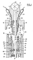
- the surface installations essentially comprise a block of valves 10 which is fixed in sealed manner by means of the seal 18, to the well head 20 by means of a fixing assembly 13.
- the well head 20 is adapted to receive a suspension device 21 intended to anchor the upper end of the casing 30.
- the suspension device 21 of the casing 30 is adapted to receive a suspension device 22 intended to anchor the upper end of the production column 40.
- the seal between the wellhead 20 and the suspension device 21 on the one hand, and between the suspension devices 21 and 22 on the other hand, is respectively ensured by the seals 23 and 24.
- the valve block 10 is equipped with valves 11 (a single valve 11 shown) making it possible to control the flow rate of the well through the main conduit 14.
- the lower part of the valve block 10 has a bore 12 arranged in the main conduit 14 and in which the upper end of a cylindrical connector 15 provided with O-rings 16 is sealingly fixed.
- the lower end of the connector 15, also provided with O-rings 17, is adapted to be fitted in a sealed manner in a bore 25 arranged in the suspension device 22 of the production column 40.
- the inductive coupling connector comprises at least two coils 1A and 5A, the winding axes of which coincide with the axis zz ′ of the well head 20, and which are integrated into the hydraulic connection formed between the block of valves 10 and the suspension device 22 of the production column 40, one of the coils being integral with the valve block 10 while the other of said coils is integral with the suspension device 22.
- the inductive coupling connector comprises on the one hand two electrical coils 1A and 1B wound around a first sleeve 1 secured to the connector 15, and on the other hand, two electrical coils 5A and 5B wound inside a second sleeve 5, removably attached, to the upper part of the suspension device 22.
- the sleeve 1 When the valve block 10 is installed on the well head 20, the sleeve 1 is housed in the sleeve 5 so that the coils 1A and 5A on the one hand, and the coils 1B and 5B on the other part respectively are placed concentrically facing each other, while allowing a clearance of at least 2 mm between them.
- each of the coils is housed in a groove coated, at least partially, with a highly ferromagnetic material such as ferrite.
- a waterproof material which resists pressure, temperature and corrosion, such as an elastomer or a silicone-based resin.
- the outputs of the coils 1A and 1B are respectively connected to conventional sealed bushings 2A and 2B, which are themselves connected by conductors 3A and 3B to sealed housings 4A and 4B located outside the valve block 10, each of boxes 4A and 4B being adapted to receive an electronic circuit which will be described below with reference to FIG. 3.
- the outputs of the coils 5A and 5B are connected to sealed boxes 6A and 6B housed in the suspension device 22 of the production column, each of the boxes being adapted to receive a second electronic circuit.
- the boxes 6A and 6B are connected to watertight bushings 7A and 7B which lead to the conductors 8A and 8B located in the annular space between the casing 30 and the production column 40.
- the conductors 8A and 8B are connected to the sensors (not shown) placed in the well.
- the inductive coupling connector according to the arrangement described above has the particular advantage of eliminating, during the positioning of the valve block 10, the positioning of the valve block 10 relative to the well head 20. It presents therefore as an electrical connection with centered quick coupling and fully integrated into the hydraulic connection that forms the connection between the wellhead 20 and the valve block 10. In addition, the maintenance of such a connector is facilitated by the fact that the coils 5A and 5B secured to the well head, are fixed to removable elements of the well head.
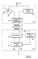
- FIG. 3 is a diagram of the electronic circuit associated with the connector with inductive coupling and intended to ensure the electrical connection between two sensors placed at the bottom of the well (not shown) and the surface control equipment (not shown); the two sensors can for example be used to measure pressure and temperature. In this case, the two sensors are supplied by the same cable and the selection of the signal returned to the surface is made by the polarity of the supply. In order to simplify the description, only the circuit associated with the coils 1A and 5A will be described.
- a first circuit which can in particular be housed in the housing 4A as mentioned above, is supplied by a current source 50.
- the supply current once rectified by the bridge 51, supplies a converter 52 responsible for transforming direct current into alternating current; the frequency of the latter is controlled by a polarity detector 53 also supplied by the current source 50.
- the output of the converter 52 directly supplies the coil 1A.
- a second circuit housed in the housing 6A comprises a converter 55 supplied by the coil 5A and responsible for transforming the alternating current into direct current.
- a polarity selector 56 controlled by a frequency detector 57 selects the polarity of the direct current delivered on the cable 8A so as to select the signals coming from one or the other of the sensors placed in the well.
- the voltage pulses generated by the sensors modulate the voltage amplitude at the terminals of the coil 5A through the converter 55 by synchronous impedance modulation.
- the converter 52 functions as a synchronous detector; it modulates the supply voltage with the voltage pulses after filtering the supply frequency.
- Such a circuit has the advantage that it requires only a single connector with inductive coupling for the telemetry of the two sensors; thus, a second circuit associated with the coils 1B and 5B could for example serve as a backup circuit in the event of failure of the first.
- the connector with inductive coupling comprises two coils having a substantially identical diameter and which overlap when the valve block 10 is installed on the well head 20.
Landscapes
- Engineering & Computer Science (AREA)
- Life Sciences & Earth Sciences (AREA)
- Geology (AREA)
- Mining & Mineral Resources (AREA)
- Physics & Mathematics (AREA)
- General Life Sciences & Earth Sciences (AREA)
- Geochemistry & Mineralogy (AREA)
- Environmental & Geological Engineering (AREA)
- Fluid Mechanics (AREA)
- Power Engineering (AREA)
- Remote Sensing (AREA)
- Geophysics (AREA)
- Electromagnetism (AREA)
- Magnetic Resonance Imaging Apparatus (AREA)
- Control Of Motors That Do Not Use Commutators (AREA)
- Earth Drilling (AREA)
- Details Of Connecting Devices For Male And Female Coupling (AREA)
- Quick-Acting Or Multi-Walled Pipe Joints (AREA)
- Magnetically Actuated Valves (AREA)
- Geophysics And Detection Of Objects (AREA)
Applications Claiming Priority (2)
| Application Number | Priority Date | Filing Date | Title |
|---|---|---|---|
| FR8816353A FR2640415B1 (fr) | 1988-12-13 | 1988-12-13 | Connecteur a accouplement inductif destine a equiper les installations de surface d'un puits |
| FR8816353 | 1988-12-13 |
Publications (2)
| Publication Number | Publication Date |
|---|---|
| EP0374016A2 true EP0374016A2 (de) | 1990-06-20 |
| EP0374016A3 EP0374016A3 (de) | 1991-05-29 |
Family
ID=9372858
Family Applications (1)
| Application Number | Title | Priority Date | Filing Date |
|---|---|---|---|
| EP19890403393 Withdrawn EP0374016A3 (de) | 1988-12-13 | 1989-12-07 | Induktiver Kopplungsverbinder zur Ausrüstung von Übertagebohrlochanlagen |
Country Status (4)
| Country | Link |
|---|---|
| US (1) | US5052941A (de) |
| EP (1) | EP0374016A3 (de) |
| FR (1) | FR2640415B1 (de) |
| NO (1) | NO177474C (de) |
Cited By (5)
| Publication number | Priority date | Publication date | Assignee | Title |
|---|---|---|---|---|
| EP0499547A1 (de) * | 1991-02-14 | 1992-08-19 | Elf Aquitaine Production | Unterwasser-Bohrlochkopf |
| EP0678880A1 (de) * | 1994-04-22 | 1995-10-25 | Panex Corporation | Induktiver Verbinder für Bohrlochwerkzeuge |
| WO1996032763A3 (en) * | 1995-04-12 | 1996-11-14 | Itt Ind Ltd | Electrical connector |
| EP0750323A4 (de) * | 1994-03-11 | 1997-06-04 | Yaskawa Denki Seisakusho Kk | Kontaktlose übertragungsanordnung und trägerstruktur zu deren anwendung |
| WO2000038202A1 (en) * | 1998-12-22 | 2000-06-29 | Raytheon Company | Apparatus and method for transferring energy across a connectorless interface |
Families Citing this family (105)
| Publication number | Priority date | Publication date | Assignee | Title |
|---|---|---|---|---|
| US5148864A (en) * | 1991-06-17 | 1992-09-22 | Camco International Inc. | High pressure electrical cable packoff and method of making |
| US5577925A (en) * | 1992-10-21 | 1996-11-26 | Halliburton Company | Concentric wet connector system |
| DE4300074C1 (de) * | 1993-01-05 | 1994-05-05 | Hans Kuehn | Vorrichtung zur Signal- und Datenübertragung für die Steuerung und Überwachung von Unterwasser-Ramm-, Trenn- oder dergleichen Arbeitsgeräten |
| DE4300073C2 (de) * | 1993-01-05 | 1994-10-27 | Hans Kuehn | Selbständige tauchfähige Antriebseinheit für unter Wasser einsetzbare Ramm- und Arbeitsgeräte |
| DE4300075C1 (de) * | 1993-01-05 | 1994-03-17 | Hans Kuehn | Anlage zur Übertragung von Antriebsenergie auf unter Wasser einsetzbare Ramm-, Trenn- oder dergleichen Arbeitsgeräte |
| US5389003A (en) * | 1993-09-13 | 1995-02-14 | Scientific Drilling International | Wireline wet connection |
| US5492017A (en) * | 1994-02-14 | 1996-02-20 | Abb Vetco Gray Inc. | Inductive pressure transducer |
| MY114154A (en) * | 1994-02-18 | 2002-08-30 | Shell Int Research | Wellbore system with retreivable valve body |
| US5820416A (en) * | 1996-01-04 | 1998-10-13 | Carmichael; Alan L. | Multiple contact wet connector |
| GB0016572D0 (en) * | 2000-07-05 | 2000-08-23 | Tronic Ltd | Connector |
| WO2002006716A1 (en) | 2000-07-19 | 2002-01-24 | Novatek Engineering Inc. | Data transmission system for a string of downhole components |
| US7040003B2 (en) * | 2000-07-19 | 2006-05-09 | Intelliserv, Inc. | Inductive coupler for downhole components and method for making same |
| US6439325B1 (en) | 2000-07-19 | 2002-08-27 | Baker Hughes Incorporated | Drilling apparatus with motor-driven pump steering control |
| US7098767B2 (en) * | 2000-07-19 | 2006-08-29 | Intelliserv, Inc. | Element for use in an inductive coupler for downhole drilling components |
| US6992554B2 (en) * | 2000-07-19 | 2006-01-31 | Intelliserv, Inc. | Data transmission element for downhole drilling components |
| US6670880B1 (en) | 2000-07-19 | 2003-12-30 | Novatek Engineering, Inc. | Downhole data transmission system |
| US6888473B1 (en) | 2000-07-20 | 2005-05-03 | Intelliserv, Inc. | Repeatable reference for positioning sensors and transducers in drill pipe |
| US6511335B1 (en) | 2000-09-07 | 2003-01-28 | Schlumberger Technology Corporation | Multi-contact, wet-mateable, electrical connector |
| US6768700B2 (en) | 2001-02-22 | 2004-07-27 | Schlumberger Technology Corporation | Method and apparatus for communications in a wellbore |
| US6866306B2 (en) | 2001-03-23 | 2005-03-15 | Schlumberger Technology Corporation | Low-loss inductive couplers for use in wired pipe strings |
| US6641434B2 (en) | 2001-06-14 | 2003-11-04 | Schlumberger Technology Corporation | Wired pipe joint with current-loop inductive couplers |
| GB2376487B (en) * | 2001-06-15 | 2004-03-31 | Schlumberger Holdings | Power system for a well |
| GB0115524D0 (en) * | 2001-06-26 | 2001-08-15 | Xl Technology Ltd | Conducting system |
| US6565119B2 (en) | 2001-07-11 | 2003-05-20 | Trw Inc. | Vehicle occupant safety apparatus with restraint communication bus and transformer connections |
| US6386895B1 (en) * | 2001-08-30 | 2002-05-14 | Richard B. Rehrig | Power cable adapter |
| US6609921B1 (en) * | 2001-08-30 | 2003-08-26 | Richard B. Rehrig | Power cable adapter |
| NO315068B1 (no) * | 2001-11-12 | 2003-06-30 | Abb Research Ltd | En innretning for elektrisk kobling |
| US7362235B1 (en) | 2002-05-15 | 2008-04-22 | Sandria Corporation | Impedance-matched drilling telemetry system |
| US7105098B1 (en) | 2002-06-06 | 2006-09-12 | Sandia Corporation | Method to control artifacts of microstructural fabrication |
| US6799632B2 (en) * | 2002-08-05 | 2004-10-05 | Intelliserv, Inc. | Expandable metal liner for downhole components |
| US7243717B2 (en) * | 2002-08-05 | 2007-07-17 | Intelliserv, Inc. | Apparatus in a drill string |
| US6763882B2 (en) | 2002-11-07 | 2004-07-20 | Seaboard International, Inc. | Insulated casing and tubing hangers |
| US7224288B2 (en) * | 2003-07-02 | 2007-05-29 | Intelliserv, Inc. | Link module for a downhole drilling network |
| US6982384B2 (en) * | 2003-09-25 | 2006-01-03 | Intelliserv, Inc. | Load-resistant coaxial transmission line |
| US7098802B2 (en) * | 2002-12-10 | 2006-08-29 | Intelliserv, Inc. | Signal connection for a downhole tool string |
| US6830467B2 (en) * | 2003-01-31 | 2004-12-14 | Intelliserv, Inc. | Electrical transmission line diametrical retainer |
| US6844498B2 (en) * | 2003-01-31 | 2005-01-18 | Novatek Engineering Inc. | Data transmission system for a downhole component |
| US7852232B2 (en) * | 2003-02-04 | 2010-12-14 | Intelliserv, Inc. | Downhole tool adapted for telemetry |
| US7096961B2 (en) * | 2003-04-29 | 2006-08-29 | Schlumberger Technology Corporation | Method and apparatus for performing diagnostics in a wellbore operation |
| US6929493B2 (en) * | 2003-05-06 | 2005-08-16 | Intelliserv, Inc. | Electrical contact for downhole drilling networks |
| US6913093B2 (en) * | 2003-05-06 | 2005-07-05 | Intelliserv, Inc. | Loaded transducer for downhole drilling components |
| US20050001738A1 (en) * | 2003-07-02 | 2005-01-06 | Hall David R. | Transmission element for downhole drilling components |
| US7053788B2 (en) * | 2003-06-03 | 2006-05-30 | Intelliserv, Inc. | Transducer for downhole drilling components |
| US6981546B2 (en) * | 2003-06-09 | 2006-01-03 | Intelliserv, Inc. | Electrical transmission line diametrical retention mechanism |
| US20050001736A1 (en) * | 2003-07-02 | 2005-01-06 | Hall David R. | Clamp to retain an electrical transmission line in a passageway |
| US6950034B2 (en) * | 2003-08-29 | 2005-09-27 | Schlumberger Technology Corporation | Method and apparatus for performing diagnostics on a downhole communication system |
| US7019665B2 (en) * | 2003-09-02 | 2006-03-28 | Intelliserv, Inc. | Polished downhole transducer having improved signal coupling |
| US6991035B2 (en) * | 2003-09-02 | 2006-01-31 | Intelliserv, Inc. | Drilling jar for use in a downhole network |
| US20050074998A1 (en) * | 2003-10-02 | 2005-04-07 | Hall David R. | Tool Joints Adapted for Electrical Transmission |
| US7040415B2 (en) * | 2003-10-22 | 2006-05-09 | Schlumberger Technology Corporation | Downhole telemetry system and method |
| US20050093296A1 (en) * | 2003-10-31 | 2005-05-05 | Hall David R. | An Upset Downhole Component |
| US7017667B2 (en) * | 2003-10-31 | 2006-03-28 | Intelliserv, Inc. | Drill string transmission line |
| US6968611B2 (en) * | 2003-11-05 | 2005-11-29 | Intelliserv, Inc. | Internal coaxial cable electrical connector for use in downhole tools |
| US6945802B2 (en) * | 2003-11-28 | 2005-09-20 | Intelliserv, Inc. | Seal for coaxial cable in downhole tools |
| US20050115717A1 (en) * | 2003-11-29 | 2005-06-02 | Hall David R. | Improved Downhole Tool Liner |
| US7291303B2 (en) * | 2003-12-31 | 2007-11-06 | Intelliserv, Inc. | Method for bonding a transmission line to a downhole tool |
| US7069999B2 (en) * | 2004-02-10 | 2006-07-04 | Intelliserv, Inc. | Apparatus and method for routing a transmission line through a downhole tool |
| US20050212530A1 (en) * | 2004-03-24 | 2005-09-29 | Hall David R | Method and Apparatus for Testing Electromagnetic Connectivity in a Drill String |
| US7168510B2 (en) * | 2004-10-27 | 2007-01-30 | Schlumberger Technology Corporation | Electrical transmission apparatus through rotating tubular members |
| US7413021B2 (en) * | 2005-03-31 | 2008-08-19 | Schlumberger Technology Corporation | Method and conduit for transmitting signals |
| DE102005022367B4 (de) | 2005-05-10 | 2021-05-20 | Sew-Eurodrive Gmbh & Co Kg | Berührungslos versorgter Verbraucher und System |
| US8286713B2 (en) * | 2005-05-18 | 2012-10-16 | Argus Subsea, Inc. | Oil and gas well completion system and method of installation |
| US7543659B2 (en) * | 2005-06-15 | 2009-06-09 | Schlumberger Technology Corporation | Modular connector and method |
| US7913774B2 (en) * | 2005-06-15 | 2011-03-29 | Schlumberger Technology Corporation | Modular connector and method |
| US7913773B2 (en) * | 2005-08-04 | 2011-03-29 | Schlumberger Technology Corporation | Bidirectional drill string telemetry for measuring and drilling control |
| US20070030167A1 (en) * | 2005-08-04 | 2007-02-08 | Qiming Li | Surface communication apparatus and method for use with drill string telemetry |
| US7777644B2 (en) * | 2005-12-12 | 2010-08-17 | InatelliServ, LLC | Method and conduit for transmitting signals |
| NO324407B1 (no) * | 2006-01-24 | 2007-10-08 | Ifokus Engineering As | Anordning ved koplingsdor for anvendelse under vann |
| US7793718B2 (en) * | 2006-03-30 | 2010-09-14 | Schlumberger Technology Corporation | Communicating electrical energy with an electrical device in a well |
| US8056619B2 (en) * | 2006-03-30 | 2011-11-15 | Schlumberger Technology Corporation | Aligning inductive couplers in a well |
| US7336199B2 (en) * | 2006-04-28 | 2008-02-26 | Halliburton Energy Services, Inc | Inductive coupling system |
| US7748444B2 (en) * | 2007-03-02 | 2010-07-06 | Schlumberger Technology Corporation | Method and apparatus for connecting, installing, and retrieving a coiled tubing-conveyed electrical submersible pump |
| US7931079B2 (en) * | 2007-08-17 | 2011-04-26 | Schlumberger Technology Corporation | Tubing hanger and method of compensating pressure differential between a tubing hanger and an external well volume |
| US8102230B2 (en) * | 2007-10-12 | 2012-01-24 | Eriksen Electric Power Systems As | Inductive coupler connector |
| US8322440B2 (en) * | 2008-03-06 | 2012-12-04 | Vetco Gray Inc. | Integrated electrical connector for use in a wellhead tree |
| US7967066B2 (en) * | 2008-05-09 | 2011-06-28 | Fmc Technologies, Inc. | Method and apparatus for Christmas tree condition monitoring |
| US7845404B2 (en) * | 2008-09-04 | 2010-12-07 | Fmc Technologies, Inc. | Optical sensing system for wellhead equipment |
| US20100243242A1 (en) * | 2009-03-27 | 2010-09-30 | Boney Curtis L | Method for completing tight oil and gas reservoirs |
| US8857510B2 (en) * | 2009-04-03 | 2014-10-14 | Schlumberger Technology Corporation | System and method for determining movement of a drilling component in a wellbore |
| US8552876B2 (en) * | 2009-05-22 | 2013-10-08 | The Patent Store Llc | Intelligent wire connectors |
| AT508272B1 (de) * | 2009-06-08 | 2011-01-15 | Advanced Drilling Solutions Gmbh | Vorrichtung zum verbinden von elektrischen leitungen |
| US9063250B2 (en) | 2009-08-18 | 2015-06-23 | Schlumberger Technology Corporation | Interference testing while drilling |
| US8680704B1 (en) | 2009-09-18 | 2014-03-25 | Taylor Valve Technology, Inc. | Wellhead pressure reduction and electrical power generation |
| US8851175B2 (en) | 2009-10-20 | 2014-10-07 | Schlumberger Technology Corporation | Instrumented disconnecting tubular joint |
| US8192213B2 (en) * | 2009-10-23 | 2012-06-05 | Intelliserv, Llc | Electrical conduction across interconnected tubulars |
| US8362915B2 (en) | 2009-10-30 | 2013-01-29 | Intelliserv, Llc | System and method for determining stretch or compression of a drill string |
| US8905159B2 (en) * | 2009-12-15 | 2014-12-09 | Schlumberger Technology Corporation | Eccentric steering device and methods of directional drilling |
| US8198752B2 (en) * | 2010-05-12 | 2012-06-12 | General Electric Company | Electrical coupling apparatus and method |
| US8441153B2 (en) * | 2010-06-22 | 2013-05-14 | General Electric Company | Contactless power transfer system |
| US8988178B2 (en) | 2010-07-05 | 2015-03-24 | Schlumberger Technology Corporation | Downhole inductive coupler assemblies |
| EP2415961A1 (de) * | 2010-08-03 | 2012-02-08 | Vetco Gray Controls Limited | Stromversorgung für Unterwasservorrichtungen |
| US8727035B2 (en) | 2010-08-05 | 2014-05-20 | Schlumberger Technology Corporation | System and method for managing temperature in a wellbore |
| EP2642609A1 (de) * | 2012-03-23 | 2013-09-25 | Erbe Elektromedizin GmbH | Steckverbinderteil für ein medizinisches Gerät oder Instrument |
| GB2504301B (en) | 2012-07-24 | 2019-02-20 | Accessesp Uk Ltd | Downhole electrical wet connector |
| US20150061885A1 (en) * | 2013-08-28 | 2015-03-05 | Baker Hughes Incorporated | Wired pipe surface sub |
| US9915145B2 (en) | 2014-03-06 | 2018-03-13 | Halliburton Energy Services, Inc. | Downhole power and data transfer using resonators |
| US9466916B2 (en) * | 2014-05-21 | 2016-10-11 | Schlumberger Technology Corporation | Multi-contact connector assembly |
| CN109964002A (zh) | 2016-12-20 | 2019-07-02 | 哈利伯顿能源服务公司 | 用于井下电感耦合的方法和系统 |
| US10774608B2 (en) * | 2017-02-03 | 2020-09-15 | Onesubsea Ip Uk Limited | Subsea system and methodology utilizing production receptacle structure |
| US11605986B2 (en) | 2017-12-19 | 2023-03-14 | Colder Products Company | Systems and methods for wireless power and data transfer for connectors |
| EP3511516A1 (de) * | 2018-01-16 | 2019-07-17 | Siemens Aktiengesellschaft | Unterwassergehäuseanordnung |
| WO2020081911A1 (en) * | 2018-10-18 | 2020-04-23 | Dril-Quip, Inc. | Non-orientating tubing hanger and tree |
| US11359441B2 (en) * | 2020-04-20 | 2022-06-14 | Vertechs Nova Technology Co., Ltd. | Wet connector for trident rigless electrical submersible pump (ESP) technology |
| US11296466B2 (en) * | 2020-07-30 | 2022-04-05 | The Esab Group Inc. | Coradial connector |
| US11346174B1 (en) * | 2021-07-27 | 2022-05-31 | Benton Frederick Baugh | Method for integrating choke lines, kill lines, and hydraulic control lines into a mandrel |
Family Cites Families (10)
| Publication number | Priority date | Publication date | Assignee | Title |
|---|---|---|---|---|
| US2379800A (en) * | 1941-09-11 | 1945-07-03 | Texas Co | Signal transmission system |
| US3079549A (en) * | 1957-07-05 | 1963-02-26 | Philip W Martin | Means and techniques for logging well bores |
| US3090031A (en) * | 1959-09-29 | 1963-05-14 | Texaco Inc | Signal transmission system |
| GB1571677A (en) * | 1978-04-07 | 1980-07-16 | Shell Int Research | Pipe section for use in a borehole |
| GB2058474B (en) * | 1979-08-31 | 1983-11-09 | Westinghouse Electric Corp | Inductive coupler |
| US4605268A (en) * | 1982-11-08 | 1986-08-12 | Nl Industries, Inc. | Transformer cable connector |
| DE3402386A1 (de) * | 1984-01-25 | 1985-08-01 | Licentia Patent-Verwaltungs-Gmbh, 6000 Frankfurt | Induktive energie- und datenuebertragung |
| GB8407473D0 (en) * | 1984-03-22 | 1984-05-02 | Framo Dev Ltd | Electric power transmission to submerged installations |
| US4901069A (en) * | 1987-07-16 | 1990-02-13 | Schlumberger Technology Corporation | Apparatus for electromagnetically coupling power and data signals between a first unit and a second unit and in particular between well bore apparatus and the surface |
| US4852648A (en) * | 1987-12-04 | 1989-08-01 | Ava International Corporation | Well installation in which electrical current is supplied for a source at the wellhead to an electrically responsive device located a substantial distance below the wellhead |
-
1988
- 1988-12-13 FR FR8816353A patent/FR2640415B1/fr not_active Expired - Lifetime
-
1989
- 1989-12-07 EP EP19890403393 patent/EP0374016A3/de not_active Withdrawn
- 1989-12-12 NO NO894994A patent/NO177474C/no not_active IP Right Cessation
-
1990
- 1990-12-20 US US07/631,748 patent/US5052941A/en not_active Expired - Lifetime
Cited By (9)
| Publication number | Priority date | Publication date | Assignee | Title |
|---|---|---|---|---|
| EP0499547A1 (de) * | 1991-02-14 | 1992-08-19 | Elf Aquitaine Production | Unterwasser-Bohrlochkopf |
| FR2672935A1 (fr) * | 1991-02-14 | 1992-08-21 | Elf Aquitaine | Tete de puits sous-marine. |
| US5213162A (en) * | 1991-02-14 | 1993-05-25 | Societe Nationale Elf Aquitaine (Production) | Submarine wellhead |
| EP0750323A4 (de) * | 1994-03-11 | 1997-06-04 | Yaskawa Denki Seisakusho Kk | Kontaktlose übertragungsanordnung und trägerstruktur zu deren anwendung |
| US5747894A (en) * | 1994-03-11 | 1998-05-05 | Kabushiki Kaisha Yaskawa Denki | Factory automation connector and work pallet |
| EP0678880A1 (de) * | 1994-04-22 | 1995-10-25 | Panex Corporation | Induktiver Verbinder für Bohrlochwerkzeuge |
| WO1996032763A3 (en) * | 1995-04-12 | 1996-11-14 | Itt Ind Ltd | Electrical connector |
| WO2000038202A1 (en) * | 1998-12-22 | 2000-06-29 | Raytheon Company | Apparatus and method for transferring energy across a connectorless interface |
| US6268785B1 (en) | 1998-12-22 | 2001-07-31 | Raytheon Company | Apparatus and method for transferring energy across a connectorless interface |
Also Published As
| Publication number | Publication date |
|---|---|
| FR2640415A1 (fr) | 1990-06-15 |
| NO177474C (no) | 1995-09-20 |
| NO177474B (no) | 1995-06-12 |
| NO894994L (no) | 1990-06-14 |
| FR2640415B1 (fr) | 1994-02-25 |
| EP0374016A3 (de) | 1991-05-29 |
| NO894994D0 (no) | 1989-12-12 |
| US5052941A (en) | 1991-10-01 |
Similar Documents
| Publication | Publication Date | Title |
|---|---|---|
| EP0374016A2 (de) | Induktiver Kopplungsverbinder zur Ausrüstung von Übertagebohrlochanlagen | |
| US6371693B1 (en) | Making subsea pipelines ready for electrical heating | |
| US7955105B2 (en) | Connector arrangement with penetrator in a submersible electrical assembly | |
| JP6058670B2 (ja) | 電気−光イーサネット伝送システム用の海底電気−光コネクタ・ユニット | |
| US5183966A (en) | Termination assembly with improved waterblock | |
| EP0816632A1 (de) | Vorrichtung und Verfahren zur Übertragung von Nachrichten mittels elektromagnetischer Wellen | |
| FR2697119A1 (fr) | Dispositif émetteur à double raccord isolant, destiné à l'emploi dans un forage. | |
| RU2070679C1 (ru) | Тюбинговая муфта | |
| EP2283202A2 (de) | Kabelsteckersystem für ein verdrahtetes bohrrohr | |
| EP3104480A1 (de) | Unterseeisches datenübertragungskabel | |
| US10097060B2 (en) | Systems and methods for preventing electrical faults associated with motor leads | |
| EP2497174A2 (de) | System zur stromleitung durch eine wand | |
| GB9826630D0 (en) | Electrical connector system | |
| CN106685630A (zh) | 井下双向通讯装置 | |
| CA1169764A (en) | Concentric electric connector for subsea well apparatus | |
| EP0454717A1 (de) | Elektrisch leitender untersee-kopplungseinsatz. | |
| FR2522721A1 (fr) | Dispositif de connexion electrique pour tete de puits sous-marine | |
| US6179585B1 (en) | Modular plug connector for use with a submergible pumping system | |
| CN112483010B (zh) | 一种井下工具 | |
| US11814929B2 (en) | Subsea hydrocarbon flowline system and related method and use | |
| EP2390698A1 (de) | Abgedichtete optoelektronische Isolationsverbindungsvorrichtung und abgedichtete Kabine | |
| US20260071511A1 (en) | Harness | |
| US7189312B2 (en) | Under water cable system having an earthing electrode | |
| CN119013456A (zh) | 潜水式高电压电连接器 | |
| CA3080213C (en) | Rotating joint and coiled tubing unit |
Legal Events
| Date | Code | Title | Description |
|---|---|---|---|
| PUAI | Public reference made under article 153(3) epc to a published international application that has entered the european phase |
Free format text: ORIGINAL CODE: 0009012 |
|
| AK | Designated contracting states |
Kind code of ref document: A2 Designated state(s): DE GB IT NL |
|
| PUAL | Search report despatched |
Free format text: ORIGINAL CODE: 0009013 |
|
| AK | Designated contracting states |
Kind code of ref document: A3 Designated state(s): DE GB IT NL |
|
| 17P | Request for examination filed |
Effective date: 19911127 |
|
| 17Q | First examination report despatched |
Effective date: 19921119 |
|
| STAA | Information on the status of an ep patent application or granted ep patent |
Free format text: STATUS: THE APPLICATION IS DEEMED TO BE WITHDRAWN |
|
| 18D | Application deemed to be withdrawn |
Effective date: 19950523 |