EP0374056A2 - Alpinskischuh der Bauart mit rückwärtigem Einstieg - Google Patents
Alpinskischuh der Bauart mit rückwärtigem Einstieg Download PDFInfo
- Publication number
- EP0374056A2 EP0374056A2 EP89420423A EP89420423A EP0374056A2 EP 0374056 A2 EP0374056 A2 EP 0374056A2 EP 89420423 A EP89420423 A EP 89420423A EP 89420423 A EP89420423 A EP 89420423A EP 0374056 A2 EP0374056 A2 EP 0374056A2
- Authority
- EP
- European Patent Office
- Prior art keywords
- support
- axis
- shell
- ski boot
- stirrup
- Prior art date
- Legal status (The legal status is an assumption and is not a legal conclusion. Google has not performed a legal analysis and makes no representation as to the accuracy of the status listed.)
- Granted
Links
Images




Classifications
-
- A—HUMAN NECESSITIES
- A43—FOOTWEAR
- A43B—CHARACTERISTIC FEATURES OF FOOTWEAR; PARTS OF FOOTWEAR
- A43B5/00—Footwear for sporting purposes
- A43B5/04—Ski or like boots
- A43B5/0427—Ski or like boots characterised by type or construction details
- A43B5/0452—Adjustment of the forward inclination of the boot leg
-
- A—HUMAN NECESSITIES
- A43—FOOTWEAR
- A43B—CHARACTERISTIC FEATURES OF FOOTWEAR; PARTS OF FOOTWEAR
- A43B5/00—Footwear for sporting purposes
- A43B5/04—Ski or like boots
- A43B5/0427—Ski or like boots characterised by type or construction details
- A43B5/048—Rear-entry skiboots
Definitions
- the present invention relates to an alpine ski boot of the "rear entry" type, comprising a rigid shell bottom and a rod articulated on this shell bottom, about a horizontal and transverse axis.
- the opening axis that is to say the one around which the upper tilts, must be situated relatively close to the ground, for obvious reasons of kinematics, to make it as easy as possible for the foot to enter the shoe when putting on.
- this axis also serves as the bending axis of the rod, during skiing, the correspondence between this axis and the articulation of the skier's ankle is not ensured.
- two alpine ski boots comprising a rod articulated in two parts, that is to say constituted by a front cuff and a rear cover, have two axes of articulation, namely one for the front cuff, located in the ankle area, and the other for the back cover, located in the lower heel area.
- a shoe is described, for example, in patent EP-A-0 119 566.
- the two axes work simultaneously and constitute points of articulation of the front cuff and the rear cover. which then move in the same way as the two sides of a deformable parallelogram.
- such a displacement results in a translational movement of the front cuff and the rear cover relative to the leg, hence annoying friction on the lower leg.
- the present invention aims to remedy the disadvantages of alpine ski boots known to date and in particular those of boots with two axes of articulation of the upper thanks to a particularly simple and effective design of the whole of the device ensuring the articulated connection between the upper of the boot and the bottom of the hull.
- this alpine ski boot of the rear entry type comprising a shell bottom and an at least partly rod, articulated on the shell bottom
- a support itself articulated on the shell bottom around a horizontal and transverse articulation axis
- the rod being articulated on the support around an axis distinct from the previous one
- the shoe comprises locking means to immobilize the support and consequently the axis of articulation of the rod on the support in a first high position for skiing and to release this support, during heaving, in order to allow the support to pivot relative to the bottom shell, around its axis, towards a second low position causing a rearward displacement, and possibly downward, of the axis of articulation of the rod on the support.
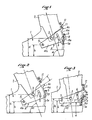
- the alpine ski boot according to the invention which is shown in Figures 1 to 3, comprises a rigid shell bottom 1 and an articulated rod 2 which, in this non-limiting embodiment, consists of a single piece.
- the rod 2 is articulated, at its lower part, around a horizontal and transverse axis 3, on a support 4 which is itself articulated, at its front part, on the bottom of the shell 1, around a horizontal and transverse axis 5 located in front of the axis 3.
- the skiing practice position as shown in FIGS.
- the articulation axis 3 of the rod 2 on the support 4 is located at a height H, relative to the underside of the sole of the shoe, which is greater than the constant height h of the hinge pin 5 of the support 4 on the bottom of the shell 1 relative to this same underside of the sole.
- the support 4 is constituted by a stirrup surrounding the rear of the bottom of the shell 1 and more particularly this stirrup 4 comprises a rear core 4a which is located just above the rear wall 1a of the bottom of the hull. 1, partially covering the latter, and two lateral branches 4b which extend forward and which are inclined up and down and from back to front in the skiing practice position shown in FIGS. 1 and 2.
- Each of the lateral branches 4b of the stirrup 4 is connected, in its anterior end portion, to the bottom of the shell 1, by means of a stud materializing the transverse articulation axis 5, the two studs 5 being coaxial.
- Each lateral branch 4b is also linked to a lateral lower part of the rod 2, by means of a stud materializing the axis hinge 3 of the rod.
- the stirrup 4 constituting the support of the rod 2 can pivot by a certain angle around the articulation axis 5, between a high ski practice position shown in FIGS. 1 and 2 and a low boot position. heaving shown in FIG. 3.
- This angular movement is limited in both directions by a stop device and this device can comprise, for example, a lug 6 secured to the bottom of the shell 1 and which is engaged in an arched light 7 which is formed in the lateral branch 4b of the stirrup 4 while being centered on the articulation axis 5.
- the reverse arrangement could also be adopted, that is to say by providing the lug 6 on the lateral branch 4b of the stirrup 4, this lug 6 then engaging in a groove or an arcuate groove formed in the side wall of the bottom of the shell 1.
- a locking device is provided to immobilize the stirrup 4 in its high position for skiing.
- This locking device may comprise, for example, a pawl 8 articulated on the core 4a of the stirrup 4, outside of the latter, around a horizontal and transverse axis 9, this pawl, in the form of L, comprising a lower branch 8a, which crosses the core 4a of the stirrup 4 and which can be placed, in the high skiing position, just above the upper edge of the rear wall 1a of the bottom of the hull 1, so as to be in abutment against this edge. Therefore the pawl 8 normally opposes any pivoting movement of the stirrup 4 downwards.
- the rod 2 In the normal skiing position, the rod 2 has a certain forward inclination relative to the horizontal plane, this inclination corresponding to the angle represented in FIG. 1.
- This inclination or advance of the rod 2 can be adjusted at will by means of a device for adjusting the advance of the rod 2 interposed between it ci and the posterior core 4a of the stirrup 4.
- This device can be constituted, in this non-limiting embodiment, by a screw 11 which is screwed into a threaded hole provided in a tab 12 extending towards the rear from the rear wall of the rod 2 and the head of which is accessible from the top.
- the lower end of the screw 11 is supported on a spout 4c projecting outwards, which is provided at the upper end of the core 4a of the stirrup 4.
- the stirrup 4 is kept locked in the high position, by means of the pawl 8 bearing, by its lower branch 8a, on the upper edge of the rear wall 1a of the bottom of the shell 1.
- the rod 2 can bend more or less forward, during skiing, as shown in FIG. 2 where it can be seen that the rod 2 is inclined towards the front by an angle a1 greater than the angle a corresponding to the normal position represented in FIG. 1 and in which the rod 2 is in rear support on the stirrup 4, by means of the screw 11.
- the stirrup 4 carries a lock 13 of the pusher type which is urged elastically in the direction of the rear wall 1a of the bottom of the shell 1 by a non-spring shown, in order to be able to engage in a hollow formed in this wall 1a.
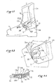
- the plunger 13 can be slidably mounted in the rear core 4a of the stirrup 4, as shown in FIG. 4, or in a lateral branch 4b of the stirrup 4.
- a device 10 for controlling the stiffness of the rod 2 in front bending is mounted between the rear wall of this rod 2 and the rear core 4a of the stirrup 4.
- FIG. 5 illustrates the application of the invention to an alpine ski boot, the upper 2 of which is made up of two parts and comprises a front cuff 2a and a rear cover 2b, these two parts being articulated together on the stirrup 4 around of the common axis 3.
- the alpine ski boot includes a stirrup 14 which is shaped in a different way since it does not surround the rear of the bottom of the shell 1 but it extends over the above the anterior part of it.
- the stirrup 14 comprises an anterior core 14a, extending above the inclined anterior and upper wall 1b of the bottom of the shell 1, and on each side of the bottom of the shell 1, an anterior lateral branch 14b and a posterior lateral branch 14c, these two lateral branches 14b, 14c forming an obtuse angle V open upwards and which is articulated, at the point of its top, on the shell bottom 1, around the axis 5.
- the rod 2 is articulated on each rear lateral branch 14c of the stirrup 14, around the axis 3, which is, here again, located above and behind the articulation axis 5 of the stirrup 14 on the bottom of the hull 1.
- the stirrup 14 is locked in the ski practice position by means of a locking device 15 which cooperates with the core 14a of the stirrup 14 and which is fixed to the inclined upper wall 1b of the bottom of the hull 1.
- the rear branch 14c is held in place by the locking device 15 , in the high position, as well as the hinge pin 3 of the rod 2 on the stirrup 14, and this rear branch 14c is lowered, together with the hinge pin 3, when the stirrup 14 is unlocked , in the shoe on / off position.
- the ski boot comprises a rod 2 made in two parts, namely a front cuff 2a and a rear cover 2b and in this case only the rear cover 2b is articulated on the caliper 4, around the axis 3.
- the front cuff 2a is, for its part, articulated, at its lower part, directly on the bottom of the shell 1, around an independent fixed axis 16.
- the two axes 3.16 are coaxial and are located at the articulation of the ankle of the skier and it follows that the upper 2 of the shoe pivots relative to the bottom of the shell around of a single axis 3.16.
- the front cuff 2a remains in position on the bottom of the shell 1 when the rear cover 2b is lowered towards the rear , which makes it easier to put on and take off.
- Figures 9 and 10 show an alternative embodiment of the alpine ski boot illustrated in Figure 6 but in this case the rod 2 is again made in two parts namely a front cuff 2a and a cover rear 2b.
- the front cuff 2a is articulated on the bottom of the shell 1, around the axis 16, while the rear cover 2b is alone articulated on the stirrup 14 and more particularly on its rear lateral branch 14c, around the axis 3
- the two axes 3.16 are coaxial while in the boot-release position (FIG. 10), the axis 3 is lowered relative to the axis 16 which is fixed and the rear cover of 2b is tilted down and back.
- FIG. 11 illustrates the application of the invention to a ski boot in which the upper 2, produced in two parts comprises a front cuff 2a which is integral with the bottom of the shell 1, by means of a flexion zone 17, and a rear cover 2b which alone can tilt around the axis 5.
- the rear cover 2b is alone articulated on the stirrup 4 around the axis 3.
- the shoe comprises a rigid shell bottom 1 and an articulated rod 2 which is produced in two parts, namely a front cuff 2a and a rear cover 2b.
- the front cuff 2a is articulated, at its lower part, directly on the bottom of the shell 1, around a fixed transverse axis 16 located substantially at the ankle of the skier's foot.
- This articulation axis 16 is materialized by a stud 20 passing through holes drilled in the bottom of the shell 1 and the front cuff 2a, these holes possibly having different diameters.
- the stud 20 ends, at its two ends, with heads 20a and 20b forming rivets situated respectively inside the wall of the bottom of the shell 1, against this wall, and outside of the front cuff 2a, against the external face thereof.
- the rear cover 2b of the rod 2 is, for its part, articulated around a horizontal and transverse axis 3, on the support 4 which is itself articulated on the bottom of the shell 1, at its front and lower part, around d 'a horizontal and transverse axis 5 located lower than the axis 3.
- the support 4 has the shape of a stirrup surrounding the rear of the bottom of the shell 1 and which comprises two lateral wings 4b extending forwardly and tilted up and down and back and forth in the skiing position.
- This support 4 carries a locking device 13 which makes it possible to make the stirrup forming support 4 integral with the bottom of the shell 1, during skiing.
- This locking device 13 can be placed at any suitable location on the support and is preferably mounted at the rear as shown in FIG. 12.
- the articulation, around the transverse axis 3, between the rear cover 2b and each of the wings 4b of the stirrup 4 forming a support is produced by means of a boss cylindrical 21, of circular cross section, centered on the axis 3, and which is engaged in a circular opening 22, of the same radius.
- the cylindrical boss 21 forms an integral part of the wing 4b of the stirrup 4 forming a support and it projects outwards from this wing in order to engage in the 'circular opening 22 which is itself provided in a lower and anterior wing of the rear cover 2b which is located outside with respect to the stirrup 4.
- the pin 20 which materializes the hinge pin 16 of the front cuff 2a on the bottom of the shell 1, passes through a slot 23 which extends right through the thickened zone where the circular boss 21 formed by the wing 4b is formed.
- This light 23 can have any shape and in particular it can have a width substantially equal to the diameter of the stud 20 and extend in an arc 24 which is centered on the axis of articulation 5 of the stirrup forming support 4 on the bottom of the shell 1 and which passes through the axis 3, as can best be seen in FIG. 2.
- the stud 20 engaged through the light 23 constitutes a stop which limits, in cooperation with the posterior 23a and anterior 23b ends of the lumen 23, the amplitude of the angular tilting movement of the stirrup 4 forming a support around the axis 5.
- FIG. 15 represents a position of the rod 2 which is bent more forward than the rod shown in FIG. 12.
- the axis 3 of the circular boss 21, that is to say the axis of articulation of the rear cover 2b on the stirrup forming support 4 is found offset backwards with respect to the hinge pin 16 of the front cuff 2a on the b ace of hull 1, as can best be seen in FIGS. 17 and 18.
- the offset towards the rear of the rear cover 2b which results therefrom thus facilitates the operation of putting on and taking off.
- the lumen 23 is shown as opening into the front edge of the lateral wing 4b of the stirrup 4 forming a support and into that of the rear cover 2b. This makes it possible to obtain a greater amplitude of angular movement of the stirrup forming the support 4 downwards since the stud 20 can then come completely out of the light 23.
- FIG. 22 illustrates an alternative embodiment in which the circular boss 21 materializing the axis of articulation 3 of the rear cover 2b on the stirrup forming support 4, is provided on the internal face of the lateral wing of the rear cover 2b and extends inwardly for s tightly engage in a circular opening 22 of the same radius provided in the lateral wing 4b of the stirrup 4.
Landscapes
- Health & Medical Sciences (AREA)
- General Health & Medical Sciences (AREA)
- Physical Education & Sports Medicine (AREA)
- Footwear And Its Accessory, Manufacturing Method And Apparatuses (AREA)
Applications Claiming Priority (4)
| Application Number | Priority Date | Filing Date | Title |
|---|---|---|---|
| FR8816400A FR2640122B1 (fr) | 1988-12-13 | 1988-12-13 | Chaussure de ski alpin du type a entree arriere |
| FR8816400 | 1988-12-13 | ||
| FR8911991 | 1989-09-13 | ||
| FR8911991A FR2651647A2 (en) | 1989-09-13 | 1989-09-13 | Rear-entry alpine ski boot |
Publications (3)
| Publication Number | Publication Date |
|---|---|
| EP0374056A2 true EP0374056A2 (de) | 1990-06-20 |
| EP0374056A3 EP0374056A3 (en) | 1990-08-16 |
| EP0374056B1 EP0374056B1 (de) | 1994-06-01 |
Family
ID=26227046
Family Applications (1)
| Application Number | Title | Priority Date | Filing Date |
|---|---|---|---|
| EP89420423A Expired - Lifetime EP0374056B1 (de) | 1988-12-13 | 1989-11-03 | Alpinskischuh der Bauart mit rückwärtigem Einstieg |
Country Status (5)
| Country | Link |
|---|---|
| US (1) | US5031341A (de) |
| EP (1) | EP0374056B1 (de) |
| JP (1) | JPH02200206A (de) |
| AT (1) | ATE106200T1 (de) |
| DE (1) | DE68915716T2 (de) |
Cited By (3)
| Publication number | Priority date | Publication date | Assignee | Title |
|---|---|---|---|---|
| FR2672189A1 (fr) * | 1991-02-01 | 1992-08-07 | Salomon Sa | Chaussure de ski a capot arriere articule sur le bras de coque. |
| EP0514290A1 (de) * | 1991-05-14 | 1992-11-19 | Skis Rossignol S.A. | Schischuh mit Schale und Schaftmanschette |
| CH688639A5 (fr) * | 1993-07-14 | 1997-12-31 | Lange Int Sa | Chaussure de ski. |
Families Citing this family (31)
| Publication number | Priority date | Publication date | Assignee | Title |
|---|---|---|---|---|
| FR2656201B1 (fr) * | 1989-12-22 | 1994-10-07 | Salomon Sa | Chaussure de ski de piste. |
| FR2657504B1 (fr) * | 1990-01-26 | 1992-04-03 | Salomon Sa | Chaussure de ski alpin, a collier de serrage arriere articule. |
| FR2657503B1 (fr) * | 1990-01-26 | 1994-09-23 | Salomon Sa | Chaussure de ski a entree arriere. |
| CH682879A5 (fr) * | 1990-04-24 | 1993-12-15 | Lange Int Sa | Chaussure de ski. |
| FR2674106A1 (fr) * | 1991-03-21 | 1992-09-25 | Salomon Sa | Chaussure de ski alpin a etrier d'energie articule sur le capot arriere. |
| FR2674107A1 (fr) * | 1991-03-21 | 1992-09-25 | Salomon Sa | Chaussure de ski alpin a volet d'energie articule sur le bas de coque. |
| FR2678490B1 (fr) * | 1991-07-01 | 1993-09-24 | Salomon Sa | Chaussure de ski avec dispositif de blocage de tige. |
| FR2678489B1 (fr) * | 1991-07-01 | 1993-09-24 | Salomon Sa | Chaussure de ski munie d'un dispositif d'immobilisation en pivotement de la tige. |
| JPH05184402A (ja) * | 1991-07-05 | 1993-07-27 | Nordica Spa | スキーブーツ |
| FR2680642B1 (fr) * | 1991-09-04 | 1993-12-03 | Salomon Sa | Dispositif de reglage d'avancee pour chaussure de ski. |
| FR2702935B1 (fr) * | 1993-03-24 | 1995-06-09 | Salomon Sa | Chaussure pour sport de glisse. |
| CH688635A5 (fr) * | 1993-04-02 | 1997-12-31 | Lange Int Sa | Chaussure de ski. |
| US5437466B1 (en) * | 1993-07-19 | 1997-11-18 | K 2 Corp | In-line roller skate |
| US6168172B1 (en) | 1993-07-19 | 2001-01-02 | K-2 Corporation | In-line roller skate |
| US5906058A (en) * | 1993-07-19 | 1999-05-25 | K-2 Corporation | Snowboard boot having a rigid strut |
| US5431624A (en) * | 1994-03-23 | 1995-07-11 | Saxton; Loren | Therapeutic device for controlling orientation of a patient's foot with respect to the patients leg during a recovery period |
| US5957479A (en) * | 1995-03-02 | 1999-09-28 | Items International, Inc. | Snowboard binding assembly |
| US6109643A (en) * | 1995-03-02 | 2000-08-29 | Airwalk International Llc | Snowboard binding assembly |
| FR2740011B1 (fr) * | 1995-10-20 | 1997-12-12 | Salomon Sa | Chaussure a tige ajustable |
| FR2745475B1 (fr) * | 1996-03-04 | 1998-05-07 | Salomon Sa | Chaussure avec renfort de transmission des efforts |
| US6027136A (en) * | 1997-01-08 | 2000-02-22 | The Burton Corporation | System for preventing toe-edge travel of a hi-back |
| US5832635A (en) * | 1997-01-17 | 1998-11-10 | Items International, Inc. | Apparatus for adjusting the forward lean and flexibility of footwear |
| EP0979045B1 (de) * | 1997-04-18 | 2002-02-13 | The Burton Corporation | Aktives unterstützungssystem für einen snowboardstiefel |
| FR2767034B1 (fr) * | 1997-08-05 | 1999-09-10 | Salomon Sa | Chaussure de sport a flexibilite determinee |
| US6382641B2 (en) * | 1998-05-19 | 2002-05-07 | K-2 Corporation | Snowboard binding system with automatic forward lean support |
| IT1307012B1 (it) * | 1999-01-26 | 2001-10-11 | Scarpa Calzaturificio Spa | Scarpone da sci. |
| FR2910245B1 (fr) * | 2006-12-21 | 2009-03-20 | Salomon Sa | Chaussure de sport |
| US8062243B2 (en) * | 2008-06-30 | 2011-11-22 | Anatomical Concepts, Inc. | Orthotic device for a pivoting joint of the human body |
| EP2140774A1 (de) * | 2008-06-30 | 2010-01-06 | Black Diamond Equipment AG | Auwählbares Stiefelstütz- und -gelenksystem |
| EP3090641B1 (de) * | 2015-05-06 | 2021-12-01 | OBER ALP S.p.A. | Skischuh mit verbessertem ski-geh-wählmechanismus |
| EP3673760A1 (de) * | 2018-12-27 | 2020-07-01 | Rossignol Lange S.R.L. | Ver- und entriegelungsvorrichtung für einen sportschuh |
Family Cites Families (16)
| Publication number | Priority date | Publication date | Assignee | Title |
|---|---|---|---|---|
| US3543421A (en) * | 1969-02-17 | 1970-12-01 | Sports Technology | Adjustable stop for pivoted cuff |
| AT296820B (de) * | 1969-11-25 | 1972-02-25 | Humanic Heinisch & Mayer Reick | Skischuh |
| DE2738523C3 (de) * | 1977-08-26 | 1981-04-02 | Bernhard 5500 Trier Kirsch | Skistiefel |
| DE2808805A1 (de) * | 1978-03-01 | 1979-09-06 | Tilo Riedel | Vorrichtung fuer skischuhe |
| US4494324A (en) * | 1978-03-15 | 1985-01-22 | Spademan Richard George | Dynamic internal fitting system with a movable foot bed for a sport shoe |
| FR2454767A2 (fr) * | 1978-06-16 | 1980-11-21 | Salomon & Fils F | Chaussure de ski |
| DE8001170U1 (de) * | 1980-01-17 | 1982-03-18 | Lederer, Josef, 8069 Jetzendorf | Skistiefel |
| FR2498431A1 (fr) * | 1981-01-23 | 1982-07-30 | Articles Sport Cie Fse | Chaussure de ski |
| AT374354B (de) * | 1981-09-30 | 1984-04-10 | Dynafit Gmbh | Schischuh mit einer gegenueber dem fussteil verschwenkbaren manschette |
| IT1172742B (it) * | 1983-03-17 | 1987-06-18 | Caber Italia | Scarpone da sci con gambetto apribile composto da piu' parti tra loro mutuamente collegate |
| FR2547175B1 (fr) * | 1983-06-08 | 1985-11-08 | Salomon & Fils F | Perfectionnement aux chaussures de ski a entree arriere |
| US4565017A (en) * | 1984-09-28 | 1986-01-21 | Ottieri Enterprises | Ski boot |
| US4677769A (en) * | 1986-02-28 | 1987-07-07 | Eddress Ahmad | Footwear with pivotal toe |
| AT390171B (de) * | 1986-07-24 | 1990-03-26 | Dynafit Gmbh | Skischuh und verfahren zur herstellung desselben |
| EP0284978B1 (de) * | 1987-04-02 | 1992-09-09 | NORDICA S.p.A. | Schliess- und Haltevorrichtung, insbesondere für Schischuhe |
| US4839973A (en) * | 1987-04-09 | 1989-06-20 | Lange International S.A. | Ski boot |
-
1989
- 1989-11-03 AT AT89420423T patent/ATE106200T1/de not_active IP Right Cessation
- 1989-11-03 DE DE68915716T patent/DE68915716T2/de not_active Expired - Fee Related
- 1989-11-03 EP EP89420423A patent/EP0374056B1/de not_active Expired - Lifetime
- 1989-12-11 JP JP89321244A patent/JPH02200206A/ja active Pending
- 1989-12-13 US US07/449,800 patent/US5031341A/en not_active Expired - Fee Related
Cited By (4)
| Publication number | Priority date | Publication date | Assignee | Title |
|---|---|---|---|---|
| FR2672189A1 (fr) * | 1991-02-01 | 1992-08-07 | Salomon Sa | Chaussure de ski a capot arriere articule sur le bras de coque. |
| EP0514290A1 (de) * | 1991-05-14 | 1992-11-19 | Skis Rossignol S.A. | Schischuh mit Schale und Schaftmanschette |
| FR2676337A1 (fr) * | 1991-05-14 | 1992-11-20 | Rossignol Sa | Chaussure de ski a coque et collier. |
| CH688639A5 (fr) * | 1993-07-14 | 1997-12-31 | Lange Int Sa | Chaussure de ski. |
Also Published As
| Publication number | Publication date |
|---|---|
| DE68915716D1 (de) | 1994-07-07 |
| JPH02200206A (ja) | 1990-08-08 |
| ATE106200T1 (de) | 1994-06-15 |
| EP0374056B1 (de) | 1994-06-01 |
| EP0374056A3 (en) | 1990-08-16 |
| DE68915716T2 (de) | 1994-09-15 |
| US5031341A (en) | 1991-07-16 |
Similar Documents
| Publication | Publication Date | Title |
|---|---|---|
| EP0374056B1 (de) | Alpinskischuh der Bauart mit rückwärtigem Einstieg | |
| FR2656989A1 (fr) | Chaussure de ski alpin du type a "entree arriere". | |
| FR2638974A1 (fr) | Fixation de ski de fond de type charniere | |
| EP0300955B1 (de) | Spannvorrichtung für einen Seilzug in einem Schischuh | |
| FR2634721A1 (fr) | Dispositif de fixation d'une chaussure sur une pedale de bicyclette | |
| EP0620711B1 (de) | Langlaufschischuh und kombination von schi, bindung und schuh | |
| EP0634197B1 (de) | Bindungselement für einen alpinen Ski | |
| CH639250A5 (fr) | Chaussure de ski. | |
| EP0470383B1 (de) | Skischuh | |
| EP0332546B1 (de) | Bindung eines Schuhs auf einen Langlaufski | |
| FR2654358A1 (fr) | Fixation de securite a plaque. | |
| FR2619999A1 (fr) | Chaussure de ski alpin a tige articulee sur un bas de coque | |
| EP0391813B1 (de) | Schischuh mit hinterem Einstieg | |
| EP0159203B1 (de) | Fersenbacke für Skibindung mit Drehplatte | |
| EP0667174B1 (de) | Sicherheitsbindung für Skier mit Ausgleichsvorrichtung | |
| FR2666201A1 (fr) | Chaussure de sport, notamment pour la pratique du ski de fond. | |
| EP0639393A1 (de) | Skibindungsteil | |
| FR2738156A1 (fr) | Dispositif de fixation et de deverrouillage automatique | |
| CH680557A5 (de) | ||
| FR2651647A2 (en) | Rear-entry alpine ski boot | |
| FR2640122A1 (fr) | Chaussure de ski alpin du type a entree arriere | |
| CH656542A5 (fr) | Fixation de securite pour ski. | |
| FR2663515A1 (fr) | Chaussure de ski en matiere plastique. | |
| EP0470384B1 (de) | Skischuh | |
| FR2904938A1 (fr) | Dispositif pour la solidarisation d'une chaussure a une planche de glisse |
Legal Events
| Date | Code | Title | Description |
|---|---|---|---|
| PUAI | Public reference made under article 153(3) epc to a published international application that has entered the european phase |
Free format text: ORIGINAL CODE: 0009012 |
|
| AK | Designated contracting states |
Kind code of ref document: A2 Designated state(s): AT CH DE FR IT LI |
|
| PUAL | Search report despatched |
Free format text: ORIGINAL CODE: 0009013 |
|
| AK | Designated contracting states |
Kind code of ref document: A3 Designated state(s): AT CH DE FR IT LI |
|
| 17P | Request for examination filed |
Effective date: 19901026 |
|
| 17Q | First examination report despatched |
Effective date: 19920807 |
|
| GRAA | (expected) grant |
Free format text: ORIGINAL CODE: 0009210 |
|
| AK | Designated contracting states |
Kind code of ref document: B1 Designated state(s): AT CH DE FR IT LI |
|
| REF | Corresponds to: |
Ref document number: 106200 Country of ref document: AT Date of ref document: 19940615 Kind code of ref document: T |
|
| REF | Corresponds to: |
Ref document number: 68915716 Country of ref document: DE Date of ref document: 19940707 |
|
| ITF | It: translation for a ep patent filed | ||
| PLBE | No opposition filed within time limit |
Free format text: ORIGINAL CODE: 0009261 |
|
| STAA | Information on the status of an ep patent application or granted ep patent |
Free format text: STATUS: NO OPPOSITION FILED WITHIN TIME LIMIT |
|
| 26N | No opposition filed | ||
| PGFP | Annual fee paid to national office [announced via postgrant information from national office to epo] |
Ref country code: AT Payment date: 19961030 Year of fee payment: 8 |
|
| PGFP | Annual fee paid to national office [announced via postgrant information from national office to epo] |
Ref country code: CH Payment date: 19970217 Year of fee payment: 8 |
|
| PG25 | Lapsed in a contracting state [announced via postgrant information from national office to epo] |
Ref country code: AT Free format text: LAPSE BECAUSE OF NON-PAYMENT OF DUE FEES Effective date: 19971103 |
|
| PGFP | Annual fee paid to national office [announced via postgrant information from national office to epo] |
Ref country code: FR Payment date: 19971106 Year of fee payment: 9 |
|
| PG25 | Lapsed in a contracting state [announced via postgrant information from national office to epo] |
Ref country code: LI Free format text: LAPSE BECAUSE OF NON-PAYMENT OF DUE FEES Effective date: 19971130 Ref country code: CH Free format text: LAPSE BECAUSE OF NON-PAYMENT OF DUE FEES Effective date: 19971130 |
|
| PGFP | Annual fee paid to national office [announced via postgrant information from national office to epo] |
Ref country code: DE Payment date: 19971223 Year of fee payment: 9 |
|
| REG | Reference to a national code |
Ref country code: CH Ref legal event code: PL |
|
| PG25 | Lapsed in a contracting state [announced via postgrant information from national office to epo] |
Ref country code: FR Free format text: LAPSE BECAUSE OF NON-PAYMENT OF DUE FEES Effective date: 19990730 |
|
| REG | Reference to a national code |
Ref country code: FR Ref legal event code: ST |
|
| PG25 | Lapsed in a contracting state [announced via postgrant information from national office to epo] |
Ref country code: DE Free format text: LAPSE BECAUSE OF NON-PAYMENT OF DUE FEES Effective date: 19990901 |
|
| PG25 | Lapsed in a contracting state [announced via postgrant information from national office to epo] |
Ref country code: IT Free format text: LAPSE BECAUSE OF NON-PAYMENT OF DUE FEES;WARNING: LAPSES OF ITALIAN PATENTS WITH EFFECTIVE DATE BEFORE 2007 MAY HAVE OCCURRED AT ANY TIME BEFORE 2007. THE CORRECT EFFECTIVE DATE MAY BE DIFFERENT FROM THE ONE RECORDED. Effective date: 20051103 |