EP0374670A1 - Selbstheilende Vorrichtung einer Schleifenverbindung - Google Patents
Selbstheilende Vorrichtung einer Schleifenverbindung Download PDFInfo
- Publication number
- EP0374670A1 EP0374670A1 EP89122811A EP89122811A EP0374670A1 EP 0374670 A1 EP0374670 A1 EP 0374670A1 EP 89122811 A EP89122811 A EP 89122811A EP 89122811 A EP89122811 A EP 89122811A EP 0374670 A1 EP0374670 A1 EP 0374670A1
- Authority
- EP
- European Patent Office
- Prior art keywords
- ring
- self
- healing
- station
- circuit
- Prior art date
- Legal status (The legal status is an assumption and is not a legal conclusion. Google has not performed a legal analysis and makes no representation as to the accuracy of the status listed.)
- Granted
Links
- 238000001514 detection method Methods 0.000 claims abstract description 32
- 238000003780 insertion Methods 0.000 claims abstract description 27
- 230000037431 insertion Effects 0.000 claims abstract description 27
- 238000011144 upstream manufacturing Methods 0.000 claims description 36
- 230000005540 biological transmission Effects 0.000 description 4
- 230000007547 defect Effects 0.000 description 1
- 238000012423 maintenance Methods 0.000 description 1
Images


Classifications
-
- H—ELECTRICITY
- H04—ELECTRIC COMMUNICATION TECHNIQUE
- H04L—TRANSMISSION OF DIGITAL INFORMATION, e.g. TELEGRAPHIC COMMUNICATION
- H04L12/00—Data switching networks
- H04L12/28—Data switching networks characterised by path configuration, e.g. LAN [Local Area Networks] or WAN [Wide Area Networks]
- H04L12/42—Loop networks
- H04L12/437—Ring fault isolation or reconfiguration
Definitions
- the invention relates to the self-healing of a ring link, used for the interconnection of a large number of stations.
- a ring network In a ring network the various stations S1 to Sn, FIG. 1, are connected in series by a ring A.
- a message sent by a station passes through each of the stations connected to the ring before returning to the transmitting station.
- the station receiving the message copies it in passing, and retransmits this message on the ring, argued inter alia by a "message copied" indicator.
- Each station has the possibility of inserting or withdrawing from the ring.
- the continuity of the ring is ensured by an insertion relay RI carried by a coupler card 1 of the station, this coupler card being equipped with a transmission circuit 2 and of a reception circuit 3.
- the connection of the coupler card to the ring A is carried out by means of connectors 4 and 5, the ring being formed between each station, FIG. 1, by a cord provided at each end a connector.
- the insertion relay RI ensures, on the one hand the metallic continuity of the ring, and on the other hand the feedback of the reception circuit 3 to the transmission circuit 2.
- the invention aims to overcome this defect by limiting the time of unavailability of the ring to a hundred milliseconds.
- the subject of the invention is a self-healing device for a ring link connecting stations, said link comprising at least one ring and at least one emergency ring, and each station comprising for each ring a coupler having a relay of insertion, an upstream connector and a downstream connector, said insertion relay being located between said upstream and downstream connectors to which it is connected, a cord comprising said connection and provided at each end with a connector connecting a downstream connector with a station to an upstream connector of a next station, characterized in that it includes, for each ring, a backup ring conveying no information in normal operation, that each coupler includes an upstream self-healing circuit between the upstream connector and the insertion relay, a downstream self-healing circuit between the insertion relay and the downstream connector, and a backup link connecting the upstream and downstream self-healing circuits, which each cord connecting two stations further comprises the ring and two detection links, each self-healing circuit includes a relay and a control circuit for said relay, said relay having
- the invention applies to any network whose stations are connected by at least one ring.
- the invention provides two emergency rings, each normal ring being rescued by an emergency ring.
- FIGS 1 and 2 relate to the prior art indicated above.
- FIG. 3 schematically represents a ring network comprising the self-healing device of the invention.
- the network comprises n stations S1 to Sn connected in series by a ring A, which corresponds to the ring A in FIG. 1, and by a backup ring AS.
- Each station coupler comprises, in addition to the transmission and reception circuits, not shown, and the insertion relay RI, an upstream self-healing circuit CAM and a downstream self-healing circuit CAV.
- the upstream self-healing circuit CAM of a station Si is connected to the downstream self-healing circuit CAV of the previous station Si-1 by two detection links 12 and 13; link 13 makes it possible to indicate to the station Si the presence of the coupler of the station Si-1, and link 12 makes it possible to indicate to the station Si-1 the presence of the coupler of the station Si, as will be specified during from the description of Figure 4.
- the upstream self-healing circuit CAM In each station the upstream self-healing circuit CAM, the insertion relay RI and the downstream self-healing circuit CAV ensure the continuity of the ring A between the input and the output of the station; continuity of the AS emergency ring is ensured by the upstream and downstream self-healing circuits and by an emergency link L connecting in each coupler the upstream and downstream self-healing circuits.
- the detection links 12 and 13 constitute a cord provided with connectors at its ends, for connection to the couplers of the stations.
- the AS emergency ring When all the stations are in operation and no cord is cut, or missing, the AS emergency ring carries no information and in each station continuity on the one hand of ring A and on the other hand of the AS emergency ring is ensured.
- FIG. 4 represents the coupler CS of a station Si of FIG. 3, which is a removable card.
- the coupler is connected by an upstream connector 8 and a cord 10 to the coupler of the previous station Si-1, and by a downstream connector 9 and a cord 11 to the coupler of the next station Si + 1; as in FIG. 3, each cord is made up of the ring, A, of the emergency ring AS, and of the two detection links 12 and 13.
- the coupler CS comprises the transmission 2 and reception 3 circuits, the insertion relay RI, an upstream self-healing circuit CAM and downstream self-healing circuit CAV.
- Each self-healing circuit includes a relay 6 and a control circuit 7 of said relay.
- the relay 6 comprises two movable contacts C1 and C2 and four fixed contacts a1, a2, b1 and b2, the fixed contacts a2 and b1 being interconnected; the mobile contact C1 is connected to the insertion relay RI and the mobile contact C2 is connected to the backup link L.
- the cord 10 and the upstream self-healing circuit CAM are connected via the upstream connector 8; the emergency ring AS is connected to the fixed contact b2, the ring A is connected to the fixed contact a1, the detection link 12 is connected to ground, and the detection link 13 is connected on the one hand to the circuit of control 7 and on the other hand to a positive potential + V by a resistor 14.
- the detection link 13 is connected to ground and the detection link 12 is connected to the control circuit 7 and by resistance 14 to a potential positive + V, of the CAV downstream self-healing circuit of said previous station.
- the cord 11 and the downstream self-healing circuit CAV are connected via the downstream connector 9; the emergency ring AS is connected to the fixed contact b2, the ring A is connected to the fixed contact a1, the detection link 13 is connected to ground, and the detection link 12 is connected on the one hand to the circuit of control 7 and on the other hand to a positive potential + V by a resistor 14.
- the detection link 12 is connected to ground, and the detection link 13 is connected to the control circuit 7 and by a resistor 14 at a positive potential + V, of the upstream self-healing circuit CAM of said next station.
- the topology of the ring network is that of FIG. 3.
- ring A is connected to the insertion relay RI by the movable contacts C1 of the relays 6 of the upstream and downstream self-healing circuits, said contacts mobiles C1 cooperating with the fixed contacts a1 to ensure the metallic continuity of the ring A; the contacts of the insertion relay R1, located between the movable contacts C1 allow the station to be inserted or removed from the ring.
- the continuity of the emergency ring AS is ensured by the emergency link L and the mobile contacts C2 which cooperate with the fixed contacts b2, the emergency link L connecting together said mobile contacts C2.
- FIG. 5 represents the topology of the ring network in the event of withdrawal, or rupture, of a cord between two stations, for example stations S2 and S3.
- the relays 6 switch to the working position; in fact, following the rupture or withdrawal of the cord, the detection links 12 and 13 are no longer connected to ground so that in the upstream self-healing circuit CAM the detection link 13 takes the potential + V and in the downstream self-healing circuit CAV the detection link 12 takes the potential + V; the control circuits 7 then control the relays 6 which pass into the working position.
- the movable contact C1 cooperates with the fixed contact a2, and the movable contact C2 cooperates with the fixed contact b1 which ensures the looping of the ring A on the emergency ring AS; similarly in the upstream self-healing circuit CAM of the station S3 the mobile contact C1 cooperates with the fixed contact a2, and the mobile contact C2 cooperates with the fixed contact b1, which ensures the looping back of the emergency ring AS on ring A.
- FIG. 6 represents the topology of a network in the case of the withdrawal of a coupler from a station, for example the coupler of the station S3 in the case of FIG. 6, where the station S3 is shown without its coupler.
- the withdrawal of the coupler causes the ring A, the AS emergency ring as well as those of the detection links 12 and 13 to cut off on the one hand with the previous station S2 and on the other hand with the station next S4.
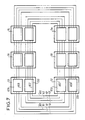
- FIG. 7 schematically represents a network with two rings A1 and A2, with two AS1 and AS2 emergency rings.
- Each station S1 to Sn comprises two couplers CS1 and CS2 identical to the coupler CS in FIG. 4.
- the coupler CS1 is connected to the ring A1, to the emergency ring AS1 and to two detection links 12 and 13;
- the coupler CS2 is connected to the ring A2, to the emergency ring AS2 and to two detection links 12 ′ and 13 ′.
- the couplers CS1 of two adjacent stations are connected by a cord comprising the ring A1, the emergency ring AS1 and the two detection links 12 and 13;
- the couplers CS2 of two adjacent stations are connected by another cord comprising the ring A2, the emergency ring AS2 and the two detection links 12 ′ and 13 ′.
- Each cord is equipped at its ends with a connector cooperating with a connector of the coupler to which it is connected, as in FIG. 4.
- the emergency rings AS1 and AS2 have been shown, to distinguish them from the rings A1, A2, since the couplers of each station ensure the metallic continuity of said emergency rings in normal operation, that is to say when there is no break or absence of cord between two stations, and that no coupler is removed in the stations.
- Figures 5 and 6 which represent the topology of a network with a ring in the case of a broken cord, Figure 5, and in the case of the absence of a coupler, Figure 6, are valid for each of the rings of a network with two rings, FIG. 7 since for each ring associated with its spare ring we have the same configurations as for ring A and the spare ring AS shown in FIGS. 5 and 6.
- the self-healing device of the invention therefore makes it possible to ensure the exchange of information between the stations in the event of a break or withdrawal of a cord between two stations, or during the withdrawal of a coupler from a station; the functioning of the self-healing circuits is linked only to the presence or rupture of the detection links 12 and 13, or 12 ′ and 13 ′, and is independent of the direction of circulation of the information on the or the rings.
- the upstream and downstream designations used to distinguish the self-healing circuits of a station are only intended to facilitate description, the upstream circuit being connected to a previous station and the downstream circuit to a next station.
- the self-healing device of the invention therefore operates regardless of the direction of information flow on the ring, or the two rings, and in the latter case the information can flow in the opposite direction in the two rings.
- cords connected to the upstream and downstream self-healing circuits have different references, this only for the purpose of facilitating the description, but obviously the cords 10 and 11 are identical; in FIG. 7, two adjacent stations are connected by two cords identical to cords 10 and 11.
- the self-healing device of the invention allows the extension of the number of stations without interrupting the exchanges between the stations, whether it is a one-ring network, FIG. 3, or a two-ring network. , figure 7.
- the extension consists in adding to the n existing stations one or more other stations; these additional stations can take place anywhere, between two stations, the problem of the extension being independent of the place where the additional station (s) are introduced in the network.
- the control circuits 7 of each downstream self-healing circuit of the station Si, of the upstream and downstream self-healing circuits of the additional station, and of each upstream self-healing circuit of the station S (i + 1) detect continuity detection links and control, in each of these self-healing circuits, the relay 6, the movable contacts of which pass into the rest position, which establishes the metallic continuity of each ring and of each emergency ring between the station Si and the additional station on the one hand, and the additional station and the station S (i + 1) on the other.
- the withdrawal of a station is the reverse operation of the extension; the station to be removed is disconnected from the previous station and from the next station, and said previous and next stations are linked together by one or two cords.
- control circuit 7 In a self-healing circuit, the control circuit 7 therefore controls the relay 6 to put its movable contacts in the working position when the detection link which connects said control circuit to a self-healing circuit of another station is broken; this rupture is caused either by the rupture or withdrawal of the cord connecting the two stations, or by the withdrawal of the coupler from the other station.
- the self-healing device of the invention therefore makes it possible, for repair or maintenance reasons, to be able to replace a coupler from one station without stopping the operation of the other stations, and in the case of a link with two rings without stopping the operation of the station from which a coupler is removed, said station remaining accessible by the other ring.
- the micro-cuts generated during the removal, or the insertion, of a coupler are absorbed by the protocol which governs the exchange of information on the ring, or the rings.
- the device also makes it possible, for reasons of capacity expansion, to be able to increase the number of stations without stopping the operation of stations already in service; it also makes it possible, in the event of a break in a cord connecting two stations, to maintain the operation of the other stations, in the case of a link with a ring, and of all the stations in the case of a link with two rings, the station became inaccessible by a ring following the rupture of a cord remaining accessible by the other ring.
Landscapes
- Engineering & Computer Science (AREA)
- Computer Networks & Wireless Communication (AREA)
- Signal Processing (AREA)
- Small-Scale Networks (AREA)
- Motorcycle And Bicycle Frame (AREA)
- Electrotherapy Devices (AREA)
- Superheterodyne Receivers (AREA)
- Hooks, Suction Cups, And Attachment By Adhesive Means (AREA)
- Massaging Devices (AREA)
- Position Input By Displaying (AREA)
Priority Applications (1)
| Application Number | Priority Date | Filing Date | Title |
|---|---|---|---|
| AT89122811T ATE99477T1 (de) | 1988-12-12 | 1989-12-11 | Selbstheilende vorrichtung einer schleifenverbindung. |
Applications Claiming Priority (2)
| Application Number | Priority Date | Filing Date | Title |
|---|---|---|---|
| FR8816316A FR2640447B1 (fr) | 1988-12-12 | 1988-12-12 | Dispositif d'autocicatrisation d'une liaison en anneau |
| FR8816316 | 1988-12-12 |
Publications (2)
| Publication Number | Publication Date |
|---|---|
| EP0374670A1 true EP0374670A1 (de) | 1990-06-27 |
| EP0374670B1 EP0374670B1 (de) | 1993-12-29 |
Family
ID=9372834
Family Applications (1)
| Application Number | Title | Priority Date | Filing Date |
|---|---|---|---|
| EP89122811A Expired - Lifetime EP0374670B1 (de) | 1988-12-12 | 1989-12-11 | Selbstheilende Vorrichtung einer Schleifenverbindung |
Country Status (7)
| Country | Link |
|---|---|
| US (1) | US5081452A (de) |
| EP (1) | EP0374670B1 (de) |
| AT (1) | ATE99477T1 (de) |
| CA (1) | CA2005055A1 (de) |
| DE (1) | DE68911889T2 (de) |
| ES (1) | ES2047648T3 (de) |
| FR (1) | FR2640447B1 (de) |
Cited By (2)
| Publication number | Priority date | Publication date | Assignee | Title |
|---|---|---|---|---|
| EP0531059A1 (de) * | 1991-09-03 | 1993-03-10 | The Whitaker Corporation | Vorrichtung zur Fehlererkennung und Rekonfigurierung von Hauptleitungen in einem ringförmigen Kommunikationsnetzwerk |
| EP2204706A1 (de) * | 2008-12-31 | 2010-07-07 | LS Industrial Systems Co., Ltd | Datenweiterleitungsvorrichtung für Kommunikationsmodule |
Families Citing this family (28)
| Publication number | Priority date | Publication date | Assignee | Title |
|---|---|---|---|---|
| GB9201126D0 (en) * | 1992-01-20 | 1992-03-11 | Madge Networks Ltd | Communication system |
| US5394401A (en) * | 1993-04-14 | 1995-02-28 | Digital Equipment Corporation | Arrangement for a token ring communications network |
| US5353286A (en) * | 1993-04-14 | 1994-10-04 | Digital Equipment Corporation | Configuration controller for a communications network |
| US5523998A (en) * | 1993-04-14 | 1996-06-04 | Digital Equipment Corporation | Configuration controller for establishing timing signals of a communications network |
| US5384779A (en) * | 1993-04-14 | 1995-01-24 | Digital Equipment Corporation | State machines for configuration of a communications network |
| GB9403223D0 (en) * | 1994-02-19 | 1994-04-13 | Plessey Telecomm | Telecommunications network including remote channel switching protection apparatus |
| US5551532A (en) * | 1994-02-28 | 1996-09-03 | Otis Elevator Company | Method for transmitting messages in an elevator communications system |
| US5528594A (en) * | 1994-12-22 | 1996-06-18 | International Business Machines Corporation | Method and system for implementing sub-tokens on a token ring network |
| JPH11508427A (ja) * | 1995-06-26 | 1999-07-21 | テレフオンアクチーボラゲツト エル エム エリクソン(パブル) | 自己回復網 |
| US5777761A (en) * | 1995-12-22 | 1998-07-07 | Mci Communications Corporation | System and method for photonic facility and line protection switching using wavelength translation |
| US5731887A (en) * | 1995-12-22 | 1998-03-24 | Mci Communications Corporation | System and method for photonic facility and line protection switching |
| US6005694A (en) * | 1995-12-28 | 1999-12-21 | Mci Worldcom, Inc. | Method and system for detecting optical faults within the optical domain of a fiber communication network |
| US6108113A (en) * | 1995-12-29 | 2000-08-22 | Mci Communications Corporation | Method and system for transporting ancillary network data |
| US6285475B1 (en) | 1995-12-29 | 2001-09-04 | Mci Communications Corporation | Method and system for detecting optical faults in a network fiber link |
| US5884017A (en) * | 1995-12-29 | 1999-03-16 | Mci Communications Corporation | Method and system for optical restoration tributary switching in a fiber network |
| JP3640721B2 (ja) * | 1996-02-05 | 2005-04-20 | 富士通株式会社 | リング伝送システムの異方式移行方法および伝送装置 |
| US5903370A (en) * | 1996-06-28 | 1999-05-11 | Mci Communications Corporation | System for an optical domain |
| US6115155A (en) | 1996-10-29 | 2000-09-05 | Chorum Technologies Inc. | System for dealing with faults in an optical link |
| US6760302B1 (en) | 1996-12-20 | 2004-07-06 | The Trustees Of Columbia University In The City Of New York | Automatic protection switching system in a network |
| WO1998028872A1 (en) * | 1996-12-20 | 1998-07-02 | The Trustees Of Columbia University In The City Of New York | Automatic protection switching system in a network |
| US6295146B1 (en) * | 1998-01-14 | 2001-09-25 | Mci Communications Corporation | System and method for sharing a spare channel among two or more optical ring networks |
| JPH11313095A (ja) * | 1998-04-28 | 1999-11-09 | Nec Corp | リングネットワークシステム、そのプロテクション方法及びプロテクション処理プログラム記録媒体 |
| US6331905B1 (en) | 1999-04-01 | 2001-12-18 | The Trustees Of Columbia University In The City Of New York | Network switch failure restoration |
| IT1316761B1 (it) * | 2000-02-18 | 2003-05-12 | Cit Alcatel | Meccanismo di protezione di reti in fibra ottica con topologia lineare |
| US7254663B2 (en) * | 2004-07-22 | 2007-08-07 | International Business Machines Corporation | Multi-node architecture with daisy chain communication link configurable to operate in unidirectional and bidirectional modes |
| US7334070B2 (en) * | 2004-10-29 | 2008-02-19 | International Business Machines Corporation | Multi-channel memory architecture for daisy chained arrangements of nodes with bridging between memory channels |
| DE102006055889B3 (de) * | 2006-11-27 | 2008-05-29 | Beckhoff Automation Gmbh | Kommunikationssystem mit einer Master-Slave-Struktur |
| DE102006055887A1 (de) * | 2006-11-27 | 2008-05-29 | Beckhoff Automation Gmbh | Kommunikationssystem mit einer Master-Slave-Struktur |
Citations (1)
| Publication number | Priority date | Publication date | Assignee | Title |
|---|---|---|---|---|
| EP0086577A1 (de) * | 1982-02-08 | 1983-08-24 | Racal-Milgo Limited | Kommunikationssystem |
Family Cites Families (9)
| Publication number | Priority date | Publication date | Assignee | Title |
|---|---|---|---|---|
| EP0060307B1 (de) * | 1981-03-12 | 1985-07-17 | International Business Machines Corporation | Verfahren zum Anschliessen oder Abtrennen gewählter Stationen in einem Ring-Nachrichtensystem und Ring-Nachrichtensystem mit selektiv anschliessbaren Stationen |
| JPS59107665A (ja) * | 1982-12-13 | 1984-06-21 | Hitachi Ltd | ル−プ伝送システムの切換方式 |
| DE3427891A1 (de) * | 1984-07-28 | 1986-01-30 | Philips Patentverwaltung Gmbh, 2000 Hamburg | Anordnung zur informationsuebertragung mit rekonfiguration |
| US4777330A (en) * | 1985-02-15 | 1988-10-11 | Hitachi, Ltd. | Network system diagnosis system |
| DE3578905D1 (de) * | 1985-04-23 | 1990-08-30 | Ibm | Nebenanschlussanordnung und verfahren zum stationsanschliessen fuer ein ringkommunikationssystem. |
| US4847610A (en) * | 1986-07-31 | 1989-07-11 | Mitsubishi Denki K.K. | Method of restoring transmission line |
| JPS6346029A (ja) * | 1986-08-13 | 1988-02-26 | Hitachi Ltd | ル−プバツク制御方式 |
| GB8709771D0 (en) * | 1987-04-24 | 1987-05-28 | Madge Networks Ltd | Token ring expander/hub |
| JPH0744556B2 (ja) * | 1987-06-27 | 1995-05-15 | 株式会社日立製作所 | 集線装置 |
-
1988
- 1988-12-12 FR FR8816316A patent/FR2640447B1/fr not_active Expired - Lifetime
-
1989
- 1989-12-11 EP EP89122811A patent/EP0374670B1/de not_active Expired - Lifetime
- 1989-12-11 CA CA002005055A patent/CA2005055A1/fr not_active Abandoned
- 1989-12-11 AT AT89122811T patent/ATE99477T1/de active
- 1989-12-11 ES ES89122811T patent/ES2047648T3/es not_active Expired - Lifetime
- 1989-12-11 DE DE89122811T patent/DE68911889T2/de not_active Expired - Fee Related
-
1991
- 1991-06-07 US US07/711,711 patent/US5081452A/en not_active Expired - Lifetime
Patent Citations (1)
| Publication number | Priority date | Publication date | Assignee | Title |
|---|---|---|---|---|
| EP0086577A1 (de) * | 1982-02-08 | 1983-08-24 | Racal-Milgo Limited | Kommunikationssystem |
Non-Patent Citations (1)
| Title |
|---|
| PATENT ABSTRACTS OF JAPAN, vol. 8, no. 226 (E-272)[1663], 17 octobre 1984; & JP-A-59 107 665 (HITACHI SEISAKUSHO K.K.) 21-06-1984 * |
Cited By (3)
| Publication number | Priority date | Publication date | Assignee | Title |
|---|---|---|---|---|
| EP0531059A1 (de) * | 1991-09-03 | 1993-03-10 | The Whitaker Corporation | Vorrichtung zur Fehlererkennung und Rekonfigurierung von Hauptleitungen in einem ringförmigen Kommunikationsnetzwerk |
| US5282237A (en) * | 1991-09-03 | 1994-01-25 | The Whitaker Corporation | Trunk cable fault detection and reconfiguration arrangement in a ring commnications network |
| EP2204706A1 (de) * | 2008-12-31 | 2010-07-07 | LS Industrial Systems Co., Ltd | Datenweiterleitungsvorrichtung für Kommunikationsmodule |
Also Published As
| Publication number | Publication date |
|---|---|
| EP0374670B1 (de) | 1993-12-29 |
| FR2640447B1 (fr) | 1991-01-25 |
| DE68911889D1 (de) | 1994-02-10 |
| ES2047648T3 (es) | 1994-03-01 |
| FR2640447A1 (fr) | 1990-06-15 |
| ATE99477T1 (de) | 1994-01-15 |
| DE68911889T2 (de) | 1994-04-21 |
| CA2005055A1 (fr) | 1990-06-12 |
| US5081452A (en) | 1992-01-14 |
Similar Documents
| Publication | Publication Date | Title |
|---|---|---|
| EP0374670B1 (de) | Selbstheilende Vorrichtung einer Schleifenverbindung | |
| CA1223933A (en) | Transmission line control system | |
| EP0032327B1 (de) | Verfahren und Anlage zur Sicherung eines digitalen Übertragungskabels | |
| FR2680067A1 (fr) | Procede de controle d'un repartiteur de lignes; cable auxiliaire, connecteur et repartiteur pour la mise en óoeuvre de ce procede. | |
| EP0579529B1 (de) | Vorrichtung zum Verbinden eines Terminals an ein mindestens aus einem Ring bestehendes lokales Netz | |
| FR2610463A1 (fr) | Circuit de commutation d'alimentation pour cable sous-marin | |
| WO1998002951A1 (fr) | Appareillage electrique debrochable | |
| EP0454036B1 (de) | Verfahren und Anordnung für die Rückkehr zu einer normalen Verbindung nach Benutzung einer Hilfsverbindung in einem Datenübertragungssystem | |
| EP0528732A1 (de) | Bildfernsprechverfahren und -gerät | |
| FR2812987A1 (fr) | Procede, dispositif et systeme de commutation de lignes d'alimentation en energie electrique | |
| FR2848756A1 (fr) | Reseau ethernet | |
| US20080291844A1 (en) | Direct Sequential Network Addressing (Dsna) | |
| EP2104277A1 (de) | Störungserkennung und Isolierung eines nachgeschalteten Highspeed-CAN-Netzes | |
| EP0749174A1 (de) | Schalternetzwerk für die Verbindung von redundanten Kanälen | |
| EP0275779B1 (de) | Gerichtete Schutzrelaiseinrichtung, bestehend aus mehreren Typen | |
| FR2896935A1 (fr) | Dispositif de connexion electrique d'une ligne telephonique analogique bifilaire et desserte interne associee. | |
| JP2788408B2 (ja) | 通信システム | |
| EP0395483B1 (de) | Doppelringkommunikationssystem | |
| BE898337A (fr) | Appareillage pour l'essai de sonneries d'appel de lignes d'abonnés. | |
| EP0750435A1 (de) | Doppelpoliges Umschalternetzwerk zum Verbinden redundanter Kanäle | |
| FR2550401A1 (fr) | Outil d'aide a l'exploitation de systemes de communication de donnees sur reseau local et systeme incorporant un tel outil | |
| FR2696048A1 (fr) | Dispositif de connexion pour installation de transmission de signaux. | |
| EP0629070B1 (de) | Transkodierung/kodierung von Flag-bytes in einer HDLC-Datenverbindung | |
| EP0966176A1 (de) | System zur Datenübertragung zwischen mehreren Stationen | |
| JP3353573B2 (ja) | 電流差動継電装置における同期確立の判定方法 |
Legal Events
| Date | Code | Title | Description |
|---|---|---|---|
| PUAI | Public reference made under article 153(3) epc to a published international application that has entered the european phase |
Free format text: ORIGINAL CODE: 0009012 |
|
| AK | Designated contracting states |
Kind code of ref document: A1 Designated state(s): AT BE CH DE ES FR GB IT LI NL SE |
|
| 17P | Request for examination filed |
Effective date: 19901227 |
|
| 17Q | First examination report despatched |
Effective date: 19930216 |
|
| GRAA | (expected) grant |
Free format text: ORIGINAL CODE: 0009210 |
|
| AK | Designated contracting states |
Kind code of ref document: B1 Designated state(s): AT BE CH DE ES FR GB IT LI NL SE |
|
| REF | Corresponds to: |
Ref document number: 99477 Country of ref document: AT Date of ref document: 19940115 Kind code of ref document: T |
|
| REF | Corresponds to: |
Ref document number: 68911889 Country of ref document: DE Date of ref document: 19940210 |
|
| GBT | Gb: translation of ep patent filed (gb section 77(6)(a)/1977) |
Effective date: 19940121 |
|
| REG | Reference to a national code |
Ref country code: ES Ref legal event code: FG2A Ref document number: 2047648 Country of ref document: ES Kind code of ref document: T3 |
|
| ITF | It: translation for a ep patent filed | ||
| PLBE | No opposition filed within time limit |
Free format text: ORIGINAL CODE: 0009261 |
|
| STAA | Information on the status of an ep patent application or granted ep patent |
Free format text: STATUS: NO OPPOSITION FILED WITHIN TIME LIMIT |
|
| 26N | No opposition filed | ||
| EAL | Se: european patent in force in sweden |
Ref document number: 89122811.6 |
|
| PGFP | Annual fee paid to national office [announced via postgrant information from national office to epo] |
Ref country code: GB Payment date: 19971113 Year of fee payment: 9 Ref country code: FR Payment date: 19971113 Year of fee payment: 9 |
|
| PGFP | Annual fee paid to national office [announced via postgrant information from national office to epo] |
Ref country code: SE Payment date: 19971124 Year of fee payment: 9 Ref country code: CH Payment date: 19971124 Year of fee payment: 9 |
|
| PGFP | Annual fee paid to national office [announced via postgrant information from national office to epo] |
Ref country code: AT Payment date: 19971126 Year of fee payment: 9 |
|
| PGFP | Annual fee paid to national office [announced via postgrant information from national office to epo] |
Ref country code: DE Payment date: 19971128 Year of fee payment: 9 |
|
| PGFP | Annual fee paid to national office [announced via postgrant information from national office to epo] |
Ref country code: NL Payment date: 19971130 Year of fee payment: 9 |
|
| PGFP | Annual fee paid to national office [announced via postgrant information from national office to epo] |
Ref country code: BE Payment date: 19971208 Year of fee payment: 9 |
|
| PGFP | Annual fee paid to national office [announced via postgrant information from national office to epo] |
Ref country code: ES Payment date: 19971216 Year of fee payment: 9 |
|
| PG25 | Lapsed in a contracting state [announced via postgrant information from national office to epo] |
Ref country code: GB Free format text: LAPSE BECAUSE OF NON-PAYMENT OF DUE FEES Effective date: 19981211 Ref country code: AT Free format text: LAPSE BECAUSE OF NON-PAYMENT OF DUE FEES Effective date: 19981211 |
|
| PG25 | Lapsed in a contracting state [announced via postgrant information from national office to epo] |
Ref country code: SE Free format text: LAPSE BECAUSE OF NON-PAYMENT OF DUE FEES Effective date: 19981212 Ref country code: ES Free format text: LAPSE BECAUSE OF THE APPLICANT RENOUNCES Effective date: 19981212 |
|
| PG25 | Lapsed in a contracting state [announced via postgrant information from national office to epo] |
Ref country code: LI Free format text: LAPSE BECAUSE OF NON-PAYMENT OF DUE FEES Effective date: 19981231 Ref country code: CH Free format text: LAPSE BECAUSE OF NON-PAYMENT OF DUE FEES Effective date: 19981231 Ref country code: BE Free format text: LAPSE BECAUSE OF NON-PAYMENT OF DUE FEES Effective date: 19981231 |
|
| BERE | Be: lapsed |
Owner name: ALCATEL CIT Effective date: 19981231 |
|
| PG25 | Lapsed in a contracting state [announced via postgrant information from national office to epo] |
Ref country code: NL Free format text: LAPSE BECAUSE OF NON-PAYMENT OF DUE FEES Effective date: 19990701 |
|
| GBPC | Gb: european patent ceased through non-payment of renewal fee |
Effective date: 19981211 |
|
| REG | Reference to a national code |
Ref country code: CH Ref legal event code: PL |
|
| PG25 | Lapsed in a contracting state [announced via postgrant information from national office to epo] |
Ref country code: FR Free format text: LAPSE BECAUSE OF NON-PAYMENT OF DUE FEES Effective date: 19990831 |
|
| NLV4 | Nl: lapsed or anulled due to non-payment of the annual fee |
Effective date: 19990701 |
|
| REG | Reference to a national code |
Ref country code: FR Ref legal event code: ST |
|
| PG25 | Lapsed in a contracting state [announced via postgrant information from national office to epo] |
Ref country code: DE Free format text: LAPSE BECAUSE OF NON-PAYMENT OF DUE FEES Effective date: 19991001 |
|
| REG | Reference to a national code |
Ref country code: ES Ref legal event code: FD2A Effective date: 20010402 |
|
| PG25 | Lapsed in a contracting state [announced via postgrant information from national office to epo] |
Ref country code: IT Free format text: LAPSE BECAUSE OF NON-PAYMENT OF DUE FEES;WARNING: LAPSES OF ITALIAN PATENTS WITH EFFECTIVE DATE BEFORE 2007 MAY HAVE OCCURRED AT ANY TIME BEFORE 2007. THE CORRECT EFFECTIVE DATE MAY BE DIFFERENT FROM THE ONE RECORDED. Effective date: 20051211 |