EP0374679A2 - Procédé de préparation d'une lampe à décharge à haute pression à deux culots - Google Patents
Procédé de préparation d'une lampe à décharge à haute pression à deux culots Download PDFInfo
- Publication number
- EP0374679A2 EP0374679A2 EP89122833A EP89122833A EP0374679A2 EP 0374679 A2 EP0374679 A2 EP 0374679A2 EP 89122833 A EP89122833 A EP 89122833A EP 89122833 A EP89122833 A EP 89122833A EP 0374679 A2 EP0374679 A2 EP 0374679A2
- Authority
- EP
- European Patent Office
- Prior art keywords
- tube
- discharge vessel
- pinch
- producing
- lamp
- Prior art date
- Legal status (The legal status is an assumption and is not a legal conclusion. Google has not performed a legal analysis and makes no representation as to the accuracy of the status listed.)
- Granted
Links
- 238000004519 manufacturing process Methods 0.000 title claims description 11
- 238000007789 sealing Methods 0.000 claims abstract description 11
- VYPSYNLAJGMNEJ-UHFFFAOYSA-N silicon dioxide Inorganic materials O=[Si]=O VYPSYNLAJGMNEJ-UHFFFAOYSA-N 0.000 claims abstract description 7
- 239000010453 quartz Substances 0.000 claims abstract description 5
- 239000000126 substance Substances 0.000 claims abstract description 5
- 238000001816 cooling Methods 0.000 claims abstract 2
- 238000005096 rolling process Methods 0.000 claims abstract 2
- 238000000034 method Methods 0.000 claims description 16
- 238000010438 heat treatment Methods 0.000 claims description 9
- IJGRMHOSHXDMSA-UHFFFAOYSA-N Atomic nitrogen Chemical compound N#N IJGRMHOSHXDMSA-UHFFFAOYSA-N 0.000 claims description 8
- 239000007789 gas Substances 0.000 claims description 6
- 238000002844 melting Methods 0.000 claims description 4
- 230000008018 melting Effects 0.000 claims description 4
- 229910052757 nitrogen Inorganic materials 0.000 claims description 4
- 239000000155 melt Substances 0.000 claims 3
- 239000011261 inert gas Substances 0.000 claims 1
- 229910001507 metal halide Inorganic materials 0.000 abstract description 8
- 150000005309 metal halides Chemical class 0.000 abstract description 8
- 238000011010 flushing procedure Methods 0.000 abstract 2
- XKRFYHLGVUSROY-UHFFFAOYSA-N Argon Chemical compound [Ar] XKRFYHLGVUSROY-UHFFFAOYSA-N 0.000 description 6
- 229910052786 argon Inorganic materials 0.000 description 3
- 239000002245 particle Substances 0.000 description 3
- ZOKXTWBITQBERF-UHFFFAOYSA-N Molybdenum Chemical compound [Mo] ZOKXTWBITQBERF-UHFFFAOYSA-N 0.000 description 2
- 238000009826 distribution Methods 0.000 description 2
- 239000000463 material Substances 0.000 description 2
- QSHDDOUJBYECFT-UHFFFAOYSA-N mercury Chemical compound [Hg] QSHDDOUJBYECFT-UHFFFAOYSA-N 0.000 description 2
- 229910052753 mercury Inorganic materials 0.000 description 2
- 229910052750 molybdenum Inorganic materials 0.000 description 2
- 239000011733 molybdenum Substances 0.000 description 2
- 230000003287 optical effect Effects 0.000 description 2
- 230000005855 radiation Effects 0.000 description 2
- 229910052721 tungsten Inorganic materials 0.000 description 2
- 208000025962 Crush injury Diseases 0.000 description 1
- 240000007817 Olea europaea Species 0.000 description 1
- 238000009825 accumulation Methods 0.000 description 1
- 230000002411 adverse Effects 0.000 description 1
- 238000000137 annealing Methods 0.000 description 1
- 238000005452 bending Methods 0.000 description 1
- 238000004140 cleaning Methods 0.000 description 1
- 238000010276 construction Methods 0.000 description 1
- 238000011109 contamination Methods 0.000 description 1
- 238000001704 evaporation Methods 0.000 description 1
- 239000006187 pill Substances 0.000 description 1
- 238000002360 preparation method Methods 0.000 description 1
- 238000007493 shaping process Methods 0.000 description 1
- WFKWXMTUELFFGS-UHFFFAOYSA-N tungsten Chemical compound [W] WFKWXMTUELFFGS-UHFFFAOYSA-N 0.000 description 1
- 239000010937 tungsten Substances 0.000 description 1
Images


Classifications
-
- H—ELECTRICITY
- H01—ELECTRIC ELEMENTS
- H01J—ELECTRIC DISCHARGE TUBES OR DISCHARGE LAMPS
- H01J9/00—Apparatus or processes specially adapted for the manufacture, installation, removal, maintenance of electric discharge tubes, discharge lamps, or parts thereof; Recovery of material from discharge tubes or lamps
- H01J9/24—Manufacture or joining of vessels, leading-in conductors or bases
- H01J9/245—Manufacture or joining of vessels, leading-in conductors or bases specially adapted for gas discharge tubes or lamps
- H01J9/247—Manufacture or joining of vessels, leading-in conductors or bases specially adapted for gas discharge tubes or lamps specially adapted for gas-discharge lamps
Definitions
- the invention relates to the manufacture of a lamp with the features designated in the preamble of the main claim.
- the invention relates in particular to the production of metal halide high-pressure discharge lamps with an electrical power consumption of at most 50 W, as have recently been increasingly proposed for the purpose of general lighting or for use in motor vehicle headlights.
- Such lamps have hitherto been produced by first closing a quartz tube which is open on both sides and then forming the olive-shaped shape at the location of the future discharge vessel by collecting the quartz glass. Then the tube end, which was initially closed, is opened again in further work steps and a pump tube is attached to the center of the discharge vessel.
- this object is achieved by the sequence of work steps set out in the main claim. Further details for the production of the metal halide high-pressure discharge lamps can be found in the subclaims. Since the work steps of filling and closing the discharge vessel take place in the high-purity atmosphere of the glovebox, contamination by foreign gases such as H2, O2 or H2O can be reduced to a minimum. By heating the still open tube inside the glovebox, the particle density in this area is reduced. This creates - after the sealing melting by means of a plasma torch in the glovebox and after the discharge vessel has cooled - a certain negative pressure inside, which, in conjunction with the temperature reduction to approx. ⁇ 100 ° C, enables the second pinch to be produced outside the glovebox.
- the process time is considerably shortened and the entire production process is simplified. Because of the there are no different wall thicknesses or inhomogeneities of any other type, which means that the radiation emission from the lamp is much more uniform than in the known lamps with a pump tube.
- the lamp is therefore particularly suitable for use in optical systems, for example in motor vehicle headlights, in which extremely precise adjustment and arrangement of the light / dark boundary are important.
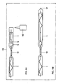
- FIG. 1a shows the tube 1 made of quartz glass cut to a length of approximately 150 mm.
- the outside diameter of the tube is approx. 4.5 mm, the inside diameter d is approx. 2 mm.
- both constrictions 4, 5 are placed in the center and at a defined distance from one another by means of the forming roller 3 (FIG. 1b).
- a nitrogen stream N 2 is passed through the tube 1 at a rate of 10 l / h from one side.
- the future discharge vessel 6 (FIG. 1c) is precisely delimited in its length of approximately 7.5 mm.
- the constriction 4 has a smaller clear diameter than the constriction 5. This results in a gas accumulation p of the nitrogen stream N 2 between the two constrictions in the heated area of the future discharge vessel 6, so that this area is somewhat inflated and its olive shape with an outer diameter of approx .5.5 mm.
- the prefabricated electrode system (FIG. 2) is squeezed into that end of the tube 1 which has the constriction 4 with the smaller diameter.
- the electrode system consists of an electrode 7 made of tungsten, a sealing film 8 made of molybdenum and a power supply 9 made of molybdenum.
- the electrode 7 is provided with a ball 10 at its end arranged in the discharge vessel 6.
- the power supply line 9 is bent in a zigzag shape in the yz plane, the angle ⁇ by which the curved power supply line 9 deviates from the xz plane being less than 45 °, preferably approximately 20 ° -30 °.
- the height h that is the amount by which the reversal point 11 of the curved power supply 9 deviates from the xz plane, is greater than half the inner diameter d of the tube 1. In practice, a ratio corresponding to h ⁇ 0.55 d proven.
- the you tion film 8 is aligned in the xz-plane, that is perpendicular to the yz-plane of the curved power supply 9.
- An electrode system shaped in this way holds itself within the tube 1 by the kinking or reversal points 11 of the power supply 9 being clamped against the inner wall of the tube. Once adjusted to its predetermined position, the electrode system maintains it until it is finally fixed.
- each power supply 9 To securely support the power supply 9 on the inner wall of the tube 1, at least three kink or reversal points 11 are attached to each power supply 9.
- a power supply 9 designed in this way centers itself in the axis of the tube 1.
- the electrode 7 in the discharge vessel 6 is also automatically centered in the x coordinate of the sealing film 8. Any possible decentration perpendicular to the plane of the sealing film 8, that is to say in the y coordinate, for example by bending the sealing film 8, is compensated for during the squeezing process.
- the first pinch 12 is then produced.
- the tube 1 in the area of the sealing film 8 is brought to a temperature of above approximately 2200 ° C. which is suitable for the deformation.
- an argon flow is passed through the preformed tube 1.
- the first pinch 12 is produced.
- the pinch that is adjacent to the constriction 4 with the smaller diameter is first sealed.
- the production of the pinch itself is a process known to the person skilled in lamp construction and is not shown separately in the figures.
- the tube 1 provided with the first pinch 12 is now subjected to high-vacuum annealing at> 400 ° C. and ⁇ 5 ⁇ 10 ⁇ 5 mbar when it is introduced into the glove box for cleaning.
- the glovebox 13 is filled with argon.
- the filling pressure does not deviate from the surrounding atmospheric pressure by more than a few 10 mbar.
- the argon filling gas of the glovebox 13 corresponds to the future filling gas of the metal halide high-pressure discharge lamp.
- the work steps within the glove box 13 are shown in FIG. 4.
- FIG. 4a shows the lamp of FIG. 3 pinched on one side in the glovebox 13.
- the filling substances consisting of a metal halide pill 14 and a mercury ball 15, and first the second electrode system (FIG. 4b) introduced.
- the filling substances fall through the still open constriction 5 with the larger diameter into the discharge vessel 6.
- the electrode system is, as before during the preparation for the first squeeze 12, adjusted in its self-retaining position at its predetermined position, so that the electrode 7 within of the discharge vessel 6 is arranged and the distance between the balls 10 of the two electrodes 7 is given its intended value.
- the open tube 1 is heated with a heating device. This causes a reduction in the particle density in the heated area.
- the quartz tube 1 is then sealed at its open end inside the glovebox 13 by means of a plasma torch 16 or a laser (FIG. 4c), so that only one melting tip 17 (FIG. 4d) remains.
- a plasma torch 16 or a laser FIG. 4c
- the lamp thus prefabricated has cooled down Due to the reduced particle density inside the discharge vessel there is a filling pressure which is approx. 300 mbar below the surrounding atmospheric pressure.
- the prefabricated lamp is now removed from the glovebox 13.
- the area around the sealing film 8 of the second electrode system is heated to the pinch temperature of approximately 2200 ° C. and the second pinch 18 (FIG. 5) is applied by squeezing the second electrode system.
- the area of the discharge vessel 6 is cooled to ⁇ 100 ° C. by means of cooled nitrogen in order to prevent the metal halide 14 and mercury 15 from evaporating.
- the lamp is removed from the squeezing device and the tube ends 1 projecting beyond the squeezes 12, 18 are removed.
- the zigzag part of the power supply lines 9 can also be removed.
- a finished metal halide high-pressure discharge lamp 19 is shown in FIG. 5.
Landscapes
- Engineering & Computer Science (AREA)
- Manufacturing & Machinery (AREA)
- Manufacture Of Electron Tubes, Discharge Lamp Vessels, Lead-In Wires, And The Like (AREA)
- Vessels And Coating Films For Discharge Lamps (AREA)
Applications Claiming Priority (2)
| Application Number | Priority Date | Filing Date | Title |
|---|---|---|---|
| DE3842769 | 1988-12-19 | ||
| DE3842769A DE3842769A1 (de) | 1988-12-19 | 1988-12-19 | Verfahren zur herstellung einer zweiseitigen hochdruckentladungslampe |
Publications (3)
| Publication Number | Publication Date |
|---|---|
| EP0374679A2 true EP0374679A2 (fr) | 1990-06-27 |
| EP0374679A3 EP0374679A3 (fr) | 1991-05-08 |
| EP0374679B1 EP0374679B1 (fr) | 1995-03-15 |
Family
ID=6369557
Family Applications (1)
| Application Number | Title | Priority Date | Filing Date |
|---|---|---|---|
| EP89122833A Expired - Lifetime EP0374679B1 (fr) | 1988-12-19 | 1989-12-11 | Procédé de préparation d'une lampe à décharge à haute pression à deux culots |
Country Status (5)
| Country | Link |
|---|---|
| EP (1) | EP0374679B1 (fr) |
| JP (1) | JP2804134B2 (fr) |
| DD (1) | DD290504A5 (fr) |
| DE (2) | DE3842769A1 (fr) |
| HU (1) | HU203170B (fr) |
Cited By (5)
| Publication number | Priority date | Publication date | Assignee | Title |
|---|---|---|---|---|
| EP0892423A3 (fr) * | 1997-07-17 | 1999-09-22 | Ushiodenki Kabushiki Kaisha | Lampe à décharge du type à arc court et son procédé de fabrication |
| EP0944109A1 (fr) * | 1998-03-16 | 1999-09-22 | Matsushita Electric Industrial Co., Ltd. | Lampe à décharge et sa méthode de fabrication |
| WO2005122206A3 (fr) * | 2004-06-09 | 2008-03-06 | Patent Treuhand Ges Fuer Elektrische Gluehlampen Mbh | Procede d'usinage d'une lampe et lampe usinee selon un tel procede |
| WO2009115118A1 (fr) * | 2008-03-19 | 2009-09-24 | Osram Gesellschaft mit beschränkter Haftung | Lampe à décharge et procédé de fabrication d'une lampe à décharge |
| CN107029635A (zh) * | 2017-05-25 | 2017-08-11 | 桂林理工大学 | 一种在真空环境下制备化合物的方法及装置 |
Families Citing this family (1)
| Publication number | Priority date | Publication date | Assignee | Title |
|---|---|---|---|---|
| GB2423862A (en) | 2005-03-04 | 2006-09-06 | Heraeus Noblelight Ltd | High-pressure discharge lamp having constructional details for reducing devitrification of glass |
Family Cites Families (9)
| Publication number | Priority date | Publication date | Assignee | Title |
|---|---|---|---|---|
| US3305289A (en) * | 1963-05-09 | 1967-02-21 | Gen Electric | Electric lamp manufacture |
| US3689799A (en) * | 1970-09-14 | 1972-09-05 | Gen Electric | Method of dosing lamps |
| DE2127526A1 (de) * | 1971-06-03 | 1972-12-14 | Licentia Gmbh | Verfahren zur Durchfuhrung des Verfahrens zum Erzeugen eines Hochvakuums und Vornch |
| JPS51128179A (en) * | 1975-04-30 | 1976-11-08 | Iwasaki Electric Co Ltd | Discharge lamp manufacturing method |
| JPS6057654B2 (ja) * | 1980-12-26 | 1985-12-16 | 株式会社東芝 | 管球の封止加工方法 |
| JPS60127633A (ja) * | 1983-12-12 | 1985-07-08 | Toshiba Corp | 金属蒸気放電灯の製造方法 |
| SE457033B (sv) * | 1985-05-23 | 1988-11-21 | Lumalampan Ab | Kompaktlysroer |
| HU207175B (en) * | 1986-02-12 | 1993-03-01 | Tungsram Reszvenytarsasag | Device for manufacturing discharge tube of a sodium vapour discharge lamp |
| DE3842770A1 (de) | 1988-12-19 | 1990-06-21 | Patent Treuhand Ges Fuer Elektrische Gluehlampen Mbh | Verfahren zur herstellung einer zweiseitigen hochdruckentladungslampe |
-
1988
- 1988-12-19 DE DE3842769A patent/DE3842769A1/de not_active Withdrawn
-
1989
- 1989-12-11 DE DE58909112T patent/DE58909112D1/de not_active Expired - Lifetime
- 1989-12-11 EP EP89122833A patent/EP0374679B1/fr not_active Expired - Lifetime
- 1989-12-18 DD DD89335842A patent/DD290504A5/de not_active IP Right Cessation
- 1989-12-18 HU HU896665A patent/HU203170B/hu not_active IP Right Cessation
- 1989-12-19 JP JP1327508A patent/JP2804134B2/ja not_active Expired - Lifetime
Cited By (6)
| Publication number | Priority date | Publication date | Assignee | Title |
|---|---|---|---|---|
| EP0892423A3 (fr) * | 1997-07-17 | 1999-09-22 | Ushiodenki Kabushiki Kaisha | Lampe à décharge du type à arc court et son procédé de fabrication |
| EP0944109A1 (fr) * | 1998-03-16 | 1999-09-22 | Matsushita Electric Industrial Co., Ltd. | Lampe à décharge et sa méthode de fabrication |
| US6791271B2 (en) | 1998-03-16 | 2004-09-14 | Matsushita Electric Industrial Co., Ltd. | Discharge lamp and method of producing the same |
| WO2005122206A3 (fr) * | 2004-06-09 | 2008-03-06 | Patent Treuhand Ges Fuer Elektrische Gluehlampen Mbh | Procede d'usinage d'une lampe et lampe usinee selon un tel procede |
| WO2009115118A1 (fr) * | 2008-03-19 | 2009-09-24 | Osram Gesellschaft mit beschränkter Haftung | Lampe à décharge et procédé de fabrication d'une lampe à décharge |
| CN107029635A (zh) * | 2017-05-25 | 2017-08-11 | 桂林理工大学 | 一种在真空环境下制备化合物的方法及装置 |
Also Published As
| Publication number | Publication date |
|---|---|
| HU896665D0 (en) | 1990-02-28 |
| HUT52893A (en) | 1990-08-28 |
| DE3842769A1 (de) | 1990-06-21 |
| DE58909112D1 (de) | 1995-04-20 |
| EP0374679B1 (fr) | 1995-03-15 |
| EP0374679A3 (fr) | 1991-05-08 |
| HU203170B (en) | 1991-05-28 |
| DD290504A5 (de) | 1991-05-29 |
| JPH02223131A (ja) | 1990-09-05 |
| JP2804134B2 (ja) | 1998-09-24 |
Similar Documents
| Publication | Publication Date | Title |
|---|---|---|
| DE69403176T2 (de) | Elektrische Lampe | |
| DE2212536C2 (de) | Verfahren zur Herstellung von Leuchtstofflampen | |
| DE2835904C2 (de) | Verwendung einer Baueinheit aus Elektrode und Zuleitung | |
| EP0386588B1 (fr) | Lampe à décharge à basse pression de mercure | |
| DE19710204A1 (de) | Bogenentladungsröhre, die mit einem Paar von Molybdänfolien versehen ist, und zugehöriges Herstellungsverfahren | |
| EP0374679B1 (fr) | Procédé de préparation d'une lampe à décharge à haute pression à deux culots | |
| DE3029824A1 (de) | Hochdruckentladungslampe | |
| EP0374677B1 (fr) | Procédé de préparation d'une lampe à décharge à haute pression à deux culots | |
| DE69712833T2 (de) | Bogenentladungsröhre für Entladungslampenvorrichtung | |
| EP0374676B1 (fr) | Procédé de préparation d'une lampe à décharge à haute pression à deux culots | |
| EP0813229A2 (fr) | Procédé de fabrication d'une lampe à incandescence halogène | |
| DE2732060C2 (de) | Elektrische Leuchtstofflampe | |
| EP0591777A2 (fr) | Méthode de fabrication d'une lampe à décharge à haute pression de faible puissance à pincement unique et lampes à décharge à haute pression | |
| DE3112821A1 (de) | Elektrische lampe mit einer als quetschung ausgebildeten gefaesseinschmelzung sowie vorrichtung und verfahren zur herstellung | |
| DE3320919C2 (fr) | ||
| CH621889A5 (fr) | ||
| EP0219860B1 (fr) | Méthode de fabrication d'une lampe à décharge à haute pression à halogénures de métal à pincement unique et une lampe fabriquée suivant cette méthode | |
| EP0369370B1 (fr) | Méthode de fabrication d'une enceinte de lampe | |
| DE2529004A1 (de) | Gegenstand mit einem glasteil, in den ein metallteil eingeschmolzen ist | |
| DE975461C (de) | Elektronenstrahlroehre, insbesondere Fernsehbildroehre, mit einem aus Metall bestehenden Roehrenkolben | |
| DE19603301C2 (de) | Elektrische Lampe mit Molybdänfoliendurchführungen für ein Lampengefäß aus Quarzglas | |
| DE10117664C1 (de) | Rohrstutzen zum Leiten von oder Eintauchen in Glasschmelzen sowie zu deren Erhitzung und die Verwendung des Rohrstutzens | |
| DE9015032U1 (de) | Metallfolie zur Verwendung als Stromleiter bei elektrischen Lampen | |
| DE19647827B4 (de) | Verfahren zur Herstellung einer Leuchtstofflampe | |
| DE1004732B (de) | Verfahren zur Herstellung einer teilweise verspiegelten, rohrfoermigen Gluehlampe |
Legal Events
| Date | Code | Title | Description |
|---|---|---|---|
| PUAI | Public reference made under article 153(3) epc to a published international application that has entered the european phase |
Free format text: ORIGINAL CODE: 0009012 |
|
| AK | Designated contracting states |
Kind code of ref document: A2 Designated state(s): DE FR GB IT NL SE |
|
| 17P | Request for examination filed |
Effective date: 19901220 |
|
| PUAL | Search report despatched |
Free format text: ORIGINAL CODE: 0009013 |
|
| AK | Designated contracting states |
Kind code of ref document: A3 Designated state(s): DE FR GB IT NL SE |
|
| 17Q | First examination report despatched |
Effective date: 19930628 |
|
| GRAA | (expected) grant |
Free format text: ORIGINAL CODE: 0009210 |
|
| AK | Designated contracting states |
Kind code of ref document: B1 Designated state(s): DE FR GB IT NL SE |
|
| REF | Corresponds to: |
Ref document number: 58909112 Country of ref document: DE Date of ref document: 19950420 |
|
| ITF | It: translation for a ep patent filed | ||
| ET | Fr: translation filed | ||
| GBT | Gb: translation of ep patent filed (gb section 77(6)(a)/1977) |
Effective date: 19950605 |
|
| PLBE | No opposition filed within time limit |
Free format text: ORIGINAL CODE: 0009261 |
|
| STAA | Information on the status of an ep patent application or granted ep patent |
Free format text: STATUS: NO OPPOSITION FILED WITHIN TIME LIMIT |
|
| 26N | No opposition filed | ||
| REG | Reference to a national code |
Ref country code: GB Ref legal event code: IF02 |
|
| PGFP | Annual fee paid to national office [announced via postgrant information from national office to epo] |
Ref country code: NL Payment date: 20051205 Year of fee payment: 17 |
|
| PGFP | Annual fee paid to national office [announced via postgrant information from national office to epo] |
Ref country code: GB Payment date: 20051208 Year of fee payment: 17 Ref country code: SE Payment date: 20051208 Year of fee payment: 17 |
|
| PGFP | Annual fee paid to national office [announced via postgrant information from national office to epo] |
Ref country code: FR Payment date: 20051216 Year of fee payment: 17 |
|
| PG25 | Lapsed in a contracting state [announced via postgrant information from national office to epo] |
Ref country code: SE Free format text: LAPSE BECAUSE OF NON-PAYMENT OF DUE FEES Effective date: 20061212 |
|
| PGFP | Annual fee paid to national office [announced via postgrant information from national office to epo] |
Ref country code: IT Payment date: 20061231 Year of fee payment: 18 |
|
| PG25 | Lapsed in a contracting state [announced via postgrant information from national office to epo] |
Ref country code: NL Free format text: LAPSE BECAUSE OF NON-PAYMENT OF DUE FEES Effective date: 20070701 |
|
| EUG | Se: european patent has lapsed | ||
| GBPC | Gb: european patent ceased through non-payment of renewal fee |
Effective date: 20061211 |
|
| NLV4 | Nl: lapsed or anulled due to non-payment of the annual fee |
Effective date: 20070701 |
|
| REG | Reference to a national code |
Ref country code: FR Ref legal event code: ST Effective date: 20070831 |
|
| PG25 | Lapsed in a contracting state [announced via postgrant information from national office to epo] |
Ref country code: GB Free format text: LAPSE BECAUSE OF NON-PAYMENT OF DUE FEES Effective date: 20061211 |
|
| PG25 | Lapsed in a contracting state [announced via postgrant information from national office to epo] |
Ref country code: FR Free format text: LAPSE BECAUSE OF NON-PAYMENT OF DUE FEES Effective date: 20070102 |
|
| PGFP | Annual fee paid to national office [announced via postgrant information from national office to epo] |
Ref country code: DE Payment date: 20090220 Year of fee payment: 20 |
|
| PG25 | Lapsed in a contracting state [announced via postgrant information from national office to epo] |
Ref country code: IT Free format text: LAPSE BECAUSE OF NON-PAYMENT OF DUE FEES Effective date: 20071211 |