EP0374870A2 - Capteur d'accélération - Google Patents
Capteur d'accélération Download PDFInfo
- Publication number
- EP0374870A2 EP0374870A2 EP19890123528 EP89123528A EP0374870A2 EP 0374870 A2 EP0374870 A2 EP 0374870A2 EP 19890123528 EP19890123528 EP 19890123528 EP 89123528 A EP89123528 A EP 89123528A EP 0374870 A2 EP0374870 A2 EP 0374870A2
- Authority
- EP
- European Patent Office
- Prior art keywords
- piezoelectric
- acceleration sensor
- amplifier
- sensor according
- insulation plate
- Prior art date
- Legal status (The legal status is an assumption and is not a legal conclusion. Google has not performed a legal analysis and makes no representation as to the accuracy of the status listed.)
- Granted
Links
Images


Classifications
-
- G—PHYSICS
- G01—MEASURING; TESTING
- G01P—MEASURING LINEAR OR ANGULAR SPEED, ACCELERATION, DECELERATION, OR SHOCK; INDICATING PRESENCE, ABSENCE, OR DIRECTION, OF MOVEMENT
- G01P1/00—Details of instruments
- G01P1/006—Details of instruments used for thermal compensation
-
- G—PHYSICS
- G01—MEASURING; TESTING
- G01P—MEASURING LINEAR OR ANGULAR SPEED, ACCELERATION, DECELERATION, OR SHOCK; INDICATING PRESENCE, ABSENCE, OR DIRECTION, OF MOVEMENT
- G01P15/00—Measuring acceleration; Measuring deceleration; Measuring shock, i.e. sudden change of acceleration
- G01P15/02—Measuring acceleration; Measuring deceleration; Measuring shock, i.e. sudden change of acceleration by making use of inertia forces using solid seismic masses
- G01P15/08—Measuring acceleration; Measuring deceleration; Measuring shock, i.e. sudden change of acceleration by making use of inertia forces using solid seismic masses with conversion into electric or magnetic values
- G01P15/09—Measuring acceleration; Measuring deceleration; Measuring shock, i.e. sudden change of acceleration by making use of inertia forces using solid seismic masses with conversion into electric or magnetic values by piezoelectric pick-up
- G01P15/0907—Measuring acceleration; Measuring deceleration; Measuring shock, i.e. sudden change of acceleration by making use of inertia forces using solid seismic masses with conversion into electric or magnetic values by piezoelectric pick-up of the compression mode type
-
- G—PHYSICS
- G01—MEASURING; TESTING
- G01N—INVESTIGATING OR ANALYSING MATERIALS BY DETERMINING THEIR CHEMICAL OR PHYSICAL PROPERTIES
- G01N2291/00—Indexing codes associated with group G01N29/00
- G01N2291/02—Indexing codes associated with the analysed material
- G01N2291/028—Material parameters
- G01N2291/02827—Elastic parameters, strength or force
Definitions
- the present invention relates to an acceleration sensor which employs piezoelectric element(s) adapted to detect vibration in an automobile or the like.
- a piezoelectric type sensor has been used for detecting vibration in an automobile. This piezoelectric sensor is described for example in "Force and Acceleration Sensor (1)" p. 81 - 85, by Keras, Series No. 5, Ceramic Sensor, 1973, No. 32 Ele-Cera Publishing Co.
- An acceleration sensor employing such a piezoelectric sensor as described above, a weight, and a charged amplifier is applied for example to an electric control suspension means adapted to control vibration in an automobile in order to improve the driving and riding feel.
- the piezoelectric sensor is applied to the electronic control suspension means, since the piezoelectric sensor has a high impedance and is capacitive, coping with external noise is a problem.
- the piezoelectric sensor when used as installed in an automobile, it is necessary to remove unnecessary affect over signals caused by vibration due to the operation of a suspension system on vibration caused by an engine, and resonant frequency caused by attachment of the piezoelectric sensor.
- the first and second object are achieved by an acceleration sensor comprising piezoelectric element(s) attached together with a weight to an electrically conductive casing with an insulation plate therebetween and adapted to output a detection signal depending on the rate of acceleration, and a charged amplifier for amplifying the signal output from the element(s) and a grounding circuit of which is connected to the casing.
- the third object is achieved by an acceleration sensor comprising a plurality of piezoelectric elements which are connected in parallel each other, located symmetrically, attached together with a weight to an insulation plate, and adapted to output a detection signal depending on the rate of acceleration, whereby the elements are thermally balanced.
- Fig. 1 illustrates an embodiment of this invention.
- numeral 1 designates a conductive casing, 2 a metallic weight, 4 a piezoelectric element, 5 and 15 a fastening screw and a nut, 6 a charged amplifier and 9 an insulation plate.
- the piezoelectric element 4 and the weight 2 are attached to the insulation plate 9 by the fastening screw 5 and nut 15 and the plate is fixed to a specified location (not shown) on the conductive casing 1.
- a printed circuit board comprising an epoxy resin or a ceramic board is used. This plate 9 enables the element 4 and weight 2 to be fixedly mounted to the casing in a non-conductive condition.
- electrodes 3a and 3b At the front and rear side surfaces of the element 4, there are provided electrodes 3a and 3b.
- the electrode 3b at the rear side surface of the element 4 is pressed against the upper surface of the plate 9, while the electrode 3a is interposed between the weight 2 and the element 4.
- These electrodes 3a and 3b are respectively connected to input terminals of the charged amplifier 6 by way of output lines 13 and 14.
- the charged amplifier 6 is also attached to the plate 9, and serves to amplify a detection signal from the element 4.
- the amplifier 6 is used for reducing a fluctuation in a source voltage and an influence by noises, because it is floated from the conductive casing 1 the potential of which is ground level.
- Numeral 7 designates the amplifier attached to the insulating plate 9. This amplifier 7 is used for amplifying the output from the charged amplifier 6 and has an output terminal connected to the input terminal of an electric control unit 11 by way of a three-terminal capacitor 8b and a through type capacitor lob.
- Numeral 12 designates a stabilizing power source which is available from the stabilizing power source circuit (not shown) of the control unit 11 and serves to provide the piezoelectric acceleration sensor unit including the element 4 and amplifiers 6 and 7 with the power source from its positive pole by way of a feeder line 31, a through type capacitor 10a and a three-terminal capacitor 8a.
- the negative pole of the stabilizing power source 12 is grounded and also connected to the electrically conductive casing 1 by way of a grounding line 32.
- the conductive casing 1 is connected to an earth portion printed on the insulation plate 9 by way of a grounding line 16.
- the electronic circuits on the insulating plate 9, or the charged amplifier 6 and the amplifier 7, have their ground portions connected to the grounding line 32 by way of the conductive casing 1. So, the shielding effect is utilized by the casing, and thereby the affect of external noise can be reduced.
- the charged amplifier 6 is so constituted as shown in Fig. 2.
- Fig. 2 it is seen that the piezoelectric element 4 is floated from the grounding potential and the potential of one of the electrodes 3b is fixed to the potential divided by resistors R1 and R2.
- (+) input and (-) input terminals of an operational amplifier 20 having an FET input stage are connected to each other via a resistor R3. Accordingly, even if the level of the power source fluctuates, their potentials of both the (+) and (-) input terminals move in unison and thereby the affect of any fluctuation in the power source on the charged amplifier 6 may be mitigated.
- a capacitor C1 is connected in parallel to the resistor R3 and the electrode 3a of the piezoelectric element 4 is connected to the (+) input terminals of the operational amplifier 20 while the electrode 3b is connected to the (-) input terminal of the amplifier 20 via the resistor R4.
- the input impedance of the amplifier 20 having the FET input stage is more than 109 ⁇ and can therefore meet the above requirement.
- the resistor R5 is connected between the output terminal of the operational amplifier 20 and the (-) input terminal thereof.
- the output of the operational amplifier 20 is connected to the control unit 11 by way of the amplifier 7, the three-terminal capacitor 8b, and the through type capacitor 10b.
- the grounding electrode of the capacitor 10b is connected to the negative pole of the power source 12 of the control unit 11 by way of the grounding line 32.
- the power source terminal of the amplifier 7 is connected to the positive pole of the power source 12 by way of the three-terminal capacitor 8a, the through type capacitor 10a and a feeder line 31.
- the charge generated by the element 4 is converted to a voltage signal by the capacitor C1 and applied between the (-) and (+) input terminals of the amplifier 20.
- the input voltage is amplified by (1 + R5/R4) times by the operational amplifier 20 and the resistors R4 and R5 and further amplified by the amplifier 7, and thereafter input to the control unit 11 via the three-terminal capacitor 8b and the through type capacitor 10b.
- the charged amplifier 6 is designed so as to convert the change of the charge caused by the piezoelectric element 4 to voltage and precisely amplify the converted voltage by floating the potential at the piezoelectric element 4 despite fluctuation in the source voltage. As a consequence, the charged amplifier 6 is less affected by fluctuation in the source voltage and does not particularly require a stabilizing power source exclusively for the acceleration sensor unit.
- the amplifier 6 may be operated in a stabilized condition.
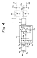
- Figs. 3 and 4 show another embodiment of this invention wherein two piezoelectric elements 4a and 4b connected in parallel to each other instead of the single piezoelectric element 4 shown in Figs. 1 and 2, and a metallic rigid member 30 and a capacitor C2 are added to the first embodiment shown in Figs. 1 and 2.
- electrodes 3a and 3b are provided on the upper surface of the element 4a and the lower surface of the element 4b, while an electrode 3b is provided between the lower surface of the element 4a and the upper surface of the element 4b.
- the capacitor C2 is connected between the output and input terminals of the operational amplifier 20.
- the metallic rigid member 30 are fixed to the insulation plate 9 together with the elements 4a and 4b and weight 2 by the metallic fixing screw 5 and nut 15.
- the electrodes 3a and 3b attached to the elements 4a and 4b are connected to the input terminals of the charged amplifier 6 by way of the feed lines 13 and 14 respectively.
- the two symmetric external electrodes 3a and 3b of the elements 4a and 4b are coupled by a line not shown.
- the values of the capacitor C2 and the resistor R5 are set so that the time constant thereof corresponds to, for example, 5 Hz.
- the second embodiment since there are an air layer inside the casing 1 and the elements 4a and 4b are fixed at the insulation plate 9 so as to be thermally insulated from the casing, any influence on the elements 4a and 4b from the change in the temperature outside the casing 1 is mitigated.
- This feature is the same as that in the first embodiment.
- the elements 4a and 4b retain heat due to the metallic weight 2, rigid member 30 and fastening screw 5 and nut 15, the temperature of the elements may be balanced and the gradient of the temperature change thereof may be more gentle.
- the elements 4a and 4b are located in symmetry as well as being connected in parallel, the pyroelectricity characteristics are thus off-set.
- the affect of the pyroelectricity caused by the change in temperature may be mitigated and such pyroelectricity may be off-set by the plurality of piezoelectric elements.
- this embodiment is stable against fluctuation in the source voltage, resistant to temperature drifting and will not amplify any unnecessary noise caused by vibration, the acceleration sensor being most appropriate for an automobile.
- Fig. 5 illustrates an improvement in the method of fixing the element 4 and weight 2 shown in Fig. 1 in which detection in a vertical direction of acceleration may be stable while unnecessary detection sensitivity in a lateral direction may be reduced.
- the acceleration sensor is only intended to detect acceleration in a vertical direction. It is to be noted, however, that the piezoelectric element will be subjected to a force caused by a rolling movement due to acceleration in a lateral direction, and as a consequence, the piezoelectric element may generate an output as a result of the rolling movement.
- a plate 30′ for reinforcing the fixing portion is used.
- the plate 30′ is made of a rigid material such as metal, and formed into an U shape.
- the insulation plate 9 is inserted in the U shape plate 30′ and the piezoelectric element 4 and weight 2 are placed on and fixed to the plate 30′ incorporating the insulation plate 9 by the fastening screw 5 and nut (not shown in Fig. 5), whereby any rolling movement may be reduced.
- this plate 30′ is fixed to the conductive casing 1 by way of the insulation plate 9, it can maintain its insulating function with regard to the casing 1 while it is mechanically fixed to the casing in a reliable fashion by means of screws or the like not shown, whereby the acceleration detection capability in a mechanical sense may be realized as in the prior arts.
- Fig. 6 shows an improved method of fixing the elements 4a and 4b and weight 2 shown in Fig. 3 in a similar manner to that shown in Fig. 5.
- the metallic rigid plate 30′ formed into an "U" shape is used instead of the plate, or member 30 shown in Fig. 3 and the insulation plate 9 is inserted in the U shape plate 30′.
- the piezoelectric elements 4a and 4b and the weight 2 are fixed to the insulation plate 9, together with the plate 30′, whereby any rolling movement may be reduced.
- thermal balancing between the elements 4a and 4b may be further optimized.
- the acceleration sensor has been described as having the grounding line 32 connected between the conductive casing 1 and the earth portion of the control unit 11, or the negative pole of the battery 12, in consideration of applications requiring high accuracy.
- the grounding line 32 When an insulated conductive casing 1 is attached to a body of an automobile or the like, one point grounding may be attained at the electronic control unit 11, and therefor no current due to common impedance will flow through the grounding line 32.
- an acceleration measurement preventing from the fluctuation in the source voltage may be made possible.
- the conductive casing 1 may be grounded to the body of the automobile without the grounding line 32 between the casing 1 and the negative pole of the battery 12.
- the weight 2 and piezoelectric element(s) 4 (4a, 4b) are fixed to the insulation plate which is a printed circuit board mounting the detection circuits, or the charged amplifier 6 and amplifier 7, they may be secured by separate insulation members to attain a similar effect.
- the capacitor C1 for converting the change of the charge at the piezoelectric element(s) to the corresponding voltage change may be selected such that it has a positive capacitive temperature coefficient, whereby a temperature characteristic of the detection may be compensated for.
- the charged amplifier 6 and metallic rigid plates 30 and 30′ should not be taken as being limited to those described above, and other constitutions may be employed.
Landscapes
- Physics & Mathematics (AREA)
- General Physics & Mathematics (AREA)
- Measurement Of Mechanical Vibrations Or Ultrasonic Waves (AREA)
- Force Measurement Appropriate To Specific Purposes (AREA)
- Measuring Fluid Pressure (AREA)
Applications Claiming Priority (4)
| Application Number | Priority Date | Filing Date | Title |
|---|---|---|---|
| JP327129/88 | 1988-12-23 | ||
| JP167296/88U | 1988-12-23 | ||
| JP63327129A JPH02171659A (ja) | 1988-12-23 | 1988-12-23 | 加速度センサ |
| JP1988167296U JPH0639337Y2 (ja) | 1988-12-23 | 1988-12-23 | 加速度センサ |
Publications (3)
| Publication Number | Publication Date |
|---|---|
| EP0374870A2 true EP0374870A2 (fr) | 1990-06-27 |
| EP0374870A3 EP0374870A3 (en) | 1990-08-22 |
| EP0374870B1 EP0374870B1 (fr) | 1993-04-07 |
Family
ID=26491385
Family Applications (1)
| Application Number | Title | Priority Date | Filing Date |
|---|---|---|---|
| EP89123528A Expired - Lifetime EP0374870B1 (fr) | 1988-12-23 | 1989-12-20 | Capteur d'accélération |
Country Status (4)
| Country | Link |
|---|---|
| US (1) | US5095751A (fr) |
| EP (1) | EP0374870B1 (fr) |
| AU (1) | AU599540B1 (fr) |
| DE (1) | DE68905913T2 (fr) |
Cited By (6)
| Publication number | Priority date | Publication date | Assignee | Title |
|---|---|---|---|---|
| EP0534366A1 (fr) * | 1991-09-24 | 1993-03-31 | Murata Manufacturing Co., Ltd. | Capteur d'accélération |
| GB2231965B (en) * | 1989-05-24 | 1994-02-16 | Mitsubishi Electric Corp | Piezoelectric accelerometer for automobiles |
| EP0622634A1 (fr) * | 1993-04-28 | 1994-11-02 | MAGNETI MARELLI S.p.A. | Dispositif de détection de cognage dans un moteur à combustion interne |
| GB2282450A (en) * | 1993-09-29 | 1995-04-05 | Roke Manor Research | Improvements in or relating to accelerometers |
| EP1037053A1 (fr) * | 1999-03-17 | 2000-09-20 | Murata Manufacturing Co., Ltd. | Amplificateur pour un accéléromètre piézoélectrique |
| KR20030008832A (ko) * | 2001-07-20 | 2003-01-29 | 에스브이 주식회사 | 가속도센서용 정전형 전하증폭기 |
Families Citing this family (11)
| Publication number | Priority date | Publication date | Assignee | Title |
|---|---|---|---|---|
| US5351542A (en) * | 1992-01-27 | 1994-10-04 | Kansei Corporation | Acceleration sensor assembly |
| DE4341662C2 (de) * | 1992-12-08 | 1997-01-23 | Murata Manufacturing Co | Beschleunigungssensor |
| DE69405962T2 (de) * | 1993-11-09 | 1998-04-09 | Murata Manufacturing Co | Beschleunigungsmessaufnehmer |
| RU2196997C1 (ru) * | 2002-04-10 | 2003-01-20 | ОАО Калужский завод "Автоприбор" | Пьезоэлектрический акселерометр |
| JP2004077255A (ja) * | 2002-08-15 | 2004-03-11 | Fujitsu Media Device Kk | 加速度センサ |
| DE102004003200B4 (de) * | 2004-01-22 | 2020-03-26 | Robert Bosch Gmbh | Vorrichtung zur Überwachung von jeweiligen Andruckkräften zwischen wenigstens einem Steuergerät und einer Fahrzeugkarosserie |
| DE102005006666A1 (de) * | 2005-02-14 | 2006-08-24 | Fraunhofer-Gesellschaft zur Förderung der angewandten Forschung e.V. | Piezoelektrischer Sensor und dessen Verwendung |
| KR20090068202A (ko) * | 2006-10-02 | 2009-06-25 | 싸이버옵틱스 쎄미콘덕터 인코퍼레이티드 | 중복 가속도계를 갖는 가속 센서 |
| US7778793B2 (en) * | 2007-03-12 | 2010-08-17 | Cyberoptics Semiconductor, Inc. | Wireless sensor for semiconductor processing systems |
| US8833165B2 (en) * | 2009-02-17 | 2014-09-16 | Agency For Science, Technology And Research | Miniaturized piezoelectric accelerometers |
| WO2025170994A1 (fr) * | 2024-02-09 | 2025-08-14 | Industrial Consulting Automation Research Engineering SRL | Procédé et appareil de production automatisée d'accéléromètres piézoélectriques |
Family Cites Families (11)
| Publication number | Priority date | Publication date | Assignee | Title |
|---|---|---|---|---|
| GB1258176A (fr) * | 1968-12-09 | 1971-12-22 | ||
| GB1277768A (en) * | 1969-11-18 | 1972-06-14 | Vibro Meter A G | Improvements in or relating to signal transmitting circuit arrangements |
| US4085349A (en) * | 1976-03-12 | 1978-04-18 | Ird Mechanalysis, Inc. | Piezo electric transducer for measuring instantaneous vibration velocity |
| JPS57126026U (fr) * | 1981-01-30 | 1982-08-06 | ||
| US4417476A (en) * | 1982-04-01 | 1983-11-29 | General Electric Company | Charge converter for vibration monitoring instrumentation |
| DE3371417D1 (en) * | 1983-02-21 | 1987-06-11 | Vibro Meter Ag | Dual accelerometer, method of manufacturing it and its application |
| US4620442A (en) * | 1984-06-14 | 1986-11-04 | Sundstrand Data Control, Inc. | Digital accelerometer |
| FR2600424B1 (fr) * | 1986-06-23 | 1989-02-17 | Inst Francais Du Petrole | Procede et dispositif pour ameliorer la sensibilite et le rapport du signal au bruit de transducteurs piezo-electriques comportant une pluralite de capteurs combines en parallele |
| DE3870246D1 (de) * | 1987-06-18 | 1992-05-21 | Kellett Michael A | Akzelerometer und zugehoerige steuerschaltungen. |
| US4816713A (en) * | 1987-10-09 | 1989-03-28 | Change Jr Nicholas D | Piezoelectric sensor with FET amplified output |
| GB8728509D0 (en) * | 1987-12-05 | 1988-01-13 | Rolls Royce Plc | Acoustic emission transducer |
-
1989
- 1989-12-20 EP EP89123528A patent/EP0374870B1/fr not_active Expired - Lifetime
- 1989-12-20 DE DE89123528T patent/DE68905913T2/de not_active Expired - Fee Related
- 1989-12-22 AU AU47295/89A patent/AU599540B1/en not_active Ceased
- 1989-12-22 US US07/455,015 patent/US5095751A/en not_active Expired - Lifetime
Cited By (10)
| Publication number | Priority date | Publication date | Assignee | Title |
|---|---|---|---|---|
| GB2231965B (en) * | 1989-05-24 | 1994-02-16 | Mitsubishi Electric Corp | Piezoelectric accelerometer for automobiles |
| EP0534366A1 (fr) * | 1991-09-24 | 1993-03-31 | Murata Manufacturing Co., Ltd. | Capteur d'accélération |
| EP0646799A3 (fr) * | 1991-09-24 | 1998-12-16 | Murata Manufacturing Co., Ltd. | Capteur d'accélération |
| EP0646798A3 (fr) * | 1991-09-24 | 1998-12-16 | Murata Manufacturing Co., Ltd. | Capteur d'accélération |
| EP0622634A1 (fr) * | 1993-04-28 | 1994-11-02 | MAGNETI MARELLI S.p.A. | Dispositif de détection de cognage dans un moteur à combustion interne |
| GB2282450A (en) * | 1993-09-29 | 1995-04-05 | Roke Manor Research | Improvements in or relating to accelerometers |
| GB2282450B (en) * | 1993-09-29 | 1997-03-26 | Roke Manor Research | Improvements in or relating to accelerometers |
| EP1037053A1 (fr) * | 1999-03-17 | 2000-09-20 | Murata Manufacturing Co., Ltd. | Amplificateur pour un accéléromètre piézoélectrique |
| US6246287B1 (en) | 1999-03-17 | 2001-06-12 | Murata Manufacturing Co., Ltd. | Amplifier for piezoelectric acceleration sensor |
| KR20030008832A (ko) * | 2001-07-20 | 2003-01-29 | 에스브이 주식회사 | 가속도센서용 정전형 전하증폭기 |
Also Published As
| Publication number | Publication date |
|---|---|
| AU599540B1 (en) | 1990-07-19 |
| EP0374870A3 (en) | 1990-08-22 |
| DE68905913T2 (de) | 1993-09-30 |
| DE68905913D1 (de) | 1993-05-13 |
| EP0374870B1 (fr) | 1993-04-07 |
| US5095751A (en) | 1992-03-17 |
Similar Documents
| Publication | Publication Date | Title |
|---|---|---|
| US5095751A (en) | Acceleration sensor | |
| US5063782A (en) | Accelerometers and associated control circuits | |
| US5088326A (en) | Piezoelectric accelerometer for automobiles | |
| US5130600A (en) | Acceleration sensor | |
| US5600066A (en) | Capacitive accelerometer with a circuit for correcting stray capacitance perturbations | |
| US5347867A (en) | Accelerometer incorporating a driven shield | |
| US5304941A (en) | Sensor detection signal extracting circuit with offset voltage cancelling ability | |
| US6311406B1 (en) | Electrostatic capacitor-type inclination sensor | |
| EP0172301B1 (fr) | Dispositif détecteur des modifications de l'inclinaison d'un corps | |
| KR920009803B1 (ko) | 가속도 감지기 | |
| JP2607858Y2 (ja) | 静電容量形音響トランスデューサを試験するためのシステム | |
| JPH0639337Y2 (ja) | 加速度センサ | |
| JPH0640016B2 (ja) | 電磁式負荷補償秤の容量性の位置検出器 | |
| JP3006652B2 (ja) | 車両用角速度センサの車体取付構造 | |
| JPH0615997B2 (ja) | 温度圧力検出装置 | |
| JPH0943270A (ja) | 圧電型力学量センサ | |
| JPH0355918Y2 (fr) | ||
| JPH06265573A (ja) | 加速度センサ | |
| JP2734836B2 (ja) | 力学量検出器 | |
| JPS63173970A (ja) | 加速度センサ | |
| JPH044230Y2 (fr) | ||
| JPS63195573A (ja) | 圧電型加速度センサ− | |
| JP3157907B2 (ja) | 加速度検出装置 | |
| RU71773U1 (ru) | Малогабаритный высокочувствительный датчик ускорений | |
| JP2004212212A (ja) | インピーダンス検出装置及びインピーダンス検出方法 |
Legal Events
| Date | Code | Title | Description |
|---|---|---|---|
| PUAI | Public reference made under article 153(3) epc to a published international application that has entered the european phase |
Free format text: ORIGINAL CODE: 0009012 |
|
| AK | Designated contracting states |
Kind code of ref document: A2 Designated state(s): DE FR GB |
|
| PUAL | Search report despatched |
Free format text: ORIGINAL CODE: 0009013 |
|
| AK | Designated contracting states |
Kind code of ref document: A3 Designated state(s): DE FR GB |
|
| 17P | Request for examination filed |
Effective date: 19901231 |
|
| 17Q | First examination report despatched |
Effective date: 19911210 |
|
| GRAA | (expected) grant |
Free format text: ORIGINAL CODE: 0009210 |
|
| RIN1 | Information on inventor provided before grant (corrected) |
Inventor name: YANO, MASAYUKI HIMEJI JIGYOSHO OF MITSUBISHI Inventor name: WADA, SHUNICHI C/O HIMEJI SEISKUSHO |
|
| AK | Designated contracting states |
Kind code of ref document: B1 Designated state(s): DE FR GB |
|
| REF | Corresponds to: |
Ref document number: 68905913 Country of ref document: DE Date of ref document: 19930513 |
|
| ET | Fr: translation filed | ||
| PLBE | No opposition filed within time limit |
Free format text: ORIGINAL CODE: 0009261 |
|
| STAA | Information on the status of an ep patent application or granted ep patent |
Free format text: STATUS: NO OPPOSITION FILED WITHIN TIME LIMIT |
|
| 26N | No opposition filed | ||
| PGFP | Annual fee paid to national office [announced via postgrant information from national office to epo] |
Ref country code: FR Payment date: 20011212 Year of fee payment: 13 |
|
| PGFP | Annual fee paid to national office [announced via postgrant information from national office to epo] |
Ref country code: GB Payment date: 20011219 Year of fee payment: 13 |
|
| REG | Reference to a national code |
Ref country code: GB Ref legal event code: IF02 |
|
| PGFP | Annual fee paid to national office [announced via postgrant information from national office to epo] |
Ref country code: DE Payment date: 20020109 Year of fee payment: 13 |
|
| PG25 | Lapsed in a contracting state [announced via postgrant information from national office to epo] |
Ref country code: GB Free format text: LAPSE BECAUSE OF NON-PAYMENT OF DUE FEES Effective date: 20021220 |
|
| PG25 | Lapsed in a contracting state [announced via postgrant information from national office to epo] |
Ref country code: DE Free format text: LAPSE BECAUSE OF NON-PAYMENT OF DUE FEES Effective date: 20030701 |
|
| GBPC | Gb: european patent ceased through non-payment of renewal fee |
Effective date: 20021220 |
|
| PG25 | Lapsed in a contracting state [announced via postgrant information from national office to epo] |
Ref country code: FR Free format text: LAPSE BECAUSE OF NON-PAYMENT OF DUE FEES Effective date: 20030901 |
|
| REG | Reference to a national code |
Ref country code: FR Ref legal event code: ST |